1
GRUNDFOS INSTRUCTIONS
Redi-Flo Variable
Frequency Drive
USA Installation and operating instructions
SAFETY NOTICE
This equipment contains voltages that may be as great as 1000 volts! Electrical shock
can cause serious or fatal injury. Only qualified personnel should attempt the start–up
procedure or troubleshoot this equipment.
PRECAUTIONS:
1
WARNING:
Do not touch any circuit board, power device or electrical
connection before you first ensure that power has been
disconnected and there is no high voltage present from this
equipment or other equipment to which it is connected. Electrical
shock can cause serious or fatal injury. Only qualified personnel
should attempt the start–up procedure or troubleshoot this equipment.
WARNING:
Be sure the system is properly grounded before applying power.
Do not apply AC power before you ensure that grounds are
connected. Electrical shock can cause serious or fatal injury.
WARNING:
Do not remove cover for at least five (5) minutes after AC power is
disconnected to allow capacitors to discharge. Electrical shock can
cause serious or fatal injury.
CAUTION:
Disconnect motor leads (T1, T2 and T3) from control before you
perform a “Megger” test on the motor. Failure to disconnect motor
from the control will result in extensive damage to the control. The
control is tested at the factory for high voltage / leakage resistance
as part of Underwriter Laboratory requirements.
CAUTION:
Do not connect AC power to the Motor terminals T1, T2 and T3.
Connecting AC power to these terminals may result in damage to
the control.
1
QUICK START GUIDE
QUICK START GUIDE
To operate the Redi-Flo VFD system, simply:
1. Submerge the RF2 or RF4 pump in the water to be pumped.
2. Connect the motor lead to the Redi-Flo VFD. (Note: With RF4 Variable Performance
Pumps you must have an adapter cord to connect to Redi-Flo VFD.
#3 and #4 for operation with generator only.
WARNING: Do not let the generator run out of gas while powering the VFD.
If it surges and creates excessive voltage, internal VFD damage could result.
3. If using a generator, start the generator and allow it to warm up.
4. If the generator has a circuit breaker, close the breaker and check the output
voltage from the generator. The output voltage must be within the specified
ranges (refer to Technical Specifications, at the end of this manual) to ensure proper
operation and prevent damage to the system. If the voltage is too high or too low,
adjustments to the generator must be performed to allow the system to run.
5. Plug the Redi-Flo VFD into a generator or connect to utility power supply. The unit
accepts 115V or 230V sources. Refer to the Input Power Terminals section for wiring instructions.
WARNING: Incorrect wiring on the 115V or 230V terminals will damage the drive.
6. The VFD will initialize and be ready to drive the motor. After the initialization screen
appears, the following will be displayed:
• STP means the drive is stopped
• V indicates motor volts
STP
0V
REDIFL2
• REDIFL2 indicates Redi-Flo2 pump mode
• LOC means the drive is in Local Keypad Mode
LOC
0.0A
0.00HZ
• A indicates motor amps
• HZ indicates motor frequency
The VFD defaults to Redi-Flo2 operation. To change to Redi-Flo4 press the sequence SHIFT-▼-SHIFT keys.
Use sequence SHIFT-▲-SHIFT to return to Redi-Flo2.
7. Press the FWD key to start the motor and use the ▲ and ▼ arrow keys to increase
or decrease speed. Continuous holding of the arrow key will increase the rate of speed
change. The STOP key is used to stop the motor.
8. Pressing the ENTER key allows the user to quickly set the speed to any given value
by using the ▲ and ▼ arrows to change speed and the SHIFT key to cursor between digits.
9. When powering down, unplug the Redi-Flo VFD from the generator BEFORE
removing the motor lead from the Redi-Flo VFD or turning off the generator.
Note: To prevent tripping power source circuit breakers please observe the following: When using the Redi-FFlo4
pump and a VFD power source of 115VAC, motor speeds of greater than 70Hz may draw over 15 amps. For
230VAC power source motor speeds greater than 90 Hz may draw over 15 amps. In RediFlo4 mode, 100 Hz
cannot be exceeded without changing parameters.
1
2
PRE-INSTALLATION CHECKLIST
Components of Your Redi-FFlo VFD System
Your Redi-Flo Variable Performance Pump system should contain the following
components:
1. Redi-Flo Variable Frequency Drive, (See Figure 1)
2. Either a Redi-Flo2® pump and motor with lead (Figure 2) or a Redi-Flo4™ Variable
Performance pump, motor, lead, lead/plug and RF4 x VFD adapter cord (Figure 3).
Figure 2
Figure 1
Redi-Flo2®
Figure 3
Redi-Flo4®
To operate the system you will also need:
1. A discharge hose or pipe to connect to the pump (See Figure 4).
2. An electrical plug to connect the Redi-Flo VFD power cord to your portable
generator may be needed if the supplied plug is not compatible with your generator (See Figure 5).
3. Safety cable and hardware for lowering and lifting the pump (See Figure 6).
Figure 4
Figure 5
Figure 6
The exact type of plug used will depend
upon your generator, The Redi-Flo VFD
is supplied with a standard NEMA 5-15P,
115V, 3 prong plug.
Redi-Flo2®
3
Redi-Flo4®
1
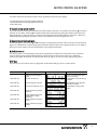
ASSEMBLING THE REDI-FLO VFD SYSTEM
INPUT POWER TERMINALS
The input voltage can be changed between 115V and 230V by changing the line input
connections as shown below:
Warning - If the Redi-FFlo VFD is miswired for the incoming voltage, internal damage
may occur to the drive.
230VAC
115VAC
-----230VAC-----
R2
Bt/R1
B-
T1
-----------115VAC----------Hot
Neutral
T2
T3
GND
Green
Attaching the Pump to the pipe
When connecting the discharge pipe or tubing to the pump, a back-up wrench should be used. It is
recommended that a safety cable be attached to the pump (using special brackets and cables, sold separately)
anytime plastic pipe or flexible tubing is used (as shown if figure 6). A check valve may also be added to
Redi-Flo2® pumps to prevent fluid from flowing back into the pump after it is turned off (backflow prevention).
A check valve is standard on Redi-Flo4™ pumps. Always check to ensure joints are fastened securely. The use of
a torque arrestor is not required when using the Redi-Flo VFD.
Lowering the Pump Into the Well
Make sure the electrical motor leads are not cut or damaged in any way when the pump is being lowered into the
well. Do not use the motor leads to support the weight of the pump. To protect against surface water entering the
well and contaminating the well, the well should be finished off utilizing a locally approved well seal.
The motor lead should be secured to the discharge pipe or tubing at frequent intervals to prevent sagging,
looping and possible motor lead damage. Teflon® wire ties are recommended for environmental applications.
IMPORTANT
Plastic pipe and tubing tend to stretch under load. This stretching must be taken into account when securing the motor lead
to the riser pipe or tubing. Leave three to four inches of slack between clipped points. This tendency to stretch will also affect
the calculation of the pump setting depth. When plastic pipe or tubing is used, it is recommended that a safety cable be
attached to the pump to raise and lower it. Redi-Flo4™ pumps are designed to accommodate this cable and Redi-Flo2®
pumps can be fitted with a safety cable bracket (part number 1A0019).
1
4
ASSEMBLING THE REDI-FLO VFD SYSTEM
OPERATING CONDITIONS
To ensure the Redi-Flo Variable Performance Pumping system operates properly, follow these guidelines:
• The Redi-Flo2® or Redi-Flo4™ pump must be installed vertically with the discharge end pointed upwards.
• The electrical voltage supply to the Redi-Flo VFD must always be within + or - 10% of the specified power
supply ( 103.5 - 126.5 VAC at 115V connection or 207 - 253 VAC at 230V ).
• For best performance when operating on a generator, 115V generators should be set at 120V without load and
230V generators should be set at 240V without load. Use a separate meter to set voltage; do not rely on builtin meters found on generators. Verify generator voltage stays within tolerance at full load.
• The pump and motor must always be completely submerged in fluid to ensure
lubrication and cooling of the motor.
• The temperature of the fluid being pumped should be according to the technical
specifications shown in the motor specifications.
• The installation depth of the pump should always be at least three feet below the maximum drawdown level
of the well.
• Redi-Flo pumps are not recommended for well development or pumping fluid
containing abrasives.
• Redi-Flo2® pumps are not recommended for continuous operation applications.
• The warranty of the Redi-Flo pumps will be void if other than the Redi-Flo VFD is used or if corrosive fluids are
pumped.
• The service life of dedicated Redi-Flo pumps may be compromised if the ambient water quality exceeds one or
more of the following values:
pH<5
DO>2 ppm
H2S>1 ppm
CL->500 ppm
TDS>1000 ppm
Adherence To Environmental Regulations
When handling and operating the Redi-Flo Variable Performance Pump system, all environmental regulations
concerning the handling of hazardous materials must be observed. When the pump is taken out of operation,
great care should be taken to ensure that the pump contains no hazardous materials that might cause injury to
human health or to the environment.
Purging A Well
If the pump is used to purge a well, start the pump at minimum speed and gradually increase to desired speed.
Redi-Flo products are not recommended for well development.
Generator Usage
Minimum generator size
For generators with voltage regulation
For generators without voltage regulation
Recommended for optimal performance
5
(Redi-FFlo2/Redi-FFlo4)
2500/3400 watts at 115/230VAC, single phase
5000/6700 watts at 115/230VAC, single phase
4000/5400 watts at 115/230 VAC, single phase
with voltage regulation
1
REDI-FLO VFD SPECIAL FEATURES
Dual Input Capability
Redi-Flo VFD can accept 115V or 230V single phase input voltage. Refer to the input power
terminal section on page 4 for connection instructions.
Enclosure
The Redi-Flo VFD NEMA 4 enclosure is designed for outdoor duty and is resistant to
damage as a result of incidental exposure to rain.
UL Approvals
The Redi-Flo VFD is UL Listed to U.S. and Canadian electrical safety standards.
Dual Functionality
The Redi-Flo VFD can change from operating Redi-Flo2® (MP1) to Redi-Flo4™
Variable Performance pumps with a few keystrokes.
Optimized Volts/Frequency (V/HZ) Pattern
The Redi-Flo VFD V/Hz pattern is specially optimized to allow the most efficient
operation of Redi-Flo2® and Redi-Flo4™ variable performance pumps.
1
6
REDI-FLO VFD KEYPAD OVERVIEW
Overview
The keypad is used to program the control parameters, to operate the motor and to monitor the status
and outputs of the control by accessing the display options, diagnostic menus and the fault log.
Indicator Lights
JOG - (Green) lights when Jog is active.
FWD - (Green) lights when FWD direction is commanded.
REV - (Green) lights when REV direction is commanded.
STOP - (Red) lights when motor STOP is commanded.
Keypad Display - Displays status
information during Local or Remote
operation. It also displays information
during parameter setup and fault or
Diagnostic Information.
Motor Selection - The VFD defaults to
Redi-Flo2 operation, to change to
Redi-Flo 4, press the key sequence
“Shift -▼- Shift.” Use the sequence
“Shift -▲- Shift” to return to Redi-Flo2.
JOG - Press JOG to select the
preprogrammed jog speed. After the
jog key has been pressed, use the FWD
or REV keys to run the motor in the
direction that is needed. The JOG key is
only active in the local mode.
FWD - Press FWD to initiate forward
rotation of the motor. (Active in Local
and Jog modes).
REV - Press REV to initiate reverse
rotation of the motor. (Active in Local
and Jog modes).
STOP - Press STOP to initiate a stop
sequence. Depending on the setup of
the control, the motor will either regen
or coast to a stop. This key is
operational in all modes of operation
unless it has been disabled by the
Keypad Stop parameter in the Keypad
(programming) Setup Block.
LOCAL - Press LOCAL to change
between the local (keypad) and remote
operation.
7
PROG - Press PROG to enter the
program mode. While in the program
mode the PROG key is used to edit a
parameter setting.
DISP - Press DISP to return to display
mode from programming mode.
Provides operational status and
advances to the next display menu
item.
SHIFT - Press SHIFT in the program
mode to control cursor movement.
Pressing the SHIFT key once moves the
blinking cursor one character position
to the right. While in program mode, a
parameter value may be reset to the
factory preset value by pressing the
SHIFT key until the arrow symbols at
the far left of the keypad display are
flashing, then press an arrow key. In
the display mode the SHIFT key is used
to adjust the keypad contrast.
RESET - Press RESET to
clear all fault messages (in local mode).
Can also be used to return to the top of
the block programming menu without
saving any parameter value changes.
▲ (UP Arrow).
Press ▲ to change the value of the
parameter being displayed. Pressing ▲
increments the value to the next
greater value. Also, when the fault log
or parameter list is displayed, the ▲
key will scroll upward through the list.
In the local mode pressing the ▲ key
will increase motor speed to the next
greater value.
ENTER - Press ENTER to save parameter
value changes and move back to the
previous level in the programming
menu. In the display mode the ENTER
key is used to directly set the local
speed reference. It is also used to select
other operations when prompted by
the keypad display.
▼ (Down Arrow)
Press ▼ to change the value of the
parameter being displayed. Pressing ▼
decrements the value to the next lesser
value. Also, when the fault log or
parameter list is displayed, the ▼ key
will scroll downward through the list.
In the local mode pressing the ▼ key
will decrease motor speed to the next
lesser value.
1
MOTOR CONTROL VIA KEYPAD
The Redi-Flo VFD can operate the motor in three (3) different ways from the keypad.
1. Speed adjustment using the Keypad arrow keys
2. Speed adjustment with Keypad entered values
3. JOG Command
1) Keypad arrow speed control
Press FWD or REV to select desired direction of motor rotation, then press or hold the up arrow key ▲ to increase
speed or use the down arrow key ▼ to reduce motor speed. Continuously holding the arrow key will cause the
speed to change in larger increments. The minimum speed increment produced by the arrow keys is defined in
PROG/Keypad Setup/Keypad Speed INC. Default value of 0.10 Hz can be changed by the user.
2) Keypad speed entered value
Press the ENTER key and use the ▲ and ▼ arrow keys to adjust digits and the SHIFT key to cursor to the desired
digit. Press ENTER when finished selecting desired motor speed to return to the display mode. Press the FWD or
REV key to run the motor in the desired direction at the programmed speed.
3) JOG Command
The JOG key can be used to ramp the pump up to a predetermined speed in the forward or reverse direction.
Press the JOG key then hold the FWD or REV key, and the pump will ramp to the speed set in PROG/Jog
Settings/Jog Speed. Acceleration and deceleration times for Jog can also be set in this programming menu.
DISP Key
The DISP key can be used for accessing diagnostic and troubleshooting screens as shown below:
Action
Apply Power
Display
Comments
Press DISP key
Press DISP key
Scroll to diagnostic info block.
Press ENTER to view diagnostic
information if desired.
Press DISP key
Scroll to local speed ref. block.
Press ENTER to change motor
speed.
Press DISP key
Display mode showing output
frequency.
Press DISP key
Display mode showing motor
speed (based on output
frequency).
Display mode showing output
current.
Press DISP key
Press DISP key
1
Description
Display mode showing mode,
voltage, current & frequency
status.
Scroll to fault log block.
redifl2
No faults present. Local keypad
mode. If in remote mode, press
local for this display.
Press ENTER to view the fault log
if desired.
Display mode showing output
voltage.
8
MOTOR CONTROL VIA KEYPAD
Adjusting Display Contrast
When AC power is applied to the VFD, the keypad should display the status of the
unit. If there is no display visible, or if it is difficult to read, use the following procedure to adjust the display.
Contrast may be adjusted in the display mode when motor is stopped or running.
Action
Description
Apply Power
No visible display
Press DISP Key
Places control in display mode
Display
Comments
Display mode.
Press SHIFT key 2 times Allows display contrast
adjustment
9
Press Y or B Key
Adjusts display intensity
Press ENTER
Saves level of contrast and exits
to display mode
1
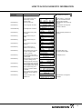
PROG MENU
Advanced Programming
A password is required for advanced programming features. Altering some default settings for Redi-FFlo2 or
Redi-FFlo4 could possibly damage the motor or VFD. For additional programming instructions, please refer to
the full programming guide found at the Baldor website: www.Baldor.com The manual can be found under
Support — installation and operation manuals. It is Baldor manual number MN715, Series 15H Inverter.
LEVEL 1 BLOCKS
Preset Speeds
Preset Speed #1
Preset Speed #2
Preset Speed #3
Preset Speed #4
Preset Speed #5
Preset Speed #6
Preset Speed #7
Preset Speed #8
Preset Speed #9
Preset Speed #10
Preset Speed #11
Preset Speed #12
Preset Speed #13
Preset Speed #14
Preset Speed #15
Accel / Decel Rate
Accel Time #1
Decel Time #1
S-Curve #1
Accel Time #2
Decel Time #2
S-Curve #2
Jog Settings
Jog Speed
Jog Accel Time
Jog Decel Time
Jog S-Curve
Keypad Setup
Keypad Stop Key
Keypad Stop Mode
Keypad Run Fwd
Keypad Run Rev
Keypad Jog Fwd
Keypad Jog Rev
3 Speed Ramp
Switch on Fly
LOC. Hot Start
LEVEL 2 BLOCKS
Input
Operating Mode
Command Select
ANA CMD Inverse
ANA CMD Offset
ANA CMD Gain
CMD SEL Filter
Power Up Mode
Output Limits
Operating Zone
Min Output Frequency
Max Output Frequency
PK Current Limit
REGEN Limit
REGEN Limit ADJ
PWM Frequency
Output
Digital Out #1
Digital Out #2
Digital Out #3
Digital Out #4
Zero SPD Set PT
At Speed Band
Set Speed Point
Analog Out #1
Analog Out #2
Analog Scale #1
Analog Scale #2
Underload Set Point
Custom Units
MAX Decimal Places
Value at Speed
Value DEC Places
Value Speed REF
Units of Measure
Units of MEAS 2
V/HZ and Boost
Ctrl Base Frequency
Torque Boost
Dynamic Boost
Slip Comp Adj
V/HZ Profile
V/HZ 3-PT Volts
V/HZ 3-PT Frequency
Max Output Volts
Protection
External Trip
Local Enable INP
Miscellaneous
Restart Auto/Man
Restart Fault/Hr
Restart Delay
Factory Settings
Language Select
STABIL ADJ Limit
Stability Gain
Security Control
Security State
Access Timeout
Access Code
Motor Data
Motor Voltage
Motor Rated Amps
Motor Rated Speed
Motor Rated Frequency
Motor Mag Amps
Brake Adjust
Resistor Ohms
Resistor Watts
DC Brake Voltage
DC Brake Frequency
Brake on Stop
Brake on Reverse
Stop Brake Time
Brake on Start
Start Brake Time
Process Control
Process Feedback
Process Inverse
Setpoint Source
Setpoint Command
Set PT ADJ Limit
At Setpoint Band
Process PROP Gain
Process INT Gain
Process DIFF Gain
Follow I:O Ratio
Follow I:O Out
Encoder Lines
Integrator Clamp
Minimum Speed
Skip Frequency
Skip Frequency #1
Skip Band #1
Skip Frequency #2
Skip Band #2
Skip Frequency #3
Skip Band #3
Synchro Starts
Synchro Starts
Sync Start Frequency
Sync Scan V/F
Sync Setup Time
Sync Scan Time
Sync V/F Recover
Sync Direction
Communications
Protocol
Baud Rate
Drive Address
1
10
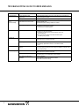
TROUBLESHOOTING GUIDE TO ERROR MESSAGES
INDICATION
Command Select
POSSIBLE CAUSE
CORRECTIVE ACTION
Incorrect operating mode
programmed.
Change Operating Mode in the Level 1 Input block to one that does not
require the expansion board.
Need expansion board.
Install the correct expansion board for selected operating mode.
DECEL Rate set too low a value
Lengthen DECEL time.
Add external dynamic braking resistors or module.
Input voltage too high.
Verify proper AC line voltage.
Use step down transformer if needed.
Use line reactor to minimize spikes.
Bus Undervoltage
Input voltage too low.
Verify proper AC line voltage.
Use step up transformer if needed.
Check power line disturbances (sags caused by start up of
other equipment).
Monitor power line fluctuations with date and time imprint
to isolate power problem.
External Trip
Motor draws excessive current.
Check motor for overloading.
Verify proper sizing of control and motor.
External trip parameter incorrect.
Verify connection of external trip circuit at J4-16.
Bus Overvoltage
Trip or
HW Overvoltage
Set external trip parameter to “OFF” if no connection made
at J4-16.
11
Hardware Protect
Fault duration too short to be
identified.
Reset control.
Check for proper grounding of power wiring and shielding of signal wiring.
Replace control board.
Heatsink Temp
Motor Overloaded.
Correct motor loading.
Verify proper sizing of control and motor.
Ambient temperature too high.
Relocate control to cooler operating area.
Add cooling fans or air conditioner to control cabinet.
Built-in fans are ineffective or
inoperative.
Verify fan operation.
Remove debris from fan and heatsink surfaces.
Replace fan or check fan wiring.
1
TROUBLE SHOOTING GUIDE (CONT.)
INDICATION
CORRECTIVE ACTION
HW Desaturation
Accel/Decel rate set too short.
Torque Boost set too high.
Electrical noise in logic circuits.
Motor overloaded.
Lengthen Accel/Decel rate.
Reduce torque boost value.
Check for proper grounding of power wiring and shielding of signal wiring.
Verify proper sizing of control and motor or reduce motor load.
HW Power
Supply
Power supply malfunctioned.
Check internal connections.
Replace logic power board.
HW Ground Fault
Output current (motor current)
leakage to ground.
Disconnect wiring between control and motor. Retry test.
If GND FLT is cleared, reconnect motor leads and retry the test. Repair
motor if internally shorted.
Replace motor lead wire with low capacitance cable.
If GND FLT remains, contact your dealer.
Motor Will Not
Start
Motor overloaded.
Check for proper motor loading.
Check couplings for binding.
Verify proper sizing of control and motor.
Motor may be commanded to run
below minimum frequency setting.
Increase speed command or lower minimum frequency setting.
Incorrect Command Select
parameter.
Change Command Select parameter to match wiring at J4.
Incorrect frequency command.
Verify control is receiving proper command signal at J4.
Max Frequency Limit set too low.
Adjust Max Frequency Limit parameter value.
Motor overloaded.
Check for mechanical overload. If unloaded motor shaft does not rotate
freely, check motor bearings.
Improper speed command.
Verify control is receiving proper command signal at input terminals.
Verify control is set to proper operating mode to receive your speed
command.
MIN Output Speed parameter set
too high.
Adjust MIN Output Speed parameter value.
Improper speed command.
Verify control is receiving proper command signal at input terminals.
Verify control is set to receive your speed command.
Torque boost set too high.
Adjust torque boost parameter value.
Misalignment of coupling.
Check motor/load coupling alignment.
Faulty motor.
Replace with a new motor.
Motor Will Not
Reach Maximum
Speed
Motor Will Not
Stop Rotation
Motor runs rough
at low speed
1
POSSIBLE CAUSE
12
TROUBLE SHOOTING GUIDE (CONT.)
INDICATION
13
POSSIBLE CAUSE
CORRECTIVE ACTION
New Base ID
Replaced Control or circuit board.
Restore parameters to factory settings.
Reset control.
No Display
Lack of input voltage.
Check input power for proper voltage.
Loose connections.
Check input power termination.
Verify connection of operator keypad.
Adjust display contrast.
See Adjust Display Contrast.
NV Memory Fail
Memory fault occurred.
Press “RESET” key on keypad. Restore parameter values to factory
settings. If fault remains, call dealer.
3 Sec Overload
Peak output current exceeded 3 sec Check PK Current Limit parameter in the Level 2
rating.
Output Limits block.
Check motor for overloading.
Increase ACCEL time.
Reduce motor load.
Verify proper sizing of control and motor.
1 Min Overload
Peak output current exceeded 1
minute rating.
Check PK Current Limit parameter in the Level 2
Output Limits block.
Check motor for overloading.
Increase ACCEL/DECEL times.
Reduce motor load.
Verify proper sizing of control and motor.
Over Speed
Motor exceeded 110% of MAX
Output Freq parameter value.
Check Max Output Freq in the Level 2 Output Limits block.
Param Checksum
Memory fault occurred.
Press “RESET” key on keypad. Restore parameter values to factory
settings. If fault remains, call dealer.
Unknown Fault
Code
Microprocessor detected a fault that
is not defined in the fault code table.
Press “RESET” key on keypad. Restore parameter values to factory
settings. If fault remains, call dealer.
Unstable Speed
Oscillating load.
Unstable input power.
Slip compensation too high.
Correct motor load.
Correct input power.
Adjust slip compensation.
uP Reset
A software watchdog timer has
reset the processor because a
process has timed out.
Press “RESET” key on keypad. If fault remains, call dealer.
FLT Log MEM
Fail
Corrupt data in fault log (may occur
on older systems only).
Press “RESET” key on keypad. If fault remains, call dealer.
Current SENS
FLT
Failure to sense phase current.
Press “RESET” key on keypad. If fault remains, call dealer.
Bus Current
SENS
Failure to sense bus current.
Press “RESET” key on keypad. If fault remains, call dealer.
1
HOW TO ACCESS DIAGNOSTIC INFORMATION
Action
Description
Display
Comments
Apply Power
1
Logo display for 5 seconds.
Press DISP key
Display mode showing Local
mode voltage, current &
frequency status.
Scroll to fault log block.
Press DISP key
Scroll to diagnostic info block.
Press ENTER to view diagnostic
information if desired.
Press ENTER key
Access diagnostic information.
.
Press DISP key
Display mode showing control
temperature.
redifl2
25.0
No faults present. Local keypad
mode. If in remote/serial mode,
press local for this display.
Press ENTER to view the fault log
if desired.
Displays operating temperature in
degrees C.
Press DISP key
Display mode showing bus
voltage.
Press DISP key
Display mode showing bus
Current.
Press DISP key
Display mode showing PWM
Frequency.
Press DISP key
Display mode showing %
overload current remaining.
Press DISP key
Display mode showing real time
opto inputs & outputs states.
(0=Open, 1=Closed)
Opto Inputs states (Left);
Opto Outputs states (Right).
Press DISP key
Display mode showing actual
drive running time since the Fault
log was cleared.
HR.MIN.SEC format.
Press DISP key
Display operating zone with rated
hp and input voltage (for the
operating zone) and control type.
Press DISP key
Display mode showing continuous
amps; PK amps rating; amps/volt
scale of feedback, power base ID.
Press DISP key
Display mode showing which
Group1 or 2 expansion boards
are installed.
Press DISP key
Display mode showing software
version and revision installed in
the control.
Press DISP key
Displays exit choice. Press
ENTER to exit.
2497
Press ENTER to exit diagnostic
information.
14
HOW TO ACCESS THE FAULT LOG
When a fault condition occurs, motor operation stops and a fault code is displayed on the Keypad display.
The control keeps a log of the last 31 faults. If more than 31 faults have occurred, the oldest fault will be deleted
from the fault log. To access the fault log, perform the following procedure:
Action
Description
Display
Comments
Apply Power
Logo display for 5 seconds.
Display mode showing Local
mode voltage, current &
frequency status.
redifl2
No faults present. Local keypad
mode. If in remote/serial mode,
press local for this display.
Press DISP key
Press DISP to scroll to the Fault
Log entry point.
Press ENTER key
Display first fault type and time
fault occurred.
Typical display.
Press Y key
Scroll through fault messages.
If no messages, the fault log exit
choice is displayed.
Press RESET key
Return to display mode.
Display mode stop key LED is on.
How to Clear the Fault Log Use the following procedure to clear the fault log.
Action
Description
Display
Comments
Apply Power
Logo display for 5 seconds.
Display mode showing Local
mode voltage, current &
frequency status.
Press DISP key
Press DISP to scroll to the Fault
Log entry point.
Press ENTER key
Displays most recent message.
redifl2
Display mode.
Press SHIFT key
Press RESET key
Press SHIFT key
15
Press ENTER key
Fault log is cleared.
Press Y or B key
Scroll Fault Log Exit.
Press ENTER key
Return to display mode.
No faults in fault log.
1
FAULT MESSAGES
FAULT MESSAGE
1
DESCRIPTION
Invalid Base ID
Failure to determine control horsepower and input voltage configuration from the Power
Base ID value in software.
NV Memory Fail
Failure to read or write to non-volatile memory.
Param Checksum
Parameter Checksum error detected.
Low INIT Bus V
Low bus voltage detected on startup.
HW Desaturation
High output current condition detected (greater than 400% of rated output current). On B2
size controls, a desat error can indicate any of the following: low line impedance, brake
transistor failure or internal output transistor overtemperature.
HW Surge Current
High output current condition detected (greater than 250% of rated output current).
HW Ground Fault
Ground Fault detected (output current leakage to ground).
HW Power Supply
Control Board power supply failure detected.
Hardware Protect
A general hardware fault was detected but cannot be isolated.
1 MIN Overload
Peak output current exceeded the 1 minute rating value.
3 SEC Overload
Peak output current exceeded the 3 second rating value.
Overcurrent
Continuous current limit exceeded.
BUS Overvoltage
High DC Bus voltage.
Bus Undervoltage
Low DC Bus voltage condition detected.
Heat Sink Temp
Control heatsink exceeded upper temperature limit. For size B2 controls, this fault may
indicate the main heatsink or the gate drive circuit board is too hot.
External Trip
Connection between J4-16 and J4-17 is open.
New Base ID
Control board detected a change in the Power Base ID value in software.
REGEN RES Power
Excessive power dissipation required by Dynamic Brake Hardware.
Line REGEN
Fault in Line REGEN converter unit - Series 21H Line REGEN Inverter control.
EXB Selection
Expansion board not installed to support the selected Level 1 Input Block, Command
Select parameter.
Torque Proving
Unbalanced current in the three phase motor leads.
Unknown FLT Code
Microprocessor detected a fault that is not identified in the fault code table.
µP RESET
A software watchdog timer has reset the processor because a process has timed out.
FLT Log MEM Fail
Corrupt data in fault log (may occur on older systems only).
Current SENS FLT
Failure to sense phase current.
Bus Current SENS
Failure to sense bus current.
16
TECHNICAL SPECIFICATIONS
-,#*.#)(
ì
,
î
*x#
,x|{*|'x
~
Input Voltage
1 X 115V +/- 10% or 1 X 230V +/- 10%
Single Phase Input
Output Voltage
Continuous Output Current (230V input)
Continuous Output Current (115V input)
*x##
Control System
Output Voltage
Carrier Freq.
Freq. Resolution
Input Freq. Range
Maximum Output Frequency(230V input)
Maximum Output Frequency(115V input)
Base Frequency
Torque Boost
V/F Pattern
Accel Time
Decel Time
Accel/Decel Pattern
*x###
Ground Fault
Overcurrent
Over Voltage
Under Voltage
Motor Overload
Line Start Lock Out
Line Transient Rating
*x#0
17
,
3 X 220V
6.05A
6.05A
3 X 230V
8.25A
6.50A
{x|
x*xx||
PWM
Clamp @ 220V
Clamp @ 230V
Selectable: 1-5 KHz
0.1Hz*
48 – 62 Hz
400 Hz
100 Hz
400 Hz
80 Hz
400 Hz
100 Hz
0 – 15% Nominal Voltage
Selectable Linear/Square Law
0.5 – 3600 Seconds
0.5 – 3600 seconds
Linear
*|z|
z
Ground Fault detection for Equipment Protection
Output Short Circuit
Locked Rotor
400VDC
200VDC
2
I x T Characteristic
VFD will not start upon input power application
860 VAV, 810J MOV Between any power
input terminal & Ground
360 VAC, 380 J MOV Between any two
power input terminals
y|
)|x
~
{
Operating Temp.
-10 to 40 degree C
Storage Temp.
Vibration
Elevation
Max source fault current
Enclosure rating
-30 to 65 degree C
0.5G, Max / 57-150 Hz
3300 ft. without derating
5 Kamps
UL Type 4, No Direct Sunlight
1
WARRANTY SERVICE
The Redi-Flo VFD is covered by the original equipment manufacturers
warranty for a period of 24 months. To obtain warranty services, contact the
distributor or dealer from which it was purchased to obtain instructions.
Under no circumstances should defective product be returned to the distributor,
dealer, or GRUNDFOS without a return materials authorization (RMA).
SERVICE PARTS
Only four repair parts are available, the carrying case, the keypad, power cord
and Harting motor connection. Contact the dealer from which the unit was
purchased for these parts.
19
1
Being responsible is our foundation
Thinking ahead makes it possible
Innovation is the essence
L-RF-IO-009 Rev. 06/02
Printed in the U.S.A.
North American Regional Headquarters
Grundfos Pumps Corporation
17100 W. 118th Terrace
Olathe, KS 66061
Telephone (913) 227-3400
Fax: (913) 227-3500
www.grundfos.com
Grundfos Canada, Inc.
2941 Brighton Road
Oakville, Ontario L6H 6C9, Canada
Telephone: (905) 829-9533
Fax: (905) 829-9512
Bombas Grundfos de Mexico, S.A. de C.V.
Boulevard TLC #15
Parque Stiva Aeropuerto
Apodaca, N.L. Mexico
C.P. 66600
Telephone: 52-81-8144-4000
Fax: 52-81-8144-4010