1
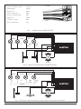
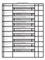
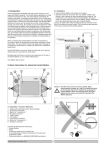
user manual
LokPilot V2.0
Art-No. 52600 / 52602
LokPilotDCC V2.0
Art-No. 52601/ 52603
Version 1.1, 1st edition
January 2005
user manual LokPilot V2.0 / LokPilot DCC V2.0 01/2005
1
General Features:
LokPilot V2.0 is the successor of the popular LokPilot
decoder. It enhances the already outstanding
properties with more features with the objective, to
improve running characteristics even more, to increase
reliability and flexibility.
LokPilot V2.0 is available in two types:
LokPilot V2.0 is a multi-protocol-decoder. It supports
Märklin / Motorola as well as the widely used DCC
system. It can also be used in analogue layouts with
AC or DC supply. Thus it is the ideal decoder even for
layouts with combined Motorola / DCC controls.
LokPilotDCC V2.0 is „thoroughbred“ DCC Decoder. It
provides all functions of LokPilot V2.0, except for the
Motorola-protocol and can also be used in analogue
mode (DC only).
Both decoders are the premier choice for the
demanding model train enthusiasts who insist on
excellent load control – particularly at low speeds –
and maximum flexibility in terms of adapting the
decoder to the model engine. LokPilot V2.0 detects
the operating mode automatically and can control
DC motors, coreless motors (e.g.: Faulhaber) or universal motors with HAMO-magnets. Due to its unique
features LokPilot V2.0 offers great flexibility and
reliability, as you have come to expect it from a top
quality decoder. Even future updates are no problem
for LokPilot V2.0: Due to its flash memory technology
it can be updated to the latest version at any time.
Properties of LokPilotDCC V2.0:
• Fully operational on analogue DC layouts
•Fully automatic change of operating mode (autodetect)
th
• 4 generation load control: to be adapted to motor
characteristics with three CVs
•40 kHz tact frequency for smooth and silent motor
control
• Supports Lenz Brake sections
• Improved function mapping: All outputs can be
assigned to any function button
• Lighting effects: Strobe, Double Strobe, Mars- und
Gyro light, Firebox, Blinker, Flash.
• 2 directional outputs for headlights for up to 180
mA each
• 2 auxiliary outputs (F1 und F2), for up to 180 mA
each
• Maximum total current of all 4 outputs: 350 mA
•Adjustable acceleration and maximum speed even
in analogue mode
• Motor output: maximum 1.1 A, over current guard
• Total maximum load of decoder: 1.2 Amps
•Dimensions: 23 x 15.5 x 6.5 mm
• Designed for the future due to possible firmware
upgrade with flash-memory
Additional features of LokPilot V2.0:
• Suitable for analogue AV layouts
• Supports Motorola-format (old and new)
• Programming mode for Märklin 6021 (for the most
important functions)
Important note:
• The LokPilot V2.0 and LokPilotDCC decoders are
designed for use in model railways only
• Avoid mechanical force and impact on the
decoder
• Do not expose to wet and humid conditions
• Do not remove the heat shrink sleeve around the
decoder
• Never solder on the circuit board, extend cables
if necessary
• Never wrap the decoder in insulation tape, since
this may cause overheating
• 14, 28 and 128 speed steps in DCC-mode
• Always disconnect the circuit when installing the
decoder
• Automatic detection of speed step setting inmost
DCC-systems
• Make sure that no blank wire ends come into
contact with any metal parts of the locomotive
• 2- or 4-digit address
• Make sure that no wires are squeezed or cut by
the model’s transmission parts when reassembling
the locomotive.
• Fully compatible with NMRA-standards
• Shunting speed
• Acceleration and deceleration can be switched off
• Advanced Consisting
• Freely selectable speed curve
2
user manual LokPilot V2.0 / LokPilot DCC V2.0 01/2005
Pin
Description
Colour code
1 motor connection right
2 backup light
orange
yellow
3
function F1
green
4
track connection 1
black
5
motor connection left
grey
6
light front
white
7
common (+pole)
blue
8
track connection 2
red
1 = orange
5 = grey
Fig. 1 - Interface as per NEM 650/652
green
violet
yellow
F1
F2
light
back
white
light
front
LokPilot
blue
black
red
orange
grey
engine
Fig. 2 - Wiring of LokPilot with isolated funktions
green
violet
F1
F2
yellow
withe
light
back
light
front
LokPilot
chassis
orange
balck
red
grey
engine
Fig. 3 - Wiring of LokPilot with the common pole connected to the chassis
user manual LokPilot V2.0 / LokPilot DCC V2.0 01/2005
3
Prior to installation
The locomotive must be in perfect technical condition
prior to installation. Only a locomotive with a troublefree mechanism and smooth running properties in
analogue mode should be converted for digital mode.
Wear and tear parts, such as motor brushes, wheel
contacts, light bulbs, etc. must be inspected and
cleaned or replaced if necessary.
All work has to be carried out with the locomotive
placed on a suitable base (not the track) and definitely
un-powered. Make sure there can never be any
electrical power applied to the loco during the
conversion – even inadvertently.
Locomotives with DCC Interface
The LokPilotDCC is equipped with an interface as per
NEM 650/652 (NMRA page 9.1/9.2 - see fig. 1). Installation in locomotives with interface is therefore
particularly easy:
• Remove the body from the chassis. Please refer to
the instructions provided with your locomotive!
• Remove the plug from the DCC socket. Please keep
it for later use.
•Insert the plug in such a way that pin 1 of the plug
(near the red / orange wires) is located next to the
point marked *, +, . or 1. Please take care to avoid
bending the pins. Do not rely on the assumption
that the wires have to lead from the socket in a
certain direction: only the position of pin 1
determines which way the plug has to be inserted.
• Locate the decoder at a suitable position within the
locomotive. Most modern models have sufficient
space for a decoder. Use double sided adhesive
tape or a small amount of hot glue.
a) If directional headlights and functions are isolated
from the locomotive body proceed as per figure 2.
b) Directional headlights and functions may be
connected with their common to the track voltage
(e.g. almost all Maerklin® -locomotives and older
Fleischmann or ROCO locomotives are wired like
that) as per figure 3.
• Connect the red wire to the right rail pickup (or
centre pick up in AC models),
• and the black wire to the left rail pickup (wheels in
AC models).
• Connect the orange wire with the motor terminal,
which was originally wired to the right wheel pick
up (centre pick up
in AC models).
• The grey wire goes to the terminal, which was
originally connected to the left rail (common rails
for AC models).
• Solder the back up lights to the yellow wire, the
front headlights to the white wire.
• Connect the green wire to the function output,
which you want to switch with function button F1.
• Connect the purple wire with the function output,
which you want to switch with the function button
F2.
If your locomotive is wired as per b) above, then wiring
is completed.
In the case as per fig. 2 you have to connect the
second pole of all light bulbs or other loads to the
blue wire. The blue wire must not be connected to
the chassis!
Connecting Auxiliary Functions
Locomotives without interface
First separate all wires in the locomotive and make
sure there is no hidden connection from one of the
motor terminals to the chassis or the wheel contacts.
The motor terminals definitely must be insulated.
Fleischmann models often have such a connection,
which can easily be overlooked. Check all connections
using an Ohmmeter and make sure there are no short
circuits between the motor terminals and the wheel
contacts.
How to proceed depends on how the headlights and
other functions are wired:
4
Any load may be connected to the light and
function outputs as long as it doesn’t exceed the
maximum current. Please note that the overload
protection of the decoder responds very quickly
and will switch off all functions immediately in case
of overload or short circuit.
Therefore use only 16 V bulbs or higher and a
maximum nominal current of 50 mA:
Incandescent lamps have a high starting current
and this may activate the overload protection of
the decoder when the lights are switched on.
user manual LokPilot V2.0 / LokPilot DCC V2.0 01/2005
Use only digital smoke generators (e.g. Seuthe No.
11) for locomotives whose light and function outputs
are connected as shown in figure 2. All other smoke
generators may draw too much current. Some
commercially available smoke generators have a higher
nominal current than 250 mA!
Locomotives that are connected as shown in figure 3
need an analogue smoke generator e.g.
Seuthe No. 10.
Make sure that the total current for all function
outputs does not exceed the permitted current
rating and avoid short circuits between outputs.
Although outputs of LokPilotDCC decoders are
protected, high voltage on the terminals or a
short circuit may damage the decoder!
Set-up and initial operation
Before replacing the body and reconnecting the
engine it is recommended to carry out a function
test.
The factory pre-set address is 03.
• Does the locomotive move in either direction?
• Turn the lights on: are they operating correctly? If
the LokPilotDCC V2.0 decoder is used in a
locomotive with NEM interface: check if the NEM
connector is plugged in correctly.
DCC-Mode
Remove capacitors that may be connected to the
track section (e.g. in ROCO connecting track). They
may impede normal operation of the decoder and
even destroy it.
LokPilotDCC may be operated with any DCC compatible
system. The automatic speed step detection was tested
with the following devices: ROCO Lokmaus2, Uhlenbrock Intellibox, Lenz Digital plus V2.3, ZIMO MX1.
When using Lenz digital plus V3.0 the auto-detect
feature does not operate in 14-speed step mode.
Change to 28/128 speed steps.
LokPilotDCC attempts to detect the speed step setting
every time the system is powered up and the lights
are turned on. In order to accomplish this you have
to switch on the lights and vary the speed setting
until the lights burn consistently. If you want to change
the speed step setting during operation, you have to
disconnect the circuit/track/locomotive to activate the
auto-detect feature
The auto-detect feature can be turned off with CV 49
Bit 4 (refer to the table on page 8).
user manual LokPilot V2.0 / LokPilot DCC V2.0 01/2005
Motorola-mode (not for LokPilotDCC V2.0)
The LokPilot V2.0 can be used with all Märklin® devices
or compatible systems previously sold or currently on
the market. The functions F1 to F4 can only be
activated with the so-called „new Motorola®format“. To activate this, the DIP switches 1 and 2 on
the 6021 have to be set to the upper position („On“).
Adjusting decoder parameters
The LokPilot V2.0 supports many parameters. A
detailed list is provided at the end of this manual. All
adjustable parameters are stored in so called CVs
(configuration variables). They can be adjusted
individually, depending on the type of command
station. Please refer to the relevant chapters in the
manual of your digital system (e.g.: programming of
DCC decoders). The LokPilot V2.0 supports all
programming methods as per NMRA.
Programming Märklin 6020 / 6021
Märklin central units 6020 and 6021 have to be dealt
with differently. Only parameters up to number 80
are available, provided the desired number is also below
80. Proceed as follow to adjust these
CVs (not for LokPilotDCC V2.0):
(The throttle must be set to 0. No other engines may
be on the layout. Take note of the blinking lights of
the engine!)
• Press the „Stop“- and „Go“-buttons of the 6021 at
the same time (simultaneously), until a Reset is
triggered. (alternatively pull the mains plug and replug afterwards)
• Press the „Stop“-button in order to turn off the
track voltage
• Enter the current decoder address (alternative:
„80“)
• Activate change of direction with the throttle (turn
the knob left over the „Stop“-position until you
hear a click), hold the knob there and press the
„Go“-button
• The LokPilot V2.0 is now in programming mode
(headlights are blinking)
• Enter the number of the parameter (CV) you want
to change (two digits).
• Confirm by pressing „change of direction“ (now
the headlights blink in double mode)
• Enter the new value for the register (two digits)
•Confirm by pressing „change of direction“
(headlight are on for 1 second and then start
blinking)
5
• Now you can change other register in the same
manner
• You exit the programming mode by selecting
register „80“ or by turning off the track voltage
for a moment (press „Stop“-button on 6021, then
„Go“-button)
Please note:
• The value „0“ can not be entered with 6021. Instead
you have to enter „80“.
• Only CVs from 01 to 80 can be changed.
• For adjusting CVs higher than 80 you have to use a
DCC-compatible command station.
• For easy and comfortable programming of ESU
decoders we recommend the ESU LokProgrammer
Nr. 53450. With its assistance you can comfortably
programm your LokPilot V2.0 on your PC. More
information regarding the ESU LokProgrammer can
be found on our website.
Tips und Tricks
Adjusting Load control
Decoder-Reset
You can easily reset the decoder by
writing the value 08 in CV 08 at any time.
Function mapping
The outputs can be assigned to any function button.
ESU utilises the so-called Enhanced Mapping with the
advantage that each function can be assigned to any
function button. Furthermore the assignment can
vary subject to direction of travel. It is also possible to
trigger several functions with one button
simultaneously. Each function button is assigned two
CVs per direction (so-called control CVs A, B,) to
determine the desired behaviour of each button.
Figure 4 on page 10 shows the possible combinations.
Generally it can be said:
• All function buttons are directional. If you change
the assignment of any function button, please do
so for both directions.
• Your digital system may not support all function
buttons.
The load control of the LokPilot V2.0 can be adapted
to different types of motors. The standard settings
match most motors very well but may have to be
adjusted for other models. This is particularly true for
coreless motors (Faulhaber, Maxxon) where we
recommend to set the K-value (CV 54) to a lower
value.
• Each physical output must be assigned to a function
button and also has to be „switched on“ initially.
Parameters for Fleischmann
Switching on function outputs
Locomotives with the traditional round motor by
Fleischmann should be programmed as follows:
Prior to use each function output can / must first be
switched on. Furthermore each output offers the
possibility to set one of 10 different lighting effects:
CV 54 = 14 - 18
CV 55 = 20
Parameters for Märklin® high performance
motors
The 5-pole high performance motor by Maerklin®
(series 37xxx) is best suited for the LokPilotDCC when
programmed as follows:
CV 54 = approx. 20 - 25
CV 55 = 38
Parameters for coreless motors
Later on we will show some examples to provide a
better understanding. Before we have to explain two
more properties of function outputs:
• Dimmer: normal, continous output
• Blinking: output blinks with adjustable frequency.
• Inverse blinking: Output blinks as before, but with
opposite timing. Thus alternate blinking lights can
be set.
• Strobe
• Double Strobe
• Random, Firebox
• Smoke, adjusting the intensity of the smoke
generator
CV 54 = approx. 4 - 10
• Zoom, high beam and dimmed lights
CV 55 = approx. 3 - 8
• Mars light
• Gyro light
6
user manual LokPilot V2.0 / LokPilot DCC V2.0 01/2005
There is one CV fro each output (CV 113 - 116), in
which the desired mode can be saved. Please note
that you can deactivate each output by setting it to 0
if it is not required. Ex works the lighting outputs are
set to „on“ and for steam engines AUX – 1 is to be
switched with the headlight button.
the column for function AUX 1 you will find a number
in the heading of this column. In our example it is a
„4“. This value has to be written into CV 171. Then
the F5 button controls AUX 1. Thus the function is
switched in forward mode. In order to also switch
this function in back up mode you have to enter the
same value in CV 174.
Adjust lamp brightness
The LokPilot V2.0 offers the feature to adjust the
brightness of lamps in 15 steps in order to adapt the
light intensity optimally to the specific model. The
lamps are supplied with pulses, i.e. they are switched
on and off very frequently. The desired brightness (0
– 15) must be set in the appropriate control CV (113
– 116) by adding it to the value corresponding with
the type of function.
Blinking frequency and duration of cycle
CV 112 determines the blinking frequency (subject to
the duration of the cycle) as well as the „on/off“ ration
for all outputs set to blinking.
The cycle can be set in 33 different steps. The cycle is
always a multiple of 65.5 milli seconds. The „on/off“
ratio can be set in 16 steps (from 1/16 to 16/16). At
a ratio of 8/16 the „on“ and „off“ period is equally
long. The value to be entered in control CVs 113 –
116 can be calculated as follows:
Cycle (value: 0-15) + 16 + On / Off ratios.
• Example 2
2:
Blinking light on AUX2 and F6.
A blinking light should be wired to AUX 2 and assigned
to the F6-button. The brightness is to be set to 6/15
of maximum brightness. The blinking cycle and on/
off ration are to be set as described above. First we
need to activate output AUX 2 and set it to blinking
mode. CV 116 is responsible for this. In our example
we enter 32 (for blinking mode) + 5 (corresponds to
6/15 of maximum brightness) = 37.
Now we have to assign AUX 2 to button F6. The
control CV 177 is responsible for F6. We enter in this
CV which functions should be switched with the F6
button. If you follow the row for „F6 forward“ in the
table in figure 4 to the right until it meets the column
for AUX 2 you find the number „8“ at the top of the
column. This value has to be entered into CV 177.
Now the F6 button switches AUX 2 in forward mode.
To also set the F6 button for back up mode, enter
value 8 in CV 183.
• Example 3
3:
Braking time On / Off with F5.
Examples:
• Example 1
1:
smoke generator on AUX 1 and F5.
Let’s assume you want to operate a smoke generator
with function button F5 and output AUX 1.
Output AUX 1 must be activated and the F5-button
has to be assigned:
First you activate the output; in this case we want a
continuous output (dimming setting at 100%
brightness). CV 115 is responsible for this output. The
value to be entered in CV 115 has to be calculated as
follows: 15 for maximum brightness.
Now the function button has to be assigned to output
AUX 1: Have a look at figure 4: Control CV 171 is
responsible for button F5 in forward mode (third
column). You have to enter in CV 171 which functions
should be triggered with F5. If you follow the row for
F5 in the table in figure 4 to the right until it meets
user manual LokPilot V2.0 / LokPilot DCC V2.0 01/2005
Acceleration / deceleration should be controlled with
F5. Since acceleration / deceleration does not represent
a physical output but rather a logical output this
function does not have to be configured. Only the
button F5 has to be assigned to acceleration /
deceleration. This is done with CV 172 where you
enter the value „1“ (also refer to figure ??). If this
function should also work in back up mode value „1“
has to be entered in CV 175. For configuring function
outputs we recommend using your PC and the ESU
LokProgrammer.
The LokPilot V2.0 decoder offers many possibilities
and combinations of functions and therefore a PC
and the ESU LokProgrammer (Art. No.: 53450) are
extremely useful for programming.
7
Settings for analogue mode
Support and Assistance
With the aid of CVs 125 and 126 you can adjust the
starting and maximum speed for analogue DCoperation. In analogue AC operation CVs 127 and
128 are responsible (not for LokPilotDCC V2.0). Thus
you can adjust the various speed settings even in
analogue operation.
Your first port of call with any questions is the dealer
where you purchased the LokPilot V2.0 decoder. He
is your competent partner for all your questions related
to the model train hobby.
LGB-control
When using LGB-command stations or the Roco Lokmaus I the LokPilot V2.0 can be set to pulse control.
Set bit 5 in CV 49 for this purpose. Subsequently the
decoder counts the number of times the F1 button is
pressed in sequence in order to be activated the desired
function. Thus you can trigger all available functions
by pressing the F1 button the appropriate number of
times.
Brake sections
You may also contact us directly. For enquiries please
use either email or fax (don’t forget to provide your
own fax-no.) and we will reply within a few days.
Please call our hotline only in case of complex
enquiries that can’t be dealt with by email or fax.
The hotline is often very busy and you may
encounter delays. Also check our website for more
information. You will find many hints under „Support / FAQ“ and even feed back from other users.
The LokPilot V2.0 decoder supports the most
commonly used brake systems:
• Lenz-Brake generator in DCC-mode
Of course we will be pleased to assist you. You can
contact us at:
• Märklin® Brake section (not LokPilotDCC V2.0)
As soon as a brake command is recognised the LokPilot
V2.0 decoder slows down the engine with the
deceleration set in CV 4. After the enforced stop the
engine accelerates as per the setting in CV 3. In order
to active this feature certain settings have to be entered in CV 51.
By telephone: ++49 (0)700 – LOKSOUND
++49 (0)700 – 56576863
Tuesdays:
from 10.00 am to 12.00 noon
Wednesdays:
Lenz Brake generator
The Lenz LG100 works in compliance with the
mechanisms described by the NMRA and is fully
supported by the LokPilot V2.0 decoder. Write value
8 in CV 51.
from 10.00 am to 12.00 noon
Per Fax:
++49 (0)700 - 37872538
Per email:
[email protected]
Per mail:
ESU electronic solutions ulm GmbH
- Technical Support Industriestraße 5/2
Märklin®-Brake section
In principle the Märklin®-Bake section applies DC to
the track instead of the digital signals. In order to
activate this mode the value 1 has to be written in CV
51. The Märklin®-Brake section and the analogue DC
operation should never be active at the same time,
because the DC supply of the Märklin® Brake section
could be interpreted as analogue DC-mode. Turn off
the analogue mode in CV 50 to avoid this. The Märklin
Brake section is not available for the LokPilotDCC V2.0.
8
D-89081 Ulm
Internet: http://www.loksound.de
user manual LokPilot V2.0 / LokPilot DCC V2.0 01/2005
F0
F0
F1
F1
F2
F2
F3
F3
F4
F4
F5
F5
F6
F6
F7
F7
F8
F8
F9
F9
F10
F10
F11
F11
F12
F12
Description
value
stand forward
stand backward
drive forward
drive backward
light forward
light backward
key F1forward
key F1 backward
key F2 forward
key F2 backward
key F3 forward
key F3 backward
key F4 forward
key F4 backward
key F5 forward
key F5 backward
key F6 forward
key F6 backward
key F7 forward
key F7 backward
key F8 forward
key F8 backward
key F9 forward
key F9 backward
key F10 forward
key F10 backward
key F11 forward
key F11 backward
key F12 forward
key F12 backward
129
132
135
138
141
144
147
150
153
156
159
162
165
168
171
174
177
180
183
186
189
192
195
198
201
204
207
210
213
216
Headlight
1
1
Back-up lights
2
2
AUX 1
4
4
4
AUX 2
8
8
8
16
32
64
128
Control CV B
value
130
133
136
139
142
145
148
151
154
157
160
163
166
169
172
175
178
181
184
187
190
193
196
199
202
205
208
211
214
217
Acceerationl on / off
1
1
1
Shunting modeon / off
2
2
2
Fig. 4
Function Mapping
user manual LokPilot V2.0 / LokPilot DCC V2.0 01/2005
9
Control CV A
Function button
List of all supported CVs
CV Name
Description
Range
default value
1
Address
address of locomotive
1 – 127
3
2
Starting voltage
determines the starting speed
1 – 75
3
3
Acceleration
This value multiplied by 0.869 gives the time
from stop to maximum speed
0 – 64
8
4
Deceleration
This value multiplied by 0.869 gives the time
from maximum speed to stop
0 – 64
6
5
Maximum speed
maximum speed of locomotive
0 - 64
64
6
Medium speed
Speed of locomotive at medium speed step
0 - 64
22
7
Version number
Internal software version of LokPilotDCC (read only)
-
8
Manufacturer’s ID
Manufacturer’s identity (ID) of ESU
Writing value 8 triggers a reset of all
CVs to factory values
13 Analogue mode F1-F8 Setting of functions F1 to F8 in analogue mode
Bit Function
0-255
1
0-255
3
Long address of locomotive
128 -
192
CV 17 contains the higher value Byte (Bit 6 and
9999
0 Function F1.
14 Analogue Mode FL,
F9-F12
1
2
2 Function F3
4
3 Function F4
8
4 Function F5
16
5 Function F6
32
6 Function F7
64
7 Function F8
128
Setting of functions FL, F9 to F12 in
analogue mode
Value
0 Function FL(f)
1
1 Function FL(r)
2
2 Function F9(f)
4
3 Function F10(f)
8
4 Function F11
16
5 Function F12
32
6 Function F9(r)
64
7 Function F10(r)
18 address
Value
1 Function F2.
Bit Function
17 Extended locomotive
151
128
Bit 7 must always be active), CV 18 contains the
Lower value Byte. Only active, if feature
is switched on in CV 29 (see below)
10
user manual LokPilot V2.0 / LokPilot DCC V2.0 01/2005
List of all supported CVs
CV Name
19 Consist address
Description
Range
Additional address for consist operation
0 – 127
Value 0 or 128 means: Consist address inactive
1 – 127 consist address for normal direction of travel
129 – 255 consist address for reversed direction of travel
29 Configuration register The most complex CV within the DCC standards. -
default value
0
4
This register contains important information,
most of which is only available in DCC mode.
Bit Function
0 Reverse direction of travel
(forward becomes reverse)
normal direction of travelreversed directional properties
1 speed step system (DCC-mode only)
14 speed steps
28 or 128 speed steps
2 Analogue mode
Analogue mode off
Analogue mode permitted
4 Selection of speed curve
speed curve through CV 2, 5, 6
speed curve through CV 67 - 96
5 Selection of address (DCC-mode only)
short addresses (CV 1) in DCC-mode
Long addresses (CV 17+18) in DCC-mode
user manual LokPilot V2.0 / LokPilot DCC V2.0 01/2005
Value
0
1
0
2
0
4
0
16
0
32
11
List of all supported CVs
CV Name
49 Expanded
Configuration
Description
Range
Here you can active support for Brake sections
or turn off load control
Bit Description
50 Analogue mode
19
Value
0 Load control active
Load control off
1
0
1 DC Motor PWM frequency
20 kHz Tact frequency on
40 kHz Tact frequency on
0
2
2 Märklin Delta Mode
Delta Mode off
Delta Mode on
0
4
3 Märklin 2. address
Märklin 2. address off
Märklin 2. address on
0
8
4 Automatic speed step detection
speed step detection in DCC mode off
speed step detection DCC mode on
0
16
5 LGB Function button mode
LGB Mode off
LGB Mode on
0
32
6 ZIMO Manual function
ZIMO Manual function off
ZIMO Manual function on
0
64
Determines which analogue modes are permitted
Bit Function
51 Brake mode
default value
0-3
3
Value
0 AC Analogue mode
AC Analogue mode off
AC Analogue mode on
0
1
1 DC Analogue mode
DC Analogue mode off
DC Analogue mode on
0
2
Determines which brake modes are permitted
Bit Function
4
Value
0 Märklin Brake mode
Märklin Brake mode off
Märklin Brake mode on
0
1
1 ZIMO Brake mode
ZIMO Brake mode off
ZIMO Brake mode on
0
2
2 not used
3 Lenz DCC Brake mode
Lenz Brake mode off
Lenz Brake mode on
12
0
8
user manual LokPilot V2.0 / LokPilot DCC V2.0 01/2005
List of all supported CVs
CV Name
53 Control reference
Description
Determines the back EMF that the motor
should supply at maximum speed. The more efficient
the motor, the higher this value may be. Reduce
this value if the engine does not reach its designed .
maximum speed
Range
0 - 80
54 Load control
parameter K
„K“-component of the internal PI-controller.
0 - 80
Determines how strongly load control effects.
The higher the value, the stronger the impact on the motor.
32
55 Load control
parameter I
„I“-component of the internal PI-controller.
Determines the momentum of the motor.
Motors with large flywheels of large diameter require
a smaller value.
0 - 80
24
56 Load control influence 0 – 100 %
Determines up to how many % of the speed load
control is active. At a value of 32 load control will be
switched off , half the maximum speed is reached.
1 - 64
64
66 Forward trim
Divided by 128 results in the factor, with which the
motor voltage is multiplied in forward mode.
The value 0 deactivates the trim.
0 - 255
0
67- Speed table
94
Assigns a motor voltage to the speed steps.
Values in between will be interpolated.
0 – 255
—
95 Back up trim
Divided by 128 results in the factor, with which the
motor voltage is multiplied in forward mode.
The value 0 deactivates the trim.
0 - 255
0
112Blinking frequency
Frequency of Strobe effects.
always a multiple of 65,536 ms
4 - 64
33
0 – 255
15
113Output configuration Function of output Headlights (forward)
Headlights (forward)
Description
Value
Continous output (dimmer)
Vol
Blinking output (Phase 1)
Vol + 16
Blinking output (Phase 2)
Vol + 32
Strobe
Vol + 48
Double Strobe
Vol + 64
Firebox
Vol + 80
Smoke generator
default value
56
Vol + 96
Headlights (high beam / low beam
Vol + 112
Mars light
Vol + 128
Gyro light
Vol + 144
Vol = brightness. Range 0 (dark) - 15 (maximum)
user manual LokPilot V2.0 / LokPilot DCC V2.0 01/2005
13
List of all supported CVs
CV Name
Description
Range
114 Output configuration Function of output Back up lights (reverse)
Back up lights
Description
default value
0 - 255
15
0 - 255
15
Value
Continous output (dimmer)
Blinking output (Phase 1)
Vol
Vol + 16
Blinking output (Phase 2)
Vol + 32
Strobe
Vol + 48
Double Strobe
Vol + 64
Firebox
Vol + 80
Smoke generator
Vol + 96
Headlights (high beam / low beam
Vol + 112
Mars light
Vol + 128
Gyro light
Vol + 144
Vol = brightness. Range 0 (dark) - 15 (maximum)
115 Output configuration Function of output AUX 1
AUX 1
Description
Value
Continuous output (dimmer)
Blinking output (Phase 1)
Vol
Vol + 16
Blinking output (Phase 2)
Vol + 32
Strobe
Vol + 48
Double Strobe
Vol + 64
Firebox
Vol + 80
Smoke generator
Vol + 96
Headlights (high beam / low beam
Vol + 112
Mars light
Vol + 128
Gyro light
Vol + 144
Vol = brightness. Range 0 (dark) - 15 (maximum)
14
user manual LokPilot V2.0 / LokPilot DCC V2.0 01/2005
List of all supported CVs
CV Name
Description
Range
116Output configuration Function of output AUX 2
AUX 2
Description
0 - 255
Value
Continous output (dimmer)
default value
15
Vol
Blinking output (Phase 1)
Vol + 16
Blinking output (Phase 2)
Vol + 32
Strobe
Vol + 48
Double Strobe
Vol + 64
Firebox
Vol + 80
Smoke generator
Vol + 96
Headlights (high beam / low beam
Vol + 112
Mars light
Vol + 128
Gyro light
Vol + 144
Vol = brightness. Range 0 (dark) - 15 (maximum)
124Data memory
Determines, which data are to be saved and used
after an interruption of the power supply.
Bit Function
0 Saves the direction of travel
0 - 15
7
Value
1
1 Saves the status of function buttons
2
2 Saves the current speed setting
4
3 Accelerates after a reset with the
programmed acceleration
8
125
Analogue DC starting voltage
0-127
110
126
Analogue DC maximum speed
0-127
127
127
Analogue AC starting voltage
0-127
50
128
Analogue AC maximum speed
0-127
127
129Assignment of
function buttons
Assignment of function outputs
to be active in status standstill - forward
0 – 255
0
0 – 255
0
Standstill – forward A Bit Description
130Assignment of
function buttons
Standstill – forward B
Value
0 Headlights (forward)
1
1 Back up lights (reverse)
2
2 Auxiliary function AUX 1
4
3 Auxiliary function AUX 2
8
Assignment of function outputs
to be active in status standstill - forward
Bit Description
Value
0 Acceleration on / off
1
1 Shunting speed on / off
2
user manual LokPilot V2.0 / LokPilot DCC V2.0 01/2005
15
List of all supported CVs
CV Name
132Assignment of
function buttons
Standstill – back up A
133Assignment of
Range
Assignment of function outputs
to be active in status standstill – back up
Bit Description
1
1 Back up light
2
2 Auxiliary function AUX 1
4
3 Auxiliary function AUX 2
8
Assignment of function outputs
to be active in status standstill – back up
Standstill – back up B
Bit Description
Forward A
136Assignment of
0 Acceleration on / off
1
1 Shunting speed on / off
2
Assignment of function outputs
to be active in forward mode
Bit Description
0 Headlight (forward)
1
1 Back up light
2
2 Auxiliary function AUX 1
4
3 Auxiliary function AUX 2
8
Assignment of function outputs
Forward B
Bit Description
139Assignment of
function buttons
Back up B
0
0 - 255
0
0 - 255
0
0 - 255
0
0 - 255
0
0 - 255
0
Value
to be active in forward mode
Back up A
0 - 255
Value
function buttons
138Assignment of
function buttons
default value
Value
0 Headlight (forward)
function buttons
135Assignment of
function buttons
16
Description
Value
0 Acceleration on / off
1
1 Shunting speed on / off
2
Assignment of function outputs
to be active in back up mode
Bit Description
Value
0 Headlight (forward)
1
1 Back up light
2
2 Auxiliary function AUX 1
4
3 Auxiliary function AUX 2
8
Assignment of function outputs
to be active in back up mode
Bit Description
Value
0 Acceleration on / off
1
1 Shunting speed on / off
2
user manual LokPilot V2.0 / LokPilot DCC V2.0 01/2005
List of all supported CVs
CV Name
141Assignment of
headlight button
Forward A
142Assignment of
headlight button
Forward B
144Assignment of
Description
Bit Description
1
1 Back up light
2
2 Auxiliary function AUX 1
4
3 Auxiliary function AUX 2
8
Assignment of function outputs
to headlights to be active in forward mode
Bit Description
Acceleration on / off
1
1
Shunting speed on / off
2
Assignment of function outputs
Back up A
Bit Description
Back up B
147Assignment of
function button F1
Forward A
148Assignment of
function button F1
Forward B
1
1 Back up light
2
2 Auxiliary function AUX 1
4
3 Auxiliary function AUX 2
8
Assignment of function outputs
to headlights to be active in back up mode
Bit
Description
0
Acceleration on / off
1
1
Shunting speed on / off
2
0 - 255
2
0 - 255
0
0 - 255
4
0 - 255
0
Value
1
1 Back up light
2
2 Auxiliary function AUX 1
4
3 Auxiliary function AUX 2
8
Value
0 Acceleration on / off
1
1 Shunting speed on / off
2
user manual LokPilot V2.0 / LokPilot DCC V2.0 01/2005
0
Value
0 Headlight (forward)
Assignment of function outputs
to F1 to be active in forward mode
Bit Description
0 - 255
Value
0 Headlight (forward)
Assignment of function outputs
to F1 to be active in forward mode
Bit Description
1
Value
0
to headlights to be active in back up mode
default value
0 - 255
Value
0 Headlight (forward)
headlight button
145Assignment of
headlight button
Range
Assignment of function outputs
to headlights to be active in forward mode
17
List of all supported CVs
CV Name
150Assignment of
Description
Range
Assignment of function output
function button F1
Back up A
to F1 to be active in back up mode
Bit Description
0 Headlight (forward)
1 Back up light
2 Auxiliary function AUX 1
3 Auxiliary function AUX 2
151Assignment of
function button F1
Assignment of function outputs
to F1 to be active in back up mode
Back up B
153Assignment of
function button F2
to F2 to be active in forward mode
Forward A
Bit
0
154Assignment of
function button F2
Forward B
156Assignment of
function button F2
Back up A
157Assignment of
function button F2
Back up B
159Assignment of
function button F3
Forward A
160Assignment of
function button F3
Forward B
162Assignment of
function button F3
Back up A
163Assignment of
function button F3
Back up B
18
Bit Description
0 Acceleration on / off
1 Shunting speed on / off
Assignment of function outputs
Description
refer to CV 147
4
0 - 255
4
0 - 255
8
0 - 255
0
0 - 255
8
Value
1
2
Value
Description
refer to CV 148
Value
Assignment of function outputs
to F2 to be active in back up mode
Bit
0
0 - 255
Value
1
2
4
8
Assignment of function outputs
to F2 to be active in forward mode
Bit
0
Description
refer to CV 150
Value
Assignment of function outputs to F2 to be active in back up mode
Bit
0
Description
refer to CV 151
Description
refer to CV 147
Description
refer to CV 148
Description
refer to CV 150
Description
refer to CV 151
0 - 255
2
0 - 255
0
0 - 255
2
Value
Assignment of function outputs
to F3 to be active in back up mode
Bit
0
0
Value
Assignment of function outputs
to F3 to be active in back up mode
Bit
0
0 - 255
Value
Assignment of function outputs
to F3 to be active in forward mode
Bit
0
0
Value
Assignment of function outputs
to F3 to be active in forward mode
Bit
0
default value
Value
user manual LokPilot V2.0 / LokPilot DCC V2.0 01/2005
List of all supported CVs
CV Name
165Assignment of
function button F4
Forward A
166Assignment of
Description
Bit
0
Description
refer to CV 147
to F4 to be active in forward mode
Forward B
Bit
0
Description
refer to CV 148
to F4 to be active in back up mode
Back up A
Bit
0
169Assignment of
Description
refer to CV 150
to F4 to be active in back up mode
Back up B
Bit
Description
0
refer to CV 151
171Assignment of
function button F5
Forward A
172Assignment of
function button g F5
Forward B
174Assignment of
function button F5
Back up A
175Assignment of
Description
0
refer to CV 147
Description
0
refer to CV 148
Description
refer to CV 150
to F5 to be active in back up mode
Back up B
Bit
Description
0
refer to CV 151
177Assignment of
function button F6
Forward A
0
Description
1
0 - 255
0
0 - 255
0
0 - 255
0
0 - 255
0
0 - 255
0
Value
Assignment of function outputs
to F6 to be active in forward mode
Bit
0 - 255
Value
Assignment of function outputs
function button F5
0
Value
Assignment of function outputs
to F5 to be active in back up mode
Bit
0
0 - 255
Value
Assignment of function outputs
to F5 to be active in forward mode
Bit
1
Value
Assignment of function outputs
to F5 to be active in forward mode
Bit
0 - 255
Value
Assignment of function outputs
function button F4
0
Value
Assignment of function outputs
function button F4
default value
0 - 255
Value
Assignment of function outputs
function button F4
168Assignment of
Range
Assignment of function outputs
to F4 to be active in forward mode
Value
refer to CV 147
user manual LokPilot V2.0 / LokPilot DCC V2.0 01/2005
19
List of all supported CVs
CV Name
178Assignment of
function button F6
180Assignment of
Range
Assignment of function outputs
to F6 to be active in forward mode
Bit
Description
0
refer to CV 148
Back up A
Bit
Description
0
refer to CV 150
183Assignment of
function button F7
Forward A
184Assignment of
function button F7
Forward B
186Assignment of
function button F7
Back up A
187Assignment of
function button F7
Back up B
189Assignment of
function button F8
Forward A
190Assignment of
function button F8
Forward B
Description
0
refer to CV 151
Description
0
refer to CV 147
Description
0
refer to CV 148
Bit
Description
0
refer to CV 150
0
refer to CV 151
Description
0
refer to CV 147
Description
0
refer to CV 148
0
255
0
255
0
255
0
255
0
255
0
Value
Assignment of function outputs
to F8 to be active in forward mode
Bit
255
Value
Assignment of function outputs
to F8 to be active in forward mode
Bit
0
Value
Assignment of function outputs
to F7 to be active in back up mode
Description
0 - 255
Value
Assignment of function outputs
to F7 to be active in back up mode
Bit
0
Value
Assignment of function outputs
to F7 to be active in forward mode
Bit
0 - 255
Value
Assignment of function outputs m
to F7 to be active in forward mode
Bit
0
Value
Assignment of function outputs er
to F6 to be active in back up mode
Bit
0 - 255
Forward B
Assignment of function outputs
to F6 to be active in back up mode
Back up B
default value
Value
function button F6
181Assignment of
function button F6
20
Description
Value
user manual LokPilot V2.0 / LokPilot DCC V2.0 01/2005
List of all supported CVs
CV Name
192Assignment of
function button F8
Back up A
193Assignment of
function button F8
Back up B
195Assignment of
function button F9
Forward A
196Assignment of
function button F9
Forward B
198Assignment of
Description
Assignment of function outputs
to F8 to be active in back up mode
Bit
Description
0
refer to CV 150
Bit
Description
0
refer to CV 151
Description
refer to CV 147
Description
0
refer to CV 148
to F9 to be active in back up mode
Bit
0
Back up B
201Assignment of
function button F10
Forward A
202Assignment of
function button F10
Forward B
204Assignment of
function button F10
Back up A
205Assignment of
Description
refer to CV 150
Description
0
refer to CV 151
Description
0
refer to CV 147
Description
0
refer to CV 148
Description
refer to CV 150
to F10 to be active in back up mode
Back up B
Bit
0
Description
refer to CV 151
user manual LokPilot V2.0 / LokPilot DCC V2.0 01/2005
0
255
0
255
0
255
0
255
0
255
0
255
0
Value
Assignment of function outputs
function button F10
255
Value
Assignment of function outputs
to F10 to be active in back up mode
Bit
0
0
Value
Assignment of function outputs
to F10 to be active in forward mode
Bit
255
Value
Assignment of function outputs
to F10 to be active in forward mode
Bit
0
Value
Assignment of function outputs
to F9 to be active in back up mode
Bit
255
Value
Assignment of function outputs
Back up A
0
Value
Assignment of function outputs
to F9 to be active in forward mode
Bit
255
Value
Assignment of function outputs
to F9 to be active in forward mode
Bit
0
default value
Value
Assignment of function outputs
to F8 to be active in back up mode
function button F9
199Assignment of
function button g F9
Range
Value
21
CV Name
207Assignment of
function button F11
Forward A
208Assignment of
function button F11
Forward B
210Assignment of
function button F11
Back up A
211Assignment of
function button F11
Back up B
213Assignment of
function button F12
Forward s A
214Assignment of
function button F12
Forward B
216Assignment of
function button F12
Back up A
List of all supported CVs
Description
Assignment of function outputs
to F11 to be active in forward mode
Bit
Description
0
refer to CV 147
Bit
Description
0
refer to CV 148
Description
0
refer to CV 150
Bit
Description
0
refer to e CV 151
Description
refer to CV 147
Description
0
refer to CV 148
Back up B
22
255
0
255
0
255
0
255
0
255
0
Value
Assignment of function outputs
to F12 to be active in back up mode
Bit
0
Value
Assignment of function outputs
to F12 to be active in forward mode
Bit
255
Value
Assignment of function outputs
to F12 to be active in forward mode
0
0
Value
Assignment of function outputs
to F11 to be active in back up mode
Bit
255
Value
Assignment of function outputs
to F11 to be active in back up mode
Bit
default value
Value
Assignment of function outputs
to F11 to be active in forward mode
0
217Assignment of
function button F12
Range
Description
Value
refer to CV 150
Assignment of function outputs
to F12 to be active in back up mode
Bit
Description
0
refer to CV 151
255
0
Value
user manual LokPilot V2.0 / LokPilot DCC V2.0 01/2005
Copyright 1998 - 2005 by ESU electronic solutions ulm GmbH & Co KG. Electrical characteristics and dimensions
are subject to change without prior notice. All rights reserved. ESU may not be held responsible for any damage
or consequential loss or damage caused by inappropriate use of the product, abnormal operating conditions,
unauthorized modifications to the product, etc.
Not suitable for children under 3 years of age. Inappropriate use may result in injury due to sharp points and
edges.
Märklin® is a registered trademark of the company Gebr. Märklin® und Cie. GmbH, Göppingen, Germany.
user manual LokPilot V2.0 / LokPilot DCC V2.0 01/2005
23
24
user manual LokPilot V2.0 / LokPilot DCC V2.0 01/2005