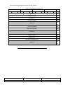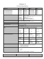
1
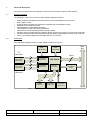
CCII Systems (Pty) Ltd Registration No. 1990/005058/07
C ommunications
C omputer I ntellig ence
I nteg ration
Hardware Reference and Installation Manual
for the
C²I² Systems
Dual 4 Gbps Fibre Channel PMC Adapter
C²I² Systems Document No.
CCII/FC/6-MAN/005
Document Issue
1.0
Issue Date
2009-01-19
Print Date
2009-01-19
File Name
P:\Fibrechn\TECH\MAN\CFCMAN05.WPD
Distribution List No
© C²I² Systems The copyright of this document is the property of C²I² Systems. The document is issued for the sole
purpose for which it is supplied, on the express terms that it may not be copied in whole or part, used by
or disclosed to others except as authorised in writing by C²I² Systems.
Document prepared by [and for] C²I² Systems, Cape Town
Amendment History
Issue
Description
Date
ECP No.
0.1
Initial Revision.
2009-01-09
-
1.0
Baseline.
2009-01-19
-
CCII/FC/6-MAN/005
P:\Fibrechn\TECH\MAN\CFCMAN05.WPD
2009-01-19
Issue 1.0
Page iii of v
Contents
1.
Scope . . . . . . . . . . . . . . . . . . . . . . . . . . . . . . . . . . . . . . . . . . . . . . . . . . . . . . . . . . . . . . . . . . . 2
1.1
1.2
1.3
2.
Applicable and Reference Documents . . . . . . . . . . . . . . . . . . . . . . . . . . . . . . . . . . . . . . . . . 3
2.1
2.2
3.
3.3
PMC Connectors . . . . . . . . . . . . . . . . . . . . . . . . . . . . . . . . . . . . . . . . . . . . . . . . . . . . . . . . . . . . . . . . . . . . . 9
SFF Fibre Optic Transceivers . . . . . . . . . . . . . . . . . . . . . . . . . . . . . . . . . . . . . . . . . . . . . . . . . . . . . . . . . . . 9
Hardware Installation . . . . . . . . . . . . . . . . . . . . . . . . . . . . . . . . . . . . . . . . . . . . . . . . . . . . . . 10
5.1
5.2
5.3
6.
Hardware Features . . . . . . . . . . . . . . . . . . . . . . . . . . . . . . . . . . . . . . . . . . . . . . . . . . . . . . . . . . . . . . . . . . . 4
Architecture . . . . . . . . . . . . . . . . . . . . . . . . . . . . . . . . . . . . . . . . . . . . . . . . . . . . . . . . . . . . . . . . . . . . . . . . . 4
3.2.1 PMC Interface . . . . . . . . . . . . . . . . . . . . . . . . . . . . . . . . . . . . . . . . . . . . . . . . . . . . . . . . . . . . . . . . . 5
3.2.2 Serial EEPROM . . . . . . . . . . . . . . . . . . . . . . . . . . . . . . . . . . . . . . . . . . . . . . . . . . . . . . . . . . . . . . . 5
3.2.3 Embedded Processor . . . . . . . . . . . . . . . . . . . . . . . . . . . . . . . . . . . . . . . . . . . . . . . . . . . . . . . . . . . 5
3.2.4 SSRAM Memory . . . . . . . . . . . . . . . . . . . . . . . . . . . . . . . . . . . . . . . . . . . . . . . . . . . . . . . . . . . . . . . 6
3.2.5 Flash ROM . . . . . . . . . . . . . . . . . . . . . . . . . . . . . . . . . . . . . . . . . . . . . . . . . . . . . . . . . . . . . . . . . . . 6
3.2.6 Small Form-factor (SFF) Fibre Optic Transceivers . . . . . . . . . . . . . . . . . . . . . . . . . . . . . . . . . . . . . 6
3.2.7 Indicators . . . . . . . . . . . . . . . . . . . . . . . . . . . . . . . . . . . . . . . . . . . . . . . . . . . . . . . . . . . . . . . . . . . . 6
General Features Description . . . . . . . . . . . . . . . . . . . . . . . . . . . . . . . . . . . . . . . . . . . . . . . . . . . . . . . . . . . 8
3.3.1 Simple Auto Speed Negotiation . . . . . . . . . . . . . . . . . . . . . . . . . . . . . . . . . . . . . . . . . . . . . . . . . . . 8
3.3.2 Redundant Management . . . . . . . . . . . . . . . . . . . . . . . . . . . . . . . . . . . . . . . . . . . . . . . . . . . . . . . . 8
3.3.3 Diagnostics . . . . . . . . . . . . . . . . . . . . . . . . . . . . . . . . . . . . . . . . . . . . . . . . . . . . . . . . . . . . . . . . . . . 8
3.3.4 Link Controllers . . . . . . . . . . . . . . . . . . . . . . . . . . . . . . . . . . . . . . . . . . . . . . . . . . . . . . . . . . . . . . . . 8
I/O Interface Description . . . . . . . . . . . . . . . . . . . . . . . . . . . . . . . . . . . . . . . . . . . . . . . . . . . . 9
4.1
4.2
5.
Applicable Documents . . . . . . . . . . . . . . . . . . . . . . . . . . . . . . . . . . . . . . . . . . . . . . . . . . . . . . . . . . . . . . . . . 3
Reference Documents . . . . . . . . . . . . . . . . . . . . . . . . . . . . . . . . . . . . . . . . . . . . . . . . . . . . . . . . . . . . . . . . . 3
Functional Description . . . . . . . . . . . . . . . . . . . . . . . . . . . . . . . . . . . . . . . . . . . . . . . . . . . . . 4
3.1
3.2
4.
Identification . . . . . . . . . . . . . . . . . . . . . . . . . . . . . . . . . . . . . . . . . . . . . . . . . . . . . . . . . . . . . . . . . . . . . . . . . 2
System Overview . . . . . . . . . . . . . . . . . . . . . . . . . . . . . . . . . . . . . . . . . . . . . . . . . . . . . . . . . . . . . . . . . . . . . 2
Document Overview . . . . . . . . . . . . . . . . . . . . . . . . . . . . . . . . . . . . . . . . . . . . . . . . . . . . . . . . . . . . . . . . . . . 2
The Adapter Kit . . . . . . . . . . . . . . . . . . . . . . . . . . . . . . . . . . . . . . . . . . . . . . . . . . . . . . . . . . . . . . . . . . . . . 10
Handling Instructions . . . . . . . . . . . . . . . . . . . . . . . . . . . . . . . . . . . . . . . . . . . . . . . . . . . . . . . . . . . . . . . . . 10
Installation of the Adapter . . . . . . . . . . . . . . . . . . . . . . . . . . . . . . . . . . . . . . . . . . . . . . . . . . . . . . . . . . . . . 10
5.3.1 Step 1. Prepare the Host Carrier Card (HCC) . . . . . . . . . . . . . . . . . . . . . . . . . . . . . . . . . . . . . . . 10
5.3.2 Step 2. Install the Adapter onto Host Carrier Card . . . . . . . . . . . . . . . . . . . . . . . . . . . . . . . . . . . . 10
5.3.3 Step 3. Securing the FC Adapter . . . . . . . . . . . . . . . . . . . . . . . . . . . . . . . . . . . . . . . . . . . . . . . . . 11
5.3.4 Step 4. Attach the Fibre Optic Cabling . . . . . . . . . . . . . . . . . . . . . . . . . . . . . . . . . . . . . . . . . . . . . 11
Programming Interface . . . . . . . . . . . . . . . . . . . . . . . . . . . . . . . . . . . . . . . . . . . . . . . . . . . . 13
6.1
6.2
6.3
PMC Addressing . . . . . . . . . . . . . . . . . . . . . . . . . . . . . . . . . . . . . . . . . . . . . . . . . . . . . . . . . . . . . . . . . . . . 13
Multifunction PMC . . . . . . . . . . . . . . . . . . . . . . . . . . . . . . . . . . . . . . . . . . . . . . . . . . . . . . . . . . . . . . . . . . . 13
Host Interface Registers . . . . . . . . . . . . . . . . . . . . . . . . . . . . . . . . . . . . . . . . . . . . . . . . . . . . . . . . . . . . . . 13
Annexure A . . . . . . . . . . . . . . . . . . . . . . . . . . . . . . . . . . . . . . . . . . . . . . . . . . . . . . . . . . . . . . . . 15
Functional Specifications . . . . . . . . . . . . . . . . . . . . . . . . . . . . . . . . . . . . . . . . . . . . . . . . . . . . . . . . . . . . . . . . . . . . 15
CCII/FC/6-MAN/005
P:\Fibrechn\TECH\MAN\CFCMAN05.WPD
2009-01-19
Issue 1.0
Page iv of v
Abbreviations and Acronyms
ANSI
API
ASIC
BER
CCII
CMC
CPU
EEPROM
EMC
END
FC
FC-AL-2
FCP
Gbps
HCC
I/O
ID
INT
IOC
IP
Kb
LC
MB
MHz
MPI
nm
OS
PC
PCB
PCI
PCI-X
PMC
RAM
ROM
SCSI
SFF
SIG
SSRAM
TCP
TCP/IP
VPD
WWN
x86
American National Standards Institute
Application Programming Interface
Application Specific Integrated Circuit
Bit Error Rate
C²I² Systems
Common Mezzanine Card
Central Processing Unit
Electrically Erasable Programmable Read Only Memory
Electromagnetic Compatibility
Enhanced Network Device
Fibre Channel
Fibre Channel Second Generation Arbitrated Loop
Fibre Channel Protocol
Gigabit per second
Host Carrier Card
Input / Output
Identification
Interrupt
I/O Controller
Internet Protocol
Kilobit
Lucent Connector
Megabyte
Megahertz
Message Passing Interface
nanometre
Operating System
Personal Computer
Printed Circuit Board
Peripheral Component Interconnect
Peripheral Component Interconnect - eXtended
PCI Mezzanine Card
Random Access Memory
Read Only Memory
Small Computer System Interface
Small Form Factor
Special Interest Group
Synchronous Static Random Access Memory
Transfer Control Protocol
Transfer Control Protocol (over) Internet Protocol
Vendor Product Data
World Wide Name
Intel x86 Architecture
CCII/FC/6-MAN/005
P:\Fibrechn\TECH\MAN\CFCMAN05.WPD
2009-01-19
Issue 1.0
Page 1 of 15
1.
Scope
1.1
Identification
This document is the technical reference and installation manual for the C²I² Systems (CCII)
Dual 4 Gigabit per second (Gbps) Fibre Channel (FC) Peripheral Component Interconnect (PCI)
Mezzanine Card (PMC) Adapter (hereafter simply referred to as the FC PMC Adapter).
1.2
System Overview
The FC PMC Adapter is a high-performance Dual 4 Gbps Fibre Channel PMC Adapter. It offers a maximum
link speed of 4 Gbps (per channel) over fibre optic media and connects to a host carrier card (HCC) via a 64-bit,
133 MHz PCI-X interface. The FC PMC Adapter provides optimal flexibility by supporting simultaneous
Internet Protocol (IP) and Small Computer System Interface (SCSI) protocols on each full duplex 4 Gbps FC
link.
The FC PMC Adapter integrates an Application Specific Integrated Circuit (ASIC) with three embedded ARM
processors which handle all protocol processing and data transfers. This reduces overhead on the host carrier
processor to a minimum, thus allowing higher network data throughput. Data transfers to and from the
FC PMC Adapter are controlled independently using single channel Bus Mastering or Scatter Gather Mode,
over the PMC bus.
1.3
Document Overview
The first section in this document gives a functional description and general overview of the hardware features
of the CCII Dual 4 Gbps FC PMC Adapter. This is followed by an illustrative layout of the PMC connectors and
the user indicators on the FC PMC Adapter. A hardware installation guide with descriptive notes is also given
in this section. The last section in this document will be concerned with the
Application Programming Interface (API) of the FC PMC Adapter.
CCII/FC/6-MAN/005
P:\Fibrechn\TECH\MAN\CFCMAN05.WPD
2009-01-19
Issue 1.0
Page 2 of 15
2.
Applicable and Reference Documents
2.1
Applicable Documents
2.1.1
2.1.2
2.1.3
PCI Special Interest Group, PCI Local Bus Specification, Rev. 2.3, Dated 2002-03-29
PCI Special Interest Group, PCI-X Addendum to the PCI Local Bus Specification, Rev. 1.0a, Dated 2000-07-22
CCII/FC/6-MAN/001, User Manual for the C²I² Systems' PMC Fibre Channel END VxWorks Driver
2.2
Reference Documents
2.2.1
CCII/FC/6-MAN/002, Procedure for Firmware Download and EEPROM Configurations for the C²I² Systems
Fibre Channel PMC Adapter
IEEE Std 1386-2001, IEEE Standard for a Common Mezzanine Card (CMC) Family, Dated 2001-06-14
IEEE Std 1386.1-2001, IEEE Standard Physical and Environmental Layers for PCI Mezzanine Cards ( PMC),
Dated 2001-06-14
2.2.2
2.2.3
CCII/FC/6-MAN/005
P:\Fibrechn\TECH\MAN\CFCMAN05.WPD
2009-01-19
Issue 1.0
Page 3 of 15
3.
Functional Description
This section provides a technical hardware overview of the CCII Dual 4 Gbps FC PMC Adapter.
3.1
Hardware Features
The following is a list of some of the FC PMC Adapter's hardware features :
C
C
C
C
C
C
C
C
C
C
3.2
Highly integrated, full duplex Dual Channel Fibre Channel Input/Output (I/O) Processor
Dual 4 Gbps FC links
64-bit/133 MHz host PMC bus (backward compatible with 32-bit/33 MHz modes)
Embedded 32-bit ARM processors
Integrated Bit Error Rate (BER) link testing
Full simultaneous Target and Initiator operations
Implements a common Message Passing Interface (MPI)
Firmware, stored in Flash Read Only Memory (ROM), supports up to 2000 concurrent host commands
Serial Electrically Erasable Programmable Read Only Memory (EEPROM) for storing factory settings
PCI-X 1.0a compliant (backward compatible with PCI 2.3 systems)
Architecture
A functional block diagram of the FC PMC Adapter is depicted in Figure 1 :
Clock
(106,25 MHz)
FC
Channel 0
32/64
2
SFF
Fibre Optic
Transceiver
2
PMC
Bus
Clock
(106,25 MHz)
Integrated
Transceiver
LSIFC949X
Integrated
Transceiver
Memory
Controller
2
SFF
Fibre Optic
Transceiver
2
FC
Channel 1
PMC
Bus-Mode
Logic
32
2
SSRAM
(1 MB min.)
Flash ROM
(1 MB min.)
Serial
EEPROM
(8 Kb min.)
Figure 1 : Fibre Channel PMC Adapter Functional Block Diagram
CCII/FC/6-MAN/005
P:\Fibrechn\TECH\MAN\CFCMAN05.WPD
2009-01-19
Issue 1.0
Page 4 of 15
The FC PMC Adapter consists of the following functional elements :
C
C
C
C
C
C
C
3.2.1
PMC Interface
Serial EEPROM
Processor
Synchronous Static Random Access Memory (SSRAM) Memory
FLASH ROM
SFF Fibre Optic Transceivers
Indicators
PMC Interface
The PMC interface allows the FC PMC Adapter to be fitted on any host carrier card conforming to the
PMC Specification. The FC PMC Adapter can interface directly to a host's 64-bit/133 MHz PMC bus (or a
standard PC's PCI-X bus, via a special PMC-to-PCI converter, which can be ordered seperately) and is
backward compatible with 32-bit/33/66/100 MHz (PCI 2.3) modes of operation.
The system interface is designed to minimize the amount of time spent on the PCI bus for non-data moving
activities such as initialisation, command and error recovery. The interface consists of a PMC bus interface and
a number of bus-mode signals.
On the FC PMC Adapter the bus-mode signalling is implemented using dedicated logic circuitry, which prevents
the card from operating on a non-PMC bus and allows the host to sense the presence of a card in a PMC slot.
Refer to Paragraph 5.2 of the PMC Specification [Par. 2.2.3] for a complete description of the PMC interface
signals and to Paragraph 6.4 of the Common Mezzanine Card (CMC) Specification [Par. 2.2.2 ] for information
on bus-mode signalling.
3.2.2
Serial EEPROM
The serial EEPROM stores nonvolatile data for the embedded processor, such as the
World Wide Name (WWN), Vendor Product Data (VPD), and other vendor specific information. The serial
EEPROM also stores the configuration settings, such as the link speed setting. The serial EEPROM data is
programmed by the firmware, therefore the firmware must be downloaded and running before the serial
EEPROM can be programmed. The serial EEPROM has an 8 Kb capacity.
PMC configuration information is also stored in the serial EEPROM. The information in the EEPROM is loaded
by the PMC bridge when the board is reset (either at power-up or during use). The EEPROM must be
programmed with valid values before the FC PMC Adapter will be plug-and-play compatible.
The CCII FC Adapter uses the default configuration space values as specified in Table 1:
Table 1 : PCI Configuration Data
3.2.3
Offset
Default Value
0x000
0x1000
0x002
0x0622 or 0x0623
0x010
-
Description
PCI SIG allocated Vendor
Identifier
Device Identifier
Base Address of FC Adapter
assigned by Host
Embedded Processor
The FC PMC Adapter uses the LSI Logic FC-949X ASIC, hereafter referred to as the
Input/Output (I/O) Controller (IOC), to control all system interface and message transport functionality. This
frees the host Central Processing Unit (CPU) for other processing activity and improves overall I/O
CCII/FC/6-MAN/005
P:\Fibrechn\TECH\MAN\CFCMAN05.WPD
2009-01-19
Issue 1.0
Page 5 of 15
performance. The IOC and associated firmware have the ability to manage an I/O transaction from start to finish
without any host intervention. The IOC also handles the Message Passing Interface.
3.2.4
SSRAM Memory
The primary function of this memory is to store data structures used by the IOC to manage exchanges and
transmit and receive queues. The Random Access Memory (RAM) also stores part of the run time image of the
IOC firmware, such as initialisation and error recovery code.
The IOC uses a 32-bit non-multiplexed memory bus to access the SSRAM. This memory bus has the capability
to address up to 4 MB of SSRAM. The IOC firmware also supports optional wide parity error detection. This
option is configurable, and is specified as a serial EEPROM parameter.
The amount of SSRAM (1 MB) determines the maximum number of outstanding Request Messages (1024).
This roughly equates to the maximum number of outstanding I/O requests pending in the IOC.
3.2.5
Flash ROM
The memory controller in the IOC also manages a Flash ROM. The Flash ROM is used to store the firmware
for the IOC. In an Intel x86 Architecture (x86) Personal Computer (PC) environment the Flash can also store
the Interrupt (INT) 0x13 boot software.
The Flash ROM is accessed using the upper eight bits of the Memory Interface. Refer to the programming
manual [Par. 2.2.1] for procedures regarding the programming of the Flash ROM.
3.2.6
Small Form-factor (SFF) Fibre Optic Transceivers
The FC PMC Adapter connects to the external FC LAN via duplex fibre optic cabling. These connect to the
onboard transceivers via mating LC-style duplex fibre optic connectors.
3.2.7
Indicators
The FC PMC Adapter provides five Front Panel Indicators and ten Printed Circuit Board (PCB)
Mounted Indicators to report hardware and software status. Table 2 below describes the meaning of each of
these indicators :
Table 2 : Indicator Description
Indicator
F0, F1
Act0, Act1
H
Description
Front Panel Indicator : Channel 0, Channel 1 : Link Failure (Amber)
Front Panel Indicator : Channel 0, Channel 1 : Transmit / Receive Activity (Green)
Front Panel Indicator : Adapter Heart Beat (Green)
LD9, LD12
PCB Mounted Indicator : Channel 0, Channel 1 : 1 Gbps Link Speed (Green)
LD8, LD11
PCB Mounted Indicator : Channel 0, Channel 1 : 2 Gbps Link Speed (Green)
LD7, LD10
PCB Mounted Indicator : Channel 0, Channel 1 : 4 Gbps Link Speed (Green)
LD1, LD2
PCB Mounted Indicator : Channel 0, Channel 1 : FC Link Bypassed (Red)
LD3
PCB Mounted Indicator : 1,2 V Power Supply Failure (Red)
LD4
PCB Mounted Indicator : 3,3 V Power Supply Failure (Red)
CCII/FC/6-MAN/005
P:\Fibrechn\TECH\MAN\CFCMAN05.WPD
2009-01-19
Issue 1.0
Page 6 of 15
Refer to Figure 2 below for the location of the Front Panel Indicators and Figure 3 for that of the
PCB Mounted Indicators. The PCB Mounted Indicators are found on the Secondary Side of the adapter (the
visible side, when installed in a PMC site on an HCC).
Figure 2 : Front Panel Indicators
Figure 3 : PCB Indicator Locations
During Firmware initialisation, the indicators may also have a secondary function. The indicators may blink out
a fault code in case of a hardware or software failure. In case of such a fault code being displayed, please
record it and contact C²I² Systems for further support.
CCII/FC/6-MAN/005
P:\Fibrechn\TECH\MAN\CFCMAN05.WPD
2009-01-19
Issue 1.0
Page 7 of 15
3.3
General Features Description
The CCII 4 Gbps FC PMC Adapter is used to connect a host to a high speed FC Link. The
Fibre Channel Protocol (FCP) ANSI Standard, FC Private Loop Direct Attach and Fabric Loop are supported
with the use of a sophisticated firmware implementation. Although optimised for use with a 64-bit PMC interface
to communicate with the system CPU(s) and memory, the IOC also supports a 32-bit PMC environment. The
system interface to the IOC is designed to minimize the amount of PMC bandwidth required to support I/O
requests. A packetised message passing interface is used to reduce the number of single cycle PMC bus
cycles. All FC data traffic on the PMC bus occurs with zero wait bursts across the PMC bus.
The intelligent IOC architecture allows the system to specify I/O commands at the command level. The IOC
manages I/Os at the Frame, Sequence and Exchange level. Error detection and I/O retries are also handled
by the IOC, allowing the system to offload part of the exception handling work from the system software driver.
3.3.1
Simple Auto Speed Negotiation
Backward compatibility with 1 and 2 Gbps FC devices is maintained through the use of a
Simple Auto Speed Negotiation Algorithm. After a power-on, loss of signal, or loss of word synchronization for
longer than a certain amount of time, the IOC will perform this operation to determine whether a point-to-point
device or all the devices on a loop are either 1, 2 or 4 Gbps capable devices.
3.3.2
Redundant Management
The IOC supports two PMC functions and FC ports, which improves performance and provides a redundant
path in highly-availability systems which require failover capabilities. In case of a Link Failure, the IOC
architecture allows the Operating System (OS) driver to support automatic failover, without the need for IOC
intervention.
3.3.3
Diagnostics
The IOC provides the capabilities to do a simplified Link Check BER test on the link for diagnostic purposes.
In a special test mode the controller can transmit and verify a programmed data pattern for link evaluation.
3.3.4
Link Controllers
The integrated link controller is Fibre Channel Second Generation Arbitrated Loop (FC-AL-2) (Rev. 7.0)
compatible and performs all link operations. The controller monitors the Link State and strictly adheres to the
Loop Port State Machine ensuring maximum system interoperability. The link control interfaces to the integrated
transceivers.
CCII/FC/6-MAN/005
P:\Fibrechn\TECH\MAN\CFCMAN05.WPD
2009-01-19
Issue 1.0
Page 8 of 15
4.
I/O Interface Description
This section describes the I/O interfaces found on the FC PMC Adapter, being the the PMC bus connectors
and the fibre optic transceivers, as shown in Figure 4 below :
Figure 4 : I/O Interface Locations
4.1
PMC Connectors
The FC PMC Adapter's three PMC connectors, P11, P12 and P13, are identified in Figure 4. Please refer to
the PMC Specification [Par. 2.2.2] for a more detailed description of the PMC pinouts.
The adapter is keyed for 3,3 V PMC I/O signalling and should only be plugged into an HCC PMC slot that
supports 3,3 V PMC I/O signalling.
4.2
SFF Fibre Optic Transceivers
The FC PMC Adapter incorporates two SFF Fibre Optic Transceivers for direct connection to the
Fibre Channel LAN.
The FC PMC Adapter comes standard with two 850 nm Fibre Optic Transceivers (../SX part number), for use
with multi-mode fibre optic media. Single-mode Fibre Optic Transceivers are also available on special request
(../LX part number). These transceivers accept standard LC-style fibre optic connectors.
CCII/FC/6-MAN/005
P:\Fibrechn\TECH\MAN\CFCMAN05.WPD
2009-01-19
Issue 1.0
Page 9 of 15
5.
Hardware Installation
This section will describe the procedure for installing the CCII FC PMC Adapter on an HCC.
5.1
The Adapter Kit
The adapter kit consists of the following items :
C
C
C
C
C
C
Cardboard Package
Antistatic Protective Bag
The FC PMC Adapter
A Paper Envelope containing an Installation Diskette
PMC Fasteners and Standoffs
This Installation Guide
If any item is missing or damaged, contact C²I² Systems.
Please refer to the Release Notes on the diskette for the latest information regarding this product.
5.2
Handling Instructions
5.3
Installation of the Adapter
The installation of the CCII FC PMC Adapter will be illustrated in the following steps. Note that the installation
shown here was done on an arbitrary HCC to demonstrate the general steps for installing the Front Panel I/O
FC PMC Adapter.
During the installation process and handling of the FC PMC Adapter, all relevant antistatic precautions should
be observed to protect both the adapter as well as the HCC. These include working on an antistatic workstation
whilst being electrically grounded by means of an antistatic wristband, ankle strap or similar device.
5.3.1
Step 1. Prepare the Host Carrier Card (HCC)
Observe all relevant antistatic precautions and remove the HCC from it's antistatic bag and place on an
antistatic workstation. Please refer to the HCC's Hardware Installation Manual for any special care instructions
relevant to that particular HCC.
5.3.2
Step 2. Install the Adapter onto Host Carrier Card
Remove the FC PMC Adapter from the antistatic bag and ensure that the bezel and standoffs are properly
secured and the elastic electromagnetic compatibility (EMC) gasket is installed on the bezel.
Proceed with the installation of the FC PMC Adapter as shown in Figure 5, ensuring that the female
PMC connectors on the FC PMC Adapter align properly with the male PMC connectors on the HCC before
pressing down on the adapter.
Figure 5 : FC PMC Adapter Installation
CCII/FC/6-MAN/005
P:\Fibrechn\TECH\MAN\CFCMAN05.WPD
2009-01-19
Issue 1.0
Page 10 of 15
5.3.3
Step 3. Securing the FC Adapter
The FC PMC Adapter is secured to the HCC by four M2.5 screws (supplied), two of which secure the bezel and
the other two the standoffs. This is illustrated in Figure 6 below :
Figure 6 : HCC-side Screw Locations
5.3.4
Step 4. Attach the Fibre Optic Cabling
Care should be taken never to look directly into the path of a Fibre Optic Transceiver's laser beam, to avoid
possible eye damage. It is thus recommended that fibre optic cabling should only be connected to /
disconnected from the FC PMC Adapter whilst the HCC is powered down.
After removing the transceiver's protective dust cap, a mating LC-style connector is plugged into the transceiver
with sufficient positive force to engage the connector's locking mechanism. Figure 7 shows a FC PMC Adapter
with duplex multi-mode fibre optic cabling plugged into both the FC0 and FC1 transceivers.
CCII/FC/6-MAN/005
P:\Fibrechn\TECH\MAN\CFCMAN05.WPD
2009-01-19
Issue 1.0
Page 11 of 15
Figure 7 : FC Adapter with Duplex LC Connectors Attached
Unused ports (or any FC PMC Adapters in storage) should always have protective dust caps installed on the
fibre optic transceivers.
CCII/FC/6-MAN/005
P:\Fibrechn\TECH\MAN\CFCMAN05.WPD
2009-01-19
Issue 1.0
Page 12 of 15
6.
Programming Interface
6.1
PMC Addressing
There are three types of PMC-defined address spaces :
C
C
C
Configuration space
Memory space
I/O space
Configuration space is a contiguous 256 x 8-bit set of addresses dedicated to each "slot" or "stub" on the
PMC bus. The host processor uses the PMC configuration space to initialise the FC PMC Adapter. At
initialisation time each PMC device is assigned a base address for memory and I/O accesses.
6.2
Multifunction PMC
The CCII FC PMC Adapter supports multifunction capability on the PMC bus. Both I/O Controller 0 (IOC 0) and
I/O Controller 1 (IOC 1) have identical configuration space memory maps, and most of the data reported in
these registers by the host processor are also the same. The only exceptions are the Device Identification (ID),
Class Code, Subsystem ID, and Subsystem Vendor ID. The user must do a PMC find based on the Device ID,
either (0x0622) or (0x0623), and the Vendor ID (0x1000) to obtain a handle to the device. The base address
of the card may then be read from the PMC configuration space at offset (0x010) for the I/O Base Address, or
at offset (0x01C) for the Memory Base Address.
6.3
Host Interface Registers
The first 128 bytes of PMC Memory 0 address space contains the Host Interface Register Set. The
FC PMC Adapter also specifies an I/O Space requirement of 128 bytes of I/O mapped space which the System
is required to assign during PMC configuration. The 128 bytes of I/O Space are mapped onto the first 128 bytes
of Memory 0 space; providing an alternate access path to the Host Interface Register Set.
CCII/FC/6-MAN/005
P:\Fibrechn\TECH\MAN\CFCMAN05.WPD
2009-01-19
Issue 1.0
Page 13 of 15
The Host Interface Register Set is given in Table 3 below :
Table 3 : Host Interface Register Set
3
31
2
24
23
CCII/FC/6-MAN/005
P:\Fibrechn\TECH\MAN\CFCMAN05.WPD
1
16
15
Byte
0
8
7
0
(Bit)
Doorbell
00h
Write Sequence
04h
Diagnostic
08h
Test Base Address
0Ch
Reserved
10h
2Fh
Host Interrupt Status
30h
Reply Interrupt Mask
34h
Reserved
38h
3Fh
Request Queue
40h
Reply Queue
44h
High Priority Request FIFO
48h
Reserved
4Ch
7Fh
2009-01-19
Issue 1.0
Page 14 of 15
Annexure A
Functional Specifications
Designation
I/O Connector
Grade
Media
Speed
CCII/FC/PMC/2P/FP/COM/SX
CCII/FC/PMC/2P/FP/IND/SX
CCII/FC/PMC/2P/FP/RGD/SX
CCII/FC/PMC/2P/FP/COM/LX
CCII/FC/PMC/2P/FP/IND/LX
CCII/FC/PMC/2P/FP/RGD/LX
Dual SFF/LC
Dual SFF/LC
Dual SFF/LC
Dual SFF/LC
Dual SFF/LC
Dual SFF/LC
Commercial
Industrial
Ruggedised
Commercial
Industrial
Ruggedised
Multi-mode Fibre
Multi-mode Fibre
Multi-mode Fibre
Single-mode Fibre
Single-mode Fibre
Single-mode Fibre
4 Gbps
4 Gbps
4 Gbps
4 Gbps
4 Gbps
4 Gbps
Bus Address
Bus
Compliancy
Interrupts
Address Cycle
Data Transfer
PnP auto selected
64-bit, 133 MHz, backward compatible with 32-bit, 33 MHz
PCI Rev. 2.3, PCI-X Rev. 1.0a
PCI INT A + B
Dual Address Cycle Support
Bus Mastering and Scatter Gather
PMC Interface
Dimensions
Single Common Mezzanine Card (CMC)
IEEE P1386 compliant (149 mm x 74 mm x 9,8 mm)
Mass
110 g +/- 10 g
Power Requirements
Supply : +5 V, 1,5 A (max)
PMC I/O Signalling : +3,3 V
Figures according to MIL-HDBK-217F, Parts Count Method:
MTBF
Environmental Specifications
Ground Mobile
Tj = 65 C
Ta = 45 C
23 000 hrs
Naval,
Sheltered
Tj = 65 C
Ta = 40 C
33 000 hrs
Airborne,
Inhabited Cargo
Tj = 75 C
Ta = 55 C
29 000 hrs
Temperature
Commercial
Industrial
Operating Temp.
Storage Temp.
0 C to +55 C
-40 C to +85 C
-15 C to +75 C
-40 C to +85 C
ConductionCooled
-40 C to +85 C
-55 C to +125 C
Humidity
0 - 90%
0 - 95%
0 - 95%
Shock
N/A
30 g peak
half sine
11 ms
40 g peak
half sine
11 ms
Random
Vibration
N/A
0,04 g²/Hz
15 to 2 KHz
0,1 g²/Hz
15 to 2 KHz
Software Drivers
•
•
•
•
Protocols
Fibre Channel/Internet (singular or intermixed):
•
•
VxWorks 5.x, VxWorks 6.x
Windows 2000, Windows Server 2003, Windows XP
Solaris x86, Solaris SPARC
SUSE Linux, Red Hat Linux
TCP/IP
SCSI
Custom Protocols supported (singular or intermixed).
CCII/FC/6-MAN/005
P:\Fibrechn\TECH\MAN\CFCMAN05.WPD
2009-01-19
Issue 1.0
Page 15 of 15