1
CCII Systems (Pty) Ltd Registration No. 1990/005058/07
C ommunications
C omputer I ntellig ence
I nteg ration
User Manual
for the
Gigabit Ethernet Adapter
VxWorks Software Driver
C²I² Systems Document No.
CCII/GE/6-MAN/002
Document Issue
1.1
Issue Date
2009-08-20
Print Date
2009-08-20
File Name
W:\GE\TECH\MAN\CGEMAN02.WPD
Distribution List No.
© C²I² Systems The copyright of this document is the property of C²I² Systems. The document is issued for the sole
purpose for which it is supplied, on the express terms that it may not be copied in whole or part, used by
or disclosed to others except as authorised in writing by C²I² Systems.
Document prepared by C²I² Systems, Cape Town
Signature Sheet
Name
Signature
Date
Completed by
Project Engineer
Board Level Products
C²I² Systems
Accepted by
Project Manager
Board Level Products
C²I² Systems
Accepted by
Quality Assurance
C²I² Systems
CCII/GE/6-MAN/002
CGEMAN02.WPD
2009-08-20
Issue 1.1
Page ii of v
Amendment History
Issue
Description
Date
ECP No.
0.1
First draft.
2007-02-28
-
0.2
Added command line parameter descriptions.
2007-06-07
-
1.0
Procedure added describing the addition of larger Network
Stack Memory Pool data clusters.
2007-10-18
CCII/GE/6-ECP/008
1.1
Improve document naming consistency.
2009-08-20
CCII/GE/6-ECP/017
CCII/GE/6-MAN/002
CGEMAN02.WPD
2009-08-20
Issue 1.1
Page iii of v
Contents
1.
Scope . . . . . . . . . . . . . . . . . . . . . . . . . . . . . . . . . . . . . . . . . . . . . . . . . . . . . . . . . . . . . . . . . . . 1
1.1
1.2
1.3
2.
Identification . . . . . . . . . . . . . . . . . . . . . . . . . . . . . . . . . . . . . . . . . . . . . . . . . . . . . . . . . . . . . . . . . . . . . . . . . 1
System Overview . . . . . . . . . . . . . . . . . . . . . . . . . . . . . . . . . . . . . . . . . . . . . . . . . . . . . . . . . . . . . . . . . . . . . 1
Document Overview . . . . . . . . . . . . . . . . . . . . . . . . . . . . . . . . . . . . . . . . . . . . . . . . . . . . . . . . . . . . . . . . . . . 1
Applicable and Reference Documents . . . . . . . . . . . . . . . . . . . . . . . . . . . . . . . . . . . . . . . . . 2
2.1
2.2
Applicable Documents . . . . . . . . . . . . . . . . . . . . . . . . . . . . . . . . . . . . . . . . . . . . . . . . . . . . . . . . . . . . . . . . . 2
Reference Documents . . . . . . . . . . . . . . . . . . . . . . . . . . . . . . . . . . . . . . . . . . . . . . . . . . . . . . . . . . . . . . . . . 2
3.
Software Driver Distribution . . . . . . . . . . . . . . . . . . . . . . . . . . . . . . . . . . . . . . . . . . . . . . . . . 3
4.
Installation Procedure . . . . . . . . . . . . . . . . . . . . . . . . . . . . . . . . . . . . . . . . . . . . . . . . . . . . . . 4
4.1
4.2
4.3
5.
Using the Gigabit Ethernet Software Driver . . . . . . . . . . . . . . . . . . . . . . . . . . . . . . . . . . . . 5
5.1
5.2
5.3
5.4
6.
Large UDP Packet Support . . . . . . . . . . . . . . . . . . . . . . . . . . . . . . . . . . . . . . . . . . . . . . . . . . . . . . . . . . . . . 4
4.1.1 Procedure for VxWorks 5.5 (if building target images using Tornado) . . . . . . . . . . . . . . . . . . . . . . 4
4.1.2 Procedure for VxWorks 5.5 (if building target images using the command line) . . . . . . . . . . . . . . 4
4.1.3 Procedure for VxWorks 6.x (if building target images using the Workbench IDE) . . . . . . . . . . . . . 4
To Build the Gigabit Ethernet VxWorks Software Driver into the VxWorks Kernel . . . . . . . . . . . . . . . . . . . 4
To Load the Software Driver Separately . . . . . . . . . . . . . . . . . . . . . . . . . . . . . . . . . . . . . . . . . . . . . . . . . . . 4
DualNet and RLMT Modes . . . . . . . . . . . . . . . . . . . . . . . . . . . . . . . . . . . . . . . . . . . . . . . . . . . . . . . . . . . . . 5
Loading and Starting the Driver in DualNet Mode . . . . . . . . . . . . . . . . . . . . . . . . . . . . . . . . . . . . . . . . . . . . 5
Loading and Starting the Driver in RLMT Mode . . . . . . . . . . . . . . . . . . . . . . . . . . . . . . . . . . . . . . . . . . . . . . 5
Command Line Parameters . . . . . . . . . . . . . . . . . . . . . . . . . . . . . . . . . . . . . . . . . . . . . . . . . . . . . . . . . . . . . 5
Contact Details . . . . . . . . . . . . . . . . . . . . . . . . . . . . . . . . . . . . . . . . . . . . . . . . . . . . . . . . . . . 10
6.1
6.2
6.3
6.4
6.5
Contact Person . . . . . . . . . . . . . . . . . . . . . . . . . . . . . . . . . . . . . . . . . . . . . . . . . . . . . . . . . . . . . . . . . . . . . 10
Physical Address . . . . . . . . . . . . . . . . . . . . . . . . . . . . . . . . . . . . . . . . . . . . . . . . . . . . . . . . . . . . . . . . . . . . 10
Postal Address . . . . . . . . . . . . . . . . . . . . . . . . . . . . . . . . . . . . . . . . . . . . . . . . . . . . . . . . . . . . . . . . . . . . . . 10
Voice and Electronic Contacts . . . . . . . . . . . . . . . . . . . . . . . . . . . . . . . . . . . . . . . . . . . . . . . . . . . . . . . . . . 10
Product Support . . . . . . . . . . . . . . . . . . . . . . . . . . . . . . . . . . . . . . . . . . . . . . . . . . . . . . . . . . . . . . . . . . . . . 10
Annexure A . . . . . . . . . . . . . . . . . . . . . . . . . . . . . . . . . . . . . . . . . . . . . . . . . . . . . . . . . . . . . . . . . 11
Making Changes to sysNet.c for X86 . . . . . . . . . . . . . . . . . . . . . . . . . . . . . . . . . . . . . . . . . . . . . . . . . . . . . . . . . . . 11
Annexure B . . . . . . . . . . . . . . . . . . . . . . . . . . . . . . . . . . . . . . . . . . . . . . . . . . . . . . . . . . . . . . . . . 12
Making Changes to usrNetLib.c for Large UDP Packets . . . . . . . . . . . . . . . . . . . . . . . . . . . . . . . . . . . . . . . . . . . . 12
CCII/GE/6-MAN/002
CGEMAN02.WPD
2009-08-20
Issue 1.1
Page iv of v
Abbreviations and Acronyms
API
Application Program Interface
BIT
Built-In Test
bit/s
bits per second
BSP
Board Support Package
CCPMC
Conduction-Cooled Peripheral Component Interconnect Mezzanine Card
CD
Carrier Detect
CRC
Cyclic Redundancy Check
EEPROM
Electrically Erasable and Programmable Read Only Memory
FIFO
First In First Out
GE
Gigabit Ethernet
I/O
Input / Output
LED
Light Emitting Diode
MHz
MegaHertz
PC
Personal Computer
PCI
Peripheral Component Interconnect
PMC
Peripheral Component Interconnect Mezzanine Card
POST
Power-On Self Test
RAM
Random Access Memory
SBC
Single Board Computer
CCII/GE/6-MAN/002
CGEMAN02.WPD
2009-08-20
Issue 1.1
Page v of v
1.
Scope
1.1
Identification
This document is the user manual for the Gigabit Ethernet VxWorks Software Driver.
1.2
System Overview
The Gigabit Ethernet Adapter attach computers to 10 Mbit/s, 100 Mbit/s and 1 Gbit/s Ethernet networks using
Copper or Fibre cabling.
The GE Adapter is currently available in Air-Cooled PMC, Conduction-Cooled PMC (CCPMC) and PCI-104
formfactors.
Applicable Part Numbers are :
PMC
CCII/GNET/PMC/2P/RJ/FP/COM
CCII/GNET/PMC/2P/RJ/FP/IND
CCII/GNET/PMC/2P/SX/FP/COM
CCII/GNET/PMC/2P/SX/FP/IND
CCII/GNET/PMC/2P/LX/FP/COM
CCII/GNET/PMC/2P/LX/FP/IND
UTP Commercial Grade Adapter
UTP Industrial Grade Adapter
Multimode Fibre Commercial Grade Adapter
Multimode Fibre Industrial Grade Adapter
Singlemode Fibre Commercial Grade Adapter
Singlemode Fibre Industrial Grade Adapter
CCPMC
CCII/GNET/PMC/2P/BP/CC
UTP Backplane I/O, Conduction-Cooled Adapter
PCI-104
CCII/GNET/PC104/2P/RJ/COM
CCII/GNET/PC104/2P/RJ/IND
CCII/GNET/PC104/2P/SX/COM
CCII/GNET/PC104/2P/SX/IND
CCII/GNET/PC104/2P/LX/COM
CCII/GNET/PC104/2P/LX/IND
UTP Commercial Grade Adapter
UTP Industrial Grade Adapter
Multimode Fibre Commercial Grade Adapter
Multimode Fibre Industrial Grade Adapter
Singlemode Fibre Commercial Grade Adapter
Singlemode Fibre Industrial Grade Adapter
The software driver binaries are provided with explicit installation instructions.
1.3
Document Overview
This document gives an overview of the Gigabit Ethernet VxWorks Software Driver installation procedure and
its Application Program Interface (API).
CCII/GE/6-MAN/002
CGEMAN02.WPD
2009-08-20
Issue 1.1
Page 1 of 12
2.
Applicable and Reference Documents
2.1
Applicable Documents
2.1.1
CCII/GE/6-MAN/001, Hardware Reference Manual for the Gigabit Ethernet Adapter.
2.2
Reference Documents
None.
CCII/GE/6-MAN/002
CGEMAN02.WPD
2009-08-20
Issue 1.1
Page 2 of 12
3.
Software Driver Distribution
The software driver distribution consists of (at least) the following files :
ccGeEnd<arch><.vxworks_version>.a
Host-architecture specific, driver object file :
cc
- CCII Systems (Pty) Ltd
GeEnd
- Enhanced Network Device (END)
VxWorks software driver
<arch>
- Host for which the binary is built :
•
X86
•
18x (Dy4 181/182/183)
•
Mv5100 (Motorola MVME-5100)
<vxworks_version> - VxWorks version :
•
.62 (VxWorks 6.2)
•
blank (VxWorks 5.5.1)
e.g. “ccGeEnd18x.62.a” for Gigabit Ethernet VxWorks
Software Driver built for a DY4 SVME/DMV 181
PowerPC host for VxWorks 6.2.
Readme.txt
General information and installation notes.
Release.txt
Release notes and revision history :
Please check this file for information on the latest
updates.
sysCcGeEnd.c
CCII/GE/6-MAN/002
CGEMAN02.WPD
PCI initialisation for X86 BSPs. See Annexure A.
2009-08-20
Issue 1.1
Page 3 of 12
4.
Installation Procedure
This paragraph describes the installation procedure for the Gigabit Ethernet VxWorks Software Driver. (The
examples given are for a DY4 SVME/DMV181 PowerPC host).
4.1
Large UDP Packet Support
In order to transmit large UDP packets (typically larger than 1 992 bytes), the VxWorks "Network Stack Memory
Pool Configuration" has to be changed to add larger data clusters. The procedure for doing this differs between
VxWorks 5.5 and VxWorks 6.x.
4.1.1
Procedure for VxWorks 5.5 (if building target images using Tornado)
This configuration change cannot be performed from the Tornado Project GUI itself. The file
{tornado}/target/config/comps/src/net/usrNetLib.c needs to be changed as shown in Annexure B.
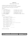
The example in Annexure B adds 10 clusters each of 4 096, 8 192, 16 384, 32 768 and 65 536 bytes to the
Network Stack Memory Pool. This translates to an additional 1,21 MB of system memory being allocated to the
Network Stack Memory Pool. Depending on the availability of free memory resources, the number of clusters
added can be adjusted. A new VxWorks target image has to be built for these changes to take effect.
4.1.2
Procedure for VxWorks 5.5 (if building target images using the command line)
If you are using the command line to build your VxWorks target images, the relevant file to edit will be
{tornado}/target/src/config/usrNetwork.c (not usrNetLib.c). The basic procedure and changes though are roughly
the same as those indicated in Annexure B. A new VxWorks target image has to be built for these changes to
take effect.
4.1.3
Procedure for VxWorks 6.x (if building target images using the Workbench IDE)
The Network Stack Memory Configuration can be reconfigured in the Workbench IDE for your VxWorks 6.x
target images. Under the Project Navigator tab, double click on Kernel Configuration for the current VxWorks
image project. In the Component configuration window, expand and select the "Network Components >
Network Core Components > Network Stack Memory Pool Configuration" branch and change the relevant
Property Values to include additional (larger than 2 048 bytes) clusters. A new VxWorks target image has to
be built for these changes to take effect.
4.2
To Build the Gigabit Ethernet VxWorks Software Driver into the VxWorks Kernel
Assume the BSP directory is given as : BSP_DIR = /tornado/target/config/dy4181.
4.3
!
Copy ccGeEnd18x.a to your $(BSP_DIR)/lib directory as ccGeEnd.a.
!
In the Builds section of the Project Workspace, change the Kernel properties to include the ccGeEnd.a
library file in the Macros LIBs option.
!
Rebuild all VxWorks images.
To Load the Software Driver Separately
Note :
This step is not required if the software driver was built into the BSP.
If the software driver is not built into the BSP, a user can load it separately :
!
Copy ccGeEnd18x.a to your present working directory as ccGeEnd.a.
!
From the VxWorks shell, type :
•
ld < ccGeEnd.a
CCII/GE/6-MAN/002
CGEMAN02.WPD
2009-08-20
Issue 1.1
Page 4 of 12
5.
Using the Gigabit Ethernet Software Driver
5.1
DualNet and RLMT Modes
The two ports of the GE Adapter may be used either to provide two independent communication channels
(DualNet mode) or as a single dual redundant channel (RLMT mode).
In DualNet mode, each channel is assigned is own IP address.
In RLMT mode, the secondary port becomes a “hot standby” in the event of failure of the primary port. Only one
IP address is assigned as the hardware will determine over which physical channel the data is routed.
5.2
Loading and Starting the Driver in DualNet Mode
To start the driver in DualNet mode :
muxDevStart(muxDevLoad(0,geLoad,"",0,0))
muxDevStart(muxDevLoad(1,geLoad,"",0,0))
This will create two devices, “ccge0" and “ccge1".
5.3
Loading and Starting the Driver in RLMT Mode
To start the driver in RLMT mode :
muxDevStart(muxDevLoad(0,geLoad,"RlmtMode=CheckLinkState",0,0))
5.4
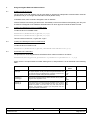
Command Line Parameters
The general form of the Gigabit Ethernet Software Driver loads command is as follows :
muxDevLoad(device,geLoad,"parameter-1:parameter-2:parameter-3...",0,0)
where device is a unique instance number starting from 0, and parameter-n is as described in the following
table :
Parameter
Description
Permitted
Values
Default Value
Speed_A
Speed_B
This parameter is used to set the speed capabilities. It is only valid
for copper adapters. Usually, the speed is negotiated between the
two channels during link establishment. If this fails, a channel can
be forced to a specific setting with this parameter.
10
100
1 000
Auto
Auto
AutoNeg_A
AutoNeg_B
The "Sense"-mode automatically detects whether the link partner
supports auto-negotiation or not.
On
Off
Sense
On
DupCap_A
DupCap_B
This parameters is only relevant if auto-negotiation for this channel
is not set to "Sense". If auto-negotiation is set to "On", all three
values are possible. If it is set to "Off", only "Full" and "Half" are
allowed. This parameter is useful if your link partner does not
support all possible combinations.
Half
Full
Both
Both
CCII/GE/6-MAN/002
CGEMAN02.WPD
2009-08-20
Issue 1.1
Page 5 of 12
Parameter
FlowCtrl_A
FlowCtrl_B
Description
Permitted
Values
This parameter can be used to set the flow control capabilities the
channel reports during auto-negotiation. It can be set for each
channel individually.
•
Sym
•
SymOrRem = SymmetricOrRemote : both or only remote
partner are allowed to send PAUSE frames.
•
LocSend
= LocalSend : only local link partner is allowed to
send PAUSE frames.
•
None
= Mo link partner is allowed to send PAUSE
frames.
Default Value
Sym
SymOrRem
LocSend
None
SymOrRem
= Symmetric : both link partners are allowed to
send PAUSE frames.
Role_A
Role_B
This parameter is only valid for the copper adapters. For two
1 000 Base-T adapters to communicate, one must take the role of
the master (providing timing information), while the other must be
the slave. Usually, this is negotiated between the two adapters
during link establishment. If this fails, an adapter can be forced to
a specific setting with this parameter.
Auto
Master
Slave
Auto
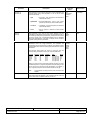
ConType
The parameter 'ConType' is a combination of all five per-channel
parameters within one single parameter. This simplifies the
configuration of both channels of an adapter. The different values
of this variable reflect the most meaningful combinations of channel
parameters.
Auto
1000FD
100FD
100HD
10FD
10HD
Auto
A
B
A
The following table shows the values of 'ConType' and the
corresponding combinations of the per-channel parameters :
ConType
Auto
1000FD
100FD
100HD
10FD
10HD
DupCap
Both
Full
Full
Half
Full
Half
AutoNeg
On
Off
Off
Off
Off
Off
FlowCtrl
SymOrRem
None
None
None
None
None
Role
Auto Auto
Auto (ignored)
Auto (ignored)
Auto (ignored)
Auto (ignored)
Auto (ignored)
Speed
1000
100
100
10
10
Stating any other channel parameter together with this 'ConType'
variable will result in a merged configuration of those settings. This
due to the fact, that the per-channel parameters (e.g. Speed_?)
have a higher priority than the combined variable 'ConType'.
Note :
PrefPort
CCII/GE/6-MAN/002
CGEMAN02.WPD
This parameter is always used on both channels of the
adapter.
This is used to force the preferred channel to A or B (on
dual-channel network adapters). The preferred channel is the one
that is used if both are detected as fully functional.
2009-08-20
Issue 1.1
Page 6 of 12
Parameter
RlmtMode
Description
Permitted
Values
RLMT monitors the status of the channel. If the link of the active
channel fails, RLMT switches immediately to the standby link. The
virtual link is maintained as long as at least one 'physical' link is up.
CheckLinkState
CheckLocalPort
CheckSeg
DualNet
DualNet
30 ... 40 000
(interrupts per
second)
2 000
• CheckLinkState
Default Value
- Check link state only : RLMT uses the link
state reported by the adapter hardware for
each individual channel to determine
whether a channel can be used for all
network traffic or not.
• CheckLocalPort - In this mode, RLMT monitors the network
path between the two channels of an
adapter by regularly exchanging packets
between them. This mode requires a
network configuration in which the two
channels are able to "see" each other (i.e.
there must not be any router between the
channels).
• CheckSeg
- Check local channel and segmentation :
This mode supports the same functions
as the CheckLocalPort mode and
additionally checks network segmentation
between the channels. Therefore, this
mode is only to be used if Gigabit
Ethernet switches are installed on the
network that have been configured to use
the Spanning Tree protocol.
• DualNet
- In this mode, channels A and B are used
as separate devices. If you have a dual
channel adapter, channel A will be
configured as eth0 and channel B as
eth1. Both channels can be used
independently with distinct IP addresses.
The preferred channel setting is not used.
RLMT is turned off.
Note :
IntsPerSec
RLMT modes CLP and CLPSS are designed to operate
in configurations where a network path between the
channels on one adapter exists. Moreover, they are not
designed to work where adapters are connected
back-to-back.
This parameter is only used, if either static or dynamic interrupt
moderation is used on a network adapter. Using this parameter if
no moderation is applied, will lead to no action performed.
This parameter determines the length of any interrupt moderation
interval. Assuming that static interrupt moderation is to be used, an
'IntsPerSec' parameter value of 2 000 will lead to an interrupt
moderation interval of 500 microseconds.
Note :
CCII/GE/6-MAN/002
CGEMAN02.WPD
The duration of the moderation interval is to be chosen
with care. At first glance, selecting a very long duration
(e.g. only 100 interrupts per second) seems to be
meaningful, but the increase of packet-processing delay
is tremendous. On the other hand, selecting a very short
moderation time might compensate the use of any
moderation being applied.
2009-08-20
Issue 1.1
Page 7 of 12
Parameter
Moderation
Description
Interrupt moderation is employed to limit the maximum number of
interrupts the driver has to serve. That is, one or more interrupts
(which indicate any transmit or receive packet to be processed) are
queued until the driver processes them. When queued interrupts
are to be served, is determined by the 'IntsPerSec' parameter,
which is explained later below.
• None
-
No interrupt moderation is applied on the adapter.
Therefore, each transmit or receive interrupt is
served immediately as soon as it appears on the
interrupt line of the adapter.
• Static
-
Interrupt moderation is applied on the adapter. All
transmit and receive interrupts are queued until a
complete moderation interval ends. If such a
moderation interval ends, all queued interrupts
are processed in one big bunch without any
delay. The term 'static' reflects the fact, that
interrupt moderation is always enabled,
regardless how much network load is currently
passing via a particular interface. In addition, the
duration of the moderation interval has a fixed
length that never changes while the driver is
operational.
• Dynamic -
Interrupt moderation might be applied on the
adapter, depending on the load of the system. If
the driver detects that the system load is too
high, the driver tries to shield the system against
too much network load by enabling interrupt
moderation. If - at a later time - the CPU
utilisation decreases again (or if the network load
is negligible) the interrupt moderation will
automatically be disabled.
Permitted
Values
Default Value
None
Static
Dynamic
Dynamic
On
Off
Off
On
Off
Off
Interrupt moderation should be used when the driver has to handle
one or more interfaces with a high network load, which - as a
consequence - leads also to a high CPU utilisation. When
moderation is applied in such high network load situations, CPU
load might be reduced by 20-30%.
Note :
LowLatency
The drawback of using interrupt moderation is an
increase of the round-trip-time (RTT), due to the
queueing and serving of interrupts at dedicated
moderation times.
This is used to reduce the packet latency time of the adapter.
Setting the LowLatency parameter to 'On' forces the adapter to
pass any received packet immediately to upper network layers and
to send out any transmit packet as fast as possible.
Note 1 :
The system load increases if LowLatency is set to 'On'
and a lot of data packets are transmitted and received.
Note 2 :
This parameter is only used on adapters which are
based on PCI Express compatible chipsets.
BroadcastPrio
This parameter specifies whether received broadcast packets have
the highest priority for the channel switch decision ("Off") or not
("On").
RlmtMinToVal
Minimum timeout value for RLMT (in :s)
30 000
RlmtDefToVal
Minimum timeout value for RLMT (in :s)
30 000
RlmtPortdownTimVal
RLMT Port Down Timer (in :s)
90 000
RlmtPortstartTimVal
RLMT Port Start Timer (in :s)
50 000
RlmtPortupTimVal
RLMT Port Up Timer (in :s)
2 500 000
CCII/GE/6-MAN/002
CGEMAN02.WPD
2009-08-20
Issue 1.1
Page 8 of 12
Parameter
RlmtSegToVal
Note :
RLMT Network Segmentation Reporting Interval (in :s)
Permitted
Values
Default Value
900 000 000
If DualNet mode is used, the parameters for both channels must be provided in the first call to
muxDevLoad. Parameters provided in the second call will be ignored.
CCII/GE/6-MAN/002
CGEMAN02.WPD
Description
2009-08-20
Issue 1.1
Page 9 of 12
6.
Contact Details
6.1
Contact Person
Direct all correspondence and / or support queries to the Project Manager (Board Level Products) at
C²I² Systems.
6.2
Physical Address
C²I² Systems
Unit 3, Rosmead Place, Rosmead Centre
67 Rosmead Avenue
Kenilworth
Cape Town
7708
South Africa
6.3
Postal Address
C²I² Systems
P.O. Box 171
Rondebosch
7701
South Africa
6.4
Voice and Electronic Contacts
Tel :
Fax :
Email :
Email :
URL :
6.5
(+27) (0)21 683 5490
(+27) (0)21 683 5435
[email protected]
[email protected]
http://www.ccii.co.za/
Product Support
Support on C²I² Systems products is available telephonically between Monday and Friday from 09:00 to
17:00 CAT. Central African Time (CAT = GMT + 2).
Email support is available at [email protected]
CCII/GE/6-MAN/002
CGEMAN02.WPD
2009-08-20
Issue 1.1
Page 10 of 12
Annexure A
Making Changes to sysNet.c for X86
On X86 platforms, the following amendment must be made to the BSP :
Copy the file sysCcGeEnd.c to your BSP configuration directory (target/config/BSPName).
Make the following two amendments to the file sysNet.c in the same directory :
Amendment 1 :
#ifdef INCLUDE_END
#
include "sysDec21x40End.c"
#
include "sysEl3c90xEnd.c"
#
include "sysElt3c509End.c"
#
include "sysFei82557End.c"
#
include "sysGei82543End.c"
#
include "sysLn97xEnd.c"
#
include "sysNe2000End.c"
#
include "sysUltraEnd.c"
#
include "sysCcGeEnd.c"
#endif /* INCLUDE_END */
/*
/*
/*
/*
/*
/*
/*
/*
/*
dec21x40End support routines */
el3c90xEnd support routines */
elt3c509End support routines */
fei82557End support routines */
gei82543End support routines */
ln97xEnd support routines
*/
ne2000End support routines
*/
ultraEnd support routines
*/
CCII GE END driver support routines */
Amendment 2 :
LOCAL VEND_ID_DESC vendorIdEnet [] =
{
#if defined(INCLUDE_DEC21X40_END)
{DEC_PCI_VENDOR_ID,
sysDec21x40PciInit},
#endif /* INCLUDE_DEC21X40_END */
#if defined(INCLUDE_LN_97X_END)
{AMD_PCI_VENDOR_ID,
sysLan97xPciInit},
#endif /* INCLUDE_LN_97X_END */
#if defined(INCLUDE_EL_3C90X_END)
{THREECOM_PCI_VENDOR_ID, sysEl3c90xPciInit},
#endif /* INCLUDE_EL_3C90X_END */
#if defined(INCLUDE_GEI8254X_END) || defined(INCLUDE_GEI_HEND)
{INTEL_PCI_VENDOR_ID,
sys543PciInit},
#endif /* INCLUDE_GEI8254X_END */
#if defined(INCLUDE_FEI_END)
{INTEL_PCI_VENDOR_ID,
sys557PciInit},
#endif /* INCLUDE_FEI_END */
{0x1148, sysCcGePciInit},
{0xffffffff, NULL}
};
/* last entry */
Now remake your VxWorks image.
CCII/GE/6-MAN/002
CGEMAN02.WPD
2009-08-20
Issue 1.1
Page 11 of 12
Annexure B
Making Changes to usrNetLib.c for Large UDP Packets
/* OVS: Added these lines to add larger Network Data Pool clusters to the VxWorks image
*/
/* C²I² Systems: To restore file to original config, simply delete all lines marked
"C²I² Systems" */
/* C²I² Systems */ #undef NUM_CL_BLKS
/* C²I² Systems */ #define NUM_CL_BLKS (NUM_64 + NUM_128 + NUM_256 + NUM_512 + NUM_1024
+ NUM_2048 + NUM_4096 + NUM_8192 + NUM_16384 + NUM_32768 + NUM_65536)
/* C²I² Systems */ #undef NUM_64
/* C²I² Systems */ #define NUM_64 100
/* C²I² Systems */ #undef NUM_128
/* C²I² Systems */ #define NUM_128 100
/* C²I² Systems */ #undef NUM_256
/* C²I² Systems */ #define NUM_256 40
/* C²I² Systems */ #undef NUM_512
/* C²I² Systems */ #define NUM_512 40
/* C²I² Systems */ #undef NUM_1024
/* C²I² Systems */ #define NUM_1024 25
/* C²I² Systems */ #undef NUM_2048
/* C²I² Systems */ #define NUM_2048 25
/* C²I² Systems */ #define NUM_4096 10
/* C²I² Systems */ #define NUM_8192 10
/* C²I² Systems */ #define NUM_16384 10
/* C²I² Systems */ #define NUM_32768 10
/* C²I² Systems */ #define NUM_65536 10
/*
/*
C²I² Systems */
C²I² Systems */
#undef NUM_NET_MBLKS
#define NUM_NET_MBLKS (2* NUM_CL_BLKS)
CL_DESC clDescTbl [] =
{
/*
clusterSize
----------*/
{64,
{128,
{256,
{512,
{1024,
{2048,
/* C²I² Systems */
/* C²I² Systems */
/* C²I² Systems */
/* C²I² Systems */
/* C²I² Systems */
};
CCII/GE/6-MAN/002
CGEMAN02.WPD
num
----
memArea
-------
memSize
-------
NUM_64,
NUM_128,
NUM_256,
NUM_512,
NUM_1024,
NUM_2048,
{4096,
{8192,
{16384,
{32768,
{65536,
NULL,
NULL,
NULL,
NULL,
NULL,
NULL,
NUM_4096,
NUM_8192,
NUM_16384,
NUM_32768,
NUM_65536,
0},
0},
0},
0},
0},
0},
NULL,
NULL,
NULL,
NULL,
NULL,
2009-08-20
0},
0},
0},
0},
0}
Issue 1.1
Page 12 of 12