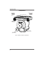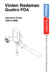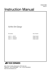
1
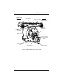
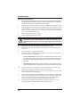
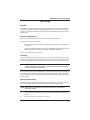
120EX Fluid Pan & Tilt Head
C1225-0001
M
N: .CO
IO N
AT OCO
TR N.
IS IO
EG AT
R R
T
NE IS
LI EG
N
O /R
:/
TP
T
H
Operators Guide
C1225-4980/2
OConnor 120EX
Fluid Pan & Tilt Head
Operators Guide
Publication Part No. C1225-4980 Issue 2
Copyright © Vitec Group plc 2010
All rights reserved throughout the world. No part of this
document may be stored in a retrieval system, transmitted,
copied or reproduced in any way including, but not limited to,
photocopy, photograph, magnetic or other record without the
prior agreement and permission in writing of Vitec Group plc.
Trademarks
OConnor® is a registered trademark of the Vitec Group plc.
Important information about this document
Information contained within this document is subject to
change. Camera Dynamics Limited reserves the right, without
notice to make changes in equipment design or performance
as progress in engineering, manufacturing or technology may
warrant.
Published by
Camera Dynamics Ltd
Technical Publications Department
William Vinten Building
Western Way
Bury St Edmunds
Suffolk IP33 3TB
UK
Email: [email protected]
120EX Fluid Pan & Tilt Head
Preface
Thank you and congratulations on the purchase your new 120EX from OConnor.
We want you to get the most from your new 120EX, and therefore encourage you to read this
operator's guide to familiarize yourself with its many features, some of which may be new to you.
It also covers essential health and safety information and a section on maintenance that will
ensure you keep your new product in perfect condition.
Features and benefits of your new 120EX
The 120EX head is the flagship of OConnor's new EXTENDED CAPACITY range of fluid heads
- the EX range. Based on the new patented EX-technology, this head features a new kind of
stepless counterbalance system as well as a new ultra-smooth pan and tilt fluid drag designed
for film style shooting.
OConnor's fluid heads are famous for ultimate control and stability for film style shooting. Now,
with the use of EX-technology, OConnor can offer the features it has become famous for with
the additional benefit of extended capacity. With a new counterbalance mechanism at the heart
of the EX-technology, the 120EX can be boosted into EX-mode to achieve a whole new realm
of counterbalance. True and accurate balance is achieved through the sinusoidal EXcounterbalance technology. The EX-drag technology is ultra-smooth and stepless - just what
OConnor is famous for.
The EX-Mode
Getting more than 100% is the best way to describe the EX-Mode on the new EX range of fluid
heads by OConnor. The EX fluid heads have a given payload range for the ±90° tilt range. With
traditional counterbalance mechanisms any payload heavier than this maximum weight cannot
be balanced. But with the EX range of fluid heads, you can go far beyond that maximum payload
by slowly limiting the tilt range as the payload is increased. The tilt range is still an impressive
±60° at the maximum payload of 240 lbs (109 kg). The full tilt range of ±90° is maintained with
payloads between 30-120 lbs (14-54 kg). All of these ranges are based on an 8" center of
gravity.
Other Features
A collapsible counterbalance crank knob and digital readout make counterbalancing the payload
easy - even though the range is huge. The new easy-to-use sideload mechanism features a
push and turn platform knob with a "pop up" gear to engage the camera mounting plate and
adjust the platform fore and aft easily and precisely. It is easy to move heavy camera payloads
forward and backwards on the head with this mechanism. Geared and non-geared plates can
be used on the platform.
OConnor's fluid drag system allows an extremely quick pan movement from one position to
another, recovering instantly without any spring back. You can set up easily in low light
conditions using the illuminated level bubble and back-lit display.
Once again, thank you for choosing the 120EX. We are confident it will give you many years of
reliable performance.
3
Operators Guide
Safety - read this first
Warning Symbols in this Operators Guide
Where there is a risk of personal injury or injury to others, comments appear
highlighted by the word WARNING!—supported by the warning triangle symbol.
Where there is a risk of damage to the product, associated equipment, process or
surroundings, comments appear highlighted by the word CAUTION!
Disposal of waste batteries
Any batteries included with this product must not be treated as household waste. By ensuring
these batteries are disposed of correctly, you will help prevent potentially negative
consequences for the environment and human health, and help conserve natural resources.
Read ‘Battery Replacement’ section in this manual for instructions on how to remove the
battery from the product safely. Hand the battery over to the applicable collection point for
recycling waste batteries.
Further Information
For further information or advice regarding this pan and tilt head, please contact OConnor
Engineering at:
OCONNOR ENGINEERING
2701 N. Ontario St.
Burbank, CA 91504
USA
Tel: +1 818 847 8666
Fax: +1 818 847 1205
E-mail: [email protected]
Or visit our website www.ocon.com and use the contact form.
4
120EX Fluid Pan & Tilt Head
Technical specification
Note: Payload capacity and tilt ranges are based on a C of G height of 8" (20.3 cm).
Payload Capacity:. . . . . . . . . . . . . . . . . . . . . . . . . . . . . . . . . . . . . . . . . .30 - 240 lb (14 - 109 kg)
. . . . . . . . . . . . . . . . . . . . . . . . . . . . . . . . . . . . . . . . . . . . . . . . . . . . . . See counterbalance chart
Tilt Range . . . . . . . . . . . . . . . . . . . . . . . . . . . . . . . . . . . . . ±90° for payloads up to 120 lb (54 kg)
. . . . . . . . . . . . . . . . . . . . . . . . . . . . . . . . . . . . . . . . . . . . . ±80° for payloads up to 147 lb (67 kg)
. . . . . . . . . . . . . . . . . . . . . . . . . . . . . . . . . . . . . . . . . . . . . ±70° for payloads up to 188 lb (85 kg)
. . . . . . . . . . . . . . . . . . . . . . . . . . . . . . . . . . . . . . . . . . . . ±60° for payloads up to 240 lb (109 kg)
Pan Range . . . . . . . . . . . . . . . . . . . . . . . . . . . . . . . . . . . . . . . . . . . . . . . . . . . . . . . . . . . . . . 360°
Height: . . . . . . . . . . . . . . . . . . . . . . . . . . . . . . . . . . . . . . . . . . . . . . . . . . . . . . . . 9.8 in (24.8 cm)
Width: . . . . . . . . . . . . . . . . . . . . . . . . . . . . . . . . . . . . . . . . . . . . . . . . . . . . . . . . 13.2 in (34.1 cm)
Depth:. . . . . . . . . . . . . . . . . . . . . . . . . . . . . . . . . . . . . . . . . . . . . . . . . . . . . . . . 10.4 in (26.5 cm)
Weight: . . . . . . . . . . . . . . . . . . . . . . . . . . . . . . . . . . . . . . . . . . . . . . . . . . . . . . . . 34 lb (15.5 kg)
Operating Temperature Range . . . . . . . . . . . . . . . . . . . . . . . -40°F to +140°F (-40°C to +60°C)
Dolly/tripod fixing . . . . . . . . . . . . . . . . . . . . . . . . . . . . . . . . . . . . . . . . . . . . . . . . . . Mitchell base
5
Operators Guide
6
120EX Fluid Pan & Tilt Head
Contents
Page
Preface . . . . . . . . . . . . . . . . . . . . . . . . . . . . . . . . . . . . . . . . . . . . . . . . . . . . . . . . . 3
Safety - read this first. . . . . . . . . . . . . . . . . . . . . . . . . . . . . . . . . . . . . . . . . . . . . . 4
Disposal of waste batteries . . . . . . . . . . . . . . . . . . . . . . . . . . . . . . . . . . . . . . . . . 4
Technical specification . . . . . . . . . . . . . . . . . . . . . . . . . . . . . . . . . . . . . . . . . . . . 5
Further Information . . . . . . . . . . . . . . . . . . . . . . . . . . . . . . . . . . . . . . . . . . . . . . . 4
Components . . . . . . . . . . . . . . . . . . . . . . . . . . . . . . . . . . . . . . . . . . . . . . . . . . . . . 8
Introduction . . . . . . . . . . . . . . . . . . . . . . . . . . . . . . . . . . . . . . . . . . . . . . . . . . . . 10
Extended capacity balance . . . . . . . . . . . . . . . . . . . . . . . . . . . . . . . . . . . . . . . . . . . . . . 10
Digital display . . . . . . . . . . . . . . . . . . . . . . . . . . . . . . . . . . . . . . . . . . . . . . . . . . . . . . . . . 10
Ultra smooth fluid drag. . . . . . . . . . . . . . . . . . . . . . . . . . . . . . . . . . . . . . . . . . . . . . . . . . 11
Pan and tilt locks . . . . . . . . . . . . . . . . . . . . . . . . . . . . . . . . . . . . . . . . . . . . . . . . . . . . . . 11
Tilt lock pin . . . . . . . . . . . . . . . . . . . . . . . . . . . . . . . . . . . . . . . . . . . . . . . . . . . . . . . . . . . 11
Illuminated bubble level . . . . . . . . . . . . . . . . . . . . . . . . . . . . . . . . . . . . . . . . . . . . . . . . . 11
Handle mounting . . . . . . . . . . . . . . . . . . . . . . . . . . . . . . . . . . . . . . . . . . . . . . . . . . . . . . 11
Camera mounting platform . . . . . . . . . . . . . . . . . . . . . . . . . . . . . . . . . . . . . . . . . . . . . . 11
Mitchell mount . . . . . . . . . . . . . . . . . . . . . . . . . . . . . . . . . . . . . . . . . . . . . . . . . . . . . . . . 11
Operation . . . . . . . . . . . . . . . . . . . . . . . . . . . . . . . . . . . . . . . . . . . . . . . . . . . . . . 12
Installing the head . . . . . . . . . . . . . . . . . . . . . . . . . . . . . . . . . . . . . . . . . . . . . . . . . . . . . 12
Handles . . . . . . . . . . . . . . . . . . . . . . . . . . . . . . . . . . . . . . . . . . . . . . . . . . . . . . . . . . . . . 12
Eyepiece leveller . . . . . . . . . . . . . . . . . . . . . . . . . . . . . . . . . . . . . . . . . . . . . . . . . . . . . . 12
Mounting a camera . . . . . . . . . . . . . . . . . . . . . . . . . . . . . . . . . . . . . . . . . . . . . . . . . . . . 12
Stability. . . . . . . . . . . . . . . . . . . . . . . . . . . . . . . . . . . . . . . . . . . . . . . . . . . . . . . . . . . . . . 13
Balancing the head . . . . . . . . . . . . . . . . . . . . . . . . . . . . . . . . . . . . . . . . . . . . . . . . . . . . 13
Balancing the head . . . . . . . . . . . . . . . . . . . . . . . . . . . . . . . . . . . . . . . . . . . . . . . . . 14
Payload weight and C of G height adjustment. . . . . . . . . . . . . . . . . . . . . . . . . . . . . . . . 15
Locking the platform. . . . . . . . . . . . . . . . . . . . . . . . . . . . . . . . . . . . . . . . . . . . . . . . . . . . 15
Pan and tilt locks . . . . . . . . . . . . . . . . . . . . . . . . . . . . . . . . . . . . . . . . . . . . . . . . . . . . . . 15
Pan and tilt fluid drag . . . . . . . . . . . . . . . . . . . . . . . . . . . . . . . . . . . . . . . . . . . . . . . . . . . 16
Balance display . . . . . . . . . . . . . . . . . . . . . . . . . . . . . . . . . . . . . . . . . . . . . . . . . . . . . . . 16
Low battery . . . . . . . . . . . . . . . . . . . . . . . . . . . . . . . . . . . . . . . . . . . . . . . . . . . . . . . 16
Servicing . . . . . . . . . . . . . . . . . . . . . . . . . . . . . . . . . . . . . . . . . . . . . . . . . . . . . . . 17
General . . . . . . . . . . . . . . . . . . . . . . . . . . . . . . . . . . . . . . . . . . . . . . . . . . . . . . . . . . . . . 17
Routine maintenance . . . . . . . . . . . . . . . . . . . . . . . . . . . . . . . . . . . . . . . . . . . . . . . . . . . 17
Cleaning. . . . . . . . . . . . . . . . . . . . . . . . . . . . . . . . . . . . . . . . . . . . . . . . . . . . . . . . . . . . . 17
Battery replacement. . . . . . . . . . . . . . . . . . . . . . . . . . . . . . . . . . . . . . . . . . . . . . . . . . . . 17
Balance mechanism calibration . . . . . . . . . . . . . . . . . . . . . . . . . . . . . . . . . . . . . . . . . . . 18
Adjusting the lock levers . . . . . . . . . . . . . . . . . . . . . . . . . . . . . . . . . . . . . . . . . . . . . . . . 19
7
Operators Guide
Components
CAMERA LENS
OPERATOR
Camera Plate Mounting
Serial No.
Handle/accessory
mountings
Tilt fluid drag
adjustment knob
Pan fluid drag
adjustment knob
Figure 1 120EX Pan & Tilt Head - right-hand-side
8
120EX Fluid Pan & Tilt Head
CAMERA LENS
Safety latch
OPERATOR
Platform plate
hook release
Platform adjustment
knob
Platform release
lever
Battery
compartment
Handle/accessory
mountings
Display actuator
Tilt lock pin
Digital display
Tilt lock lever
Mounting point for
optional undermount
eyepiece leveller
(EPL)
Illuminated bubble
level
Pan lock lever
Counter balance
adjustment crank
Figure 2 120EX Pan & Tilt Head - left-hand-side
9
Operators Guide
Introduction
The 120EX pan and tilt head embodies a unique and patented EX-counterbalance mechanism
for true and accurate balance, EX-drag assemblies for ultra-smooth pan and tilt motions and an
adjustable camera mounting plate.
Extended capacity balance
The spring counterbalancing mechanism comprises four springs operating against a threedimensional cam connected to the camera mounting platform. The balance mechanism is
adjusted by the counterbalance crank on the lower left rear of the head. The knob has a
retractable handle and the 'push in and turn' action uses a clutch to prevent inadvertent damage
to the balance mechanism. Adjustments should only be made with the platform in the horizontal
position.
Maximum and minimum payloads that can be balanced, and tilt ranges, are dependent on the
weight of the camera and accessories and on the center of gravity (C of G) height. The graph
below shows the range of loads and C of G heights that can be maintained in balance. At the
lower end of the weight range the full ±90 degree tilt range is available while at the maximum
load the tilt range is reduced to ±60 degrees.
Figure 3 120EX Pan & Tilt Head - balance graph
Digital display
The digital display indicates the setting of the balance mechanism on a scale of 0-182%. Press
the display actuator button to illuminate the display and adjust the counterbalance crank. At
settings above 100% the EX indicator will turn on to alert you to the reduced tilt range. The
display turns off automatically approximately 15 seconds after you stop adjusting. The display
dims in dark surroundings.
10
120EX Fluid Pan & Tilt Head
Ultra smooth fluid drag
Both the pan and tilt mechanisms incorporate OConnor's ultra smooth fluid drag to ensure
smooth movement. The pan and tilt drag adjustment knobs are on the right side of the head and
are continuously adjustable from 0 to 9.
Pan and tilt locks
Friction locks on each axis allow the head to be locked at any desired position. The pan and tilt
lock levers are on the left-side of the head.
Tilt lock pin
The tilt lock pin on the left side of the head is used to lock the head in a horizontal position. The
lock pin is actuated by a flip lever with red (locked) and green (unlocked) label indicators.
Illuminated bubble level
The bubble level on the left side of the head can be illuminated by pressing the display actuator
button. The light will go out after approximately 15 seconds.
Handle mounting
Handle mounting points are located at the front and rear of the head, on both the left and right
sides. A telescoping extension handle is supplied and is attached using the handle clamp, with
angular adjustment available on the rosette serrations. Additional handles, including a front
handle and accessories can also be installed.
Camera mounting platform
The camera is attached to the head by means of an OConnor geared plate, an OConnor plate,
a 120 mm Euro plate, a Panavision dovetail plate or an Arriflex dovetail plate. The platform will
accept geared or non-geared plates.
Mitchell mount
The 120EX head is provided with a standard Mitchell base mount.
11
Operators Guide
Operation
Installing the head
The 120EX head may be installed on a standard tripod with a Mitchell base mount using the
tiedown knob assembly provided. After securely mounting the head on the tripod, use the bubble
level to set it level. If necessary, press the display actuator to illuminate the bubble level.
Handles
Install the handles on the rosette handle mounts and adjust the position before tightening the
clamps. Adjust the length of the telescoping handle as desired.
Eyepiece leveller
If required, install the optional undermount eyepiece leveler (EPL) assembly on the left hand side
below the counterbalance crank. The eyepiece leveler is compatible with Arri's eyepiece rods.
Alternatively, the rear mount eyepiece leveler is attached to the left rear shoulder screws.
Mounting a camera
Warning!
Do not rely on the tilt lock when changing the payload. Always tilt the
platform horizontal and engage the tilt lock pin by placing it in the red
(engaged) position. The tilt pin will drop into the platform.
NOTE: Ensure that the weight and C of G height of the total payload is within the
range of which the head is designed.
If you are installing the head on a pedestal or dolly, lock the pedestal or dolly
BEFORE mounting the camera.
To mount the camera:
1.
Attach the mounting plate to the bottom of the camera/lens.
2.
Engage the tilt lock pin.
3.
Release the safety latch and pull out the platform release lever.
4.
Press down and hold the platform hook release (red tang) on the left hand side of the
head.
5.
Position the camera and mounting plate on top of the head and release the hook to
secure the mounting plate.
6.
Engage the platform release lever by rotating it towards the platform.
7.
Install the remainder of the payload (lens, zoom and focus controls, viewfinder, prompter
etc.).
12
120EX Fluid Pan & Tilt Head
Stability
Warning!
When mounting the head on a tripod, it is possible to set the tripod legs so
that the center of gravity of the tilted payload falls outside the footprint of the
tripod, leading to instability.
Use the mid-level or floor spreader to ensure that the tripod legs are spread sufficiently so that
the center of gravity of the tilted payload remains within the footprint of the tripod.
Balancing the head
Make sure that the head is level before balancing. Check the bubble level to verify that the head
itself is level and make sure that the platform is also level.
NOTE: It is important that the handle(s) and all camera accessories (lens, zoom and
focus controls, viewfinder, prompter etc.) are fitted in their operational position
before balancing the head. Any equipment fitted or adjusted later can
unbalance the head.
Balancing the 120EX head achieves two objectives. First, when a head is correctly balanced the
operator will need a minimum amount of effort to move the head. Second, once balanced, the
head and its payload can be set to any tilt position and the head will maintain this position with
'hands off'.
The chart below shows the range of load and C of G heights that can be maintained in balance.
The area between the min. and 90° lines (shaded white) corresponds to load/C of G
combinations that can be balanced over the full tilt range of ±90°. The area to the right of the 90°
line (shaded grey) corresponds to the progressively reducing tilt range with greater load and
higher C of G combinations.
Figure 4 120EX Pan & Tilt Head - balance graph
13
Operators Guide
Setting fore and aft balance
1.
When positioning the payload, it is important to be aware of the potential danger that an
unbalanced payload will fall away suddenly. Always be prepared for this by maintaining
a firm hold on the payload until the balance is set correctly.
2.
Make sure that the camera and all accessories are installed in their operating positions.
3.
Before disengaging the tilt lock pin, press the Display actuator button and press and turn
the Counterbalance crank to set the counterbalance to 50%. Depending on the payload
weight, it may be necessary to increase or decrease this setting to enable the payload
to be correctly balanced fore and aft.
4.
Make sure that the tilt lock pin is engaged.
5.
Set the tilt fluid drag adjustment knob to 0.
Warning!
Be prepared to prevent the head falling away suddenly. In the event of the
head falling away suddenly, increase the setting on the balance adjustment
knob.
6.
Holding the handle to steady the platform, disengage the tilt lock pin.
7.
Tilt the platform forwards and backwards and determine if camera package is front or
back heavy.
8.
If it is not in balance, re-engage the tilt lock pin.
9.
Release the safety latch and disengage the platform release lever. The next step will
depend on the type of mounting plate:
•
OConnor Geared Plate: Press in and turn the platform adjustment knob to move
the geared plate forwards or backwards until the payload is balanced fore and aft.
The "pop up" gear will engage the plate gear rack. Pull out the knob if needed to
disengage.
•
Other Mounting Plates: With the help of an assistant, carefully slide the camera
payload and plate forwards or backwards until the payload is balanced fore and aft.
10.
The horizontal balance is correct when no perceptible tilting force can be felt on the
handle with the platform level and with the tilt lock pin disengaged.
11.
Fully engage the platform release lever to secure the payload in position. The red safety
button should engage the platform hook.
12.
If there is insufficient movement in the sliding plate to achieve balance, determine which
direction the mounting plate needs to be moved to achieve correct balance. Remove the
payload from the head, reattach the mounting plate to the camera in the required
position, remount the load and repeat the horizontal balancing procedure.
13.
The sliding plate is marked and the platform has graduations. Make a note of the
"balanced" position to simplify rebalancing this particular payload.
14
120EX Fluid Pan & Tilt Head
Payload weight and C of G height adjustment
The fore and aft balance must be set before adjusting the payload weight and C of G height
adjustment.
NOTE: If the correct digital balance setting of the payload is known, tilt the platform to
the horizontal position, press the display actuator button and push in and turn
the counterbalance crank until the digital display shows the correct setting.
1.
Using the handle, tilt the platform downwards and upwards. When correctly balanced,
there should be no perceptible tilting force on the handle at any angle of tilt and the head
should remain in any tilt position to which it is set.
2.
If the head tends to fall away when the platform is tilted, the Counterbalance will need
to be increased. If the head tends to spring back when the platform is tilted the
counterbalance will need to be decreased.
3.
Set the platform level, press the display actuator button and push in and turn the
counterbalance crank to increase or decrease the counterbalance setting as required.
4.
Using the handle, tilt the platform upward and downward to recheck the balance.
Readjust counterbalance until balance is achieved.
5.
Make a note of the final counterbalance setting to simplify rebalancing this particular
payload.
6.
When the payload weight and C of G height adjustment is complete, check that the fore
and aft balance is still correct. Re-adjust the position of the sliding plate if necessary.
7.
After balancing, exercise the head through the full range of pan and tilt to confirm that it
operates smoothly.
Locking the platform
The tilt lock pin mechanism is operated by a flip lever on the left-hand side of the head. To
engage the pin, hold the platform in the horizontal position and flip the lever over from the green
position to the red position. If necessary, use the handle to rock the head slightly to achieve the
fully locked position. The pin and flip lever will snap towards the platform as the pin engages.
To release the tilt lock pin, flip the lever over from the red position to the green position. If the
platform is not balanced this may require force. If so, make sure that the tilt lock lever is rotated
clockwise to hold the platform in place.
Pan and tilt locks
The pan and tilt friction locks are operated by levers on the left of the head. The locks should be
applied whenever the camera/head is left unattended.
Rotate the pan lock lever clockwise (toward the front of the head) to engage the lock.
Rotate the tilt lock lever counter clockwise (upwards) to engage the lock.
If the lock does not fully engage at the end of the lock lever travel, refer to "Adjusting The Lock
Levers" in the Servicing section of this manual.
15
Operators Guide
Pan and tilt fluid drag
Both the pan and tilt mechanisms incorporate the OConnor ultra smooth fluid drag system to
ensure smooth movement. Control knobs on the right side of the head are used to adjust the
drag settings over the range of 0 to 9. The pan drag knob is the smaller one at the base of the
head. The larger tilt drag knob is in the center on the tilt drag housing. To increase drag, turn the
knob clockwise, towards a higher setting. To decrease drag, turn the knob counter-clockwise,
towards a lower setting.
Balance display
The balance display is enabled by the display actuator button. It remains active for
approximately 15 seconds after adjustment of the counterbalance crank has finished.
Low battery
The balance display will flash when the battery requires replacement (see "Battery
Replacement" in the Servicing section).
16
120EX Fluid Pan & Tilt Head
Servicing
General
The 120EX pan and tilt head is robustly made to high engineering standards and little attention
is required to maintain serviceability except for regular cleaning. For service beyond regular
maintenance detailed in this manual, contact the OConnor headquarters or your local OConnor
representative.
Routine maintenance
Replace the electronic unit battery whenever the low battery indicator flashes.
During normal use, check the following:
Check the effectiveness of the pan and tilt locks. Reset as necessary - see Adjusting the
Lock Levers.
Check the operation of the balance mechanism digital display and the illumination of the
bubble level. Replace the battery if necessary - see Battery Replacement.
No other routine maintenance is required.
Cleaning
During normal operation the only cleaning required is a periodic wipe down with a lint-free cloth.
Any dirt that accumulates during storage or periods of non-use may be removed with a semi-stiff
brush. Particular attention should be paid to the dovetail faces of the camera mounting area.
NOTE: Use only detergent-based cleaners. DO NOT use solvent-based or oil-based
cleaners, abrasives or wire brushes to remove accumulations of dirt as these
will damage the protective surfaces.
Use out-of-doors under adverse conditions may require special attention and the head should
be covered when not in use. Salt spray should be washed off using fresh water at the earliest
opportunity. Sand and dirt act as an abrasive and should be removed using a semi-stiff brush or
a vacuum cleaner.
Battery replacement
The battery powers the digital display and illuminates the bubble level. It should be replaced
whenever the display flashes. The head requires a 9V PP3 battery (Lithium type).
NOTE: Replacement of the battery will not affect the calibration of the balance
mechanism display.
1.
Use a flat blade screwdriver to remove the three slotted screws in the battery cover
(Figure 5).
2.
Remove the battery cover and place to one side.
17
Operators Guide
3.
Carefully pull the battery out of its compartment as far as the wiring will allow.
4.
Pull the connector off the terminals of the old battery and push it onto the terminals of
the new battery. For longer battery life it is recommended that you use a 9 V lithium
battery. However, a standard 9 V battery can also be used.
5.
Replace the battery in its compartment, making sure that the wiring is not twisted or
pinched.
6.
Replace the battery cover and tighten the three slotted screws.
9V PP3 battery
Battery compartment
cover
slotted screws
Figure 5 Battery replacement
7.
Press the display actuator button and verify that the digital display and bubble level are
lit for approximately 15 seconds.
Balance mechanism calibration
The digital display indicates the setting of the balance mechanism on a scale of 0 (minimum
setting) to 182 (maximum setting). In the unlikely event of this system requiring calibration,
proceed as follows:
1.
Level the platform and engage the tilt lock pin.
2.
Press and hold the Display Actuator button for 20 seconds to enable calibration mode.
18
120EX Fluid Pan & Tilt Head
3.
'CAL' is displayed for 2 seconds then '0' flashes. Adjust the Counterbalance crank to the
'0' end of travel and press and release the Display actuator button.
4.
When '182' flashes, adjust the Counterbalance crank to the '182' end of travel and press
and release the Display actuator button.
5.
If the calibration is successful, the set points are saved in Flash memory and the display
turns Off.
6.
'Err' is displayed for 2 seconds if the calibration fails. A failure will occur if insufficient
balance stroke was measured and set. Ensure that the end of travel is used when setting
maximum and minimum balance points.
7.
Calibration mode will time out after 1 minute to save battery life. The system will revert
to the previously stored values.
8.
After calibration, rebalance the head.
Adjusting the lock levers
If the pan and/or tilt friction locks does not fully engage at the end of the lock lever travel, adjust
the lever position as follows:
1.
Rotate the lock lever to the "locked" end of travel.
2.
Use a 3/32" hex key to loosen the set screw in the lock lever.
3.
Pull the lock lever off the hexagonal shaft, rotate it away from the "locked" end of travel
by one flat on the shaft and reinstall it.
4.
Tighten the set screw.
19
Operators Guide
NOTES
20
Headquarters
Germany
2701 N. Ontario St.
Burbank, CA 91504
USA
Tel: +1 818 847 8666
Fax: +1 818 847 1205
-Gebäude 16Planiger Straße 34
55543 Bad Kreuznach
Germany
Tel: +49 671 483 43 30
Fax: +49 671 483 43 50
USA
709 Executive Blvd
Valley Cottage, NY 10989
USA
Tel: +1 845 268 0100
Fax: +1 845 268 0113
Erfurter Straße 16
85386 Eching
Germany
Tel: +49 89 321 58 200
Fax: +49 89 321 58 227
2701 N. Ontario St.
Burbank, CA 91504
USA
Tel: +1 818 847 8666
Fax: +1 818 847 1205
Japan
China
Room 706, Tower B
Derun Building,
YongAn Dongli A No. 8
Jianwai Ave., Chaoyang District
Beijing, China 100022
Tel: +86 10 8528 8748
Fax: +86 10 8528 8749
P.A. Bldg. 5F
3-12-6 Aobadai
Meguro-ku Tokyo 153-0042
Japan
Tel: +81 3 5456 4155
Fax: +81 3 5456 4156
Singapore
6 New Industrial Road
#02-02 Hoe Huat Industrial Bld
Singapore 536199
Tel: +65 6297 5776
Fax: +65 6297 5778
France
UK
171 Avenue des Gresillons
92635 GENNEVILLERS Cedex
France
Tel: +33 820 821 336
Fax: +33 825 826 181
William Vinten Building
Western Way
Bury St. Edmunds
Suffolk IP33 3TB
UK
Tel: +44 1284 752121
Fax: +44 1284 750560
Sales Fax: +44 1284 757929
Specifications are subject to change without notice
www.ocon.com - [email protected]
oconnor ®
A Vitec Group brand