1
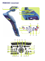
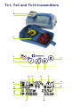
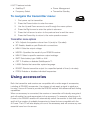
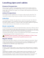
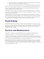
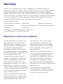
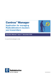
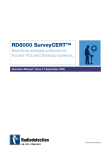
™
User Guide
Preface
About this guide
This guide provides basic operating instructions for the RD8000 receiver and transmitter.
Please read this guide in its entirety before attempting to operate the RD8000.
This guide is intended as a portable reference only. For detailed instructions, please
refer to the RD8000 operation manual, which is available for download from
www.radiodetection.com. To download the manual go to the Library section, which
is accessible via the menu; next go to Cable and Pipe Locators and then select User
Manuals and click the RD8000 Operation Manual link.
The online User Manual library also contains links to the SurveyCERT™ and eCAL™
manuals.
Copyright statement
This user guide is Copyright 2008 Radiodetection Ltd. Radiodetection is a subsidiary of
SPX Corporation, all rights reserved.
Trademarks
RD8000, RD4000, SurveyCERT, eCAL and iLOC are trademarks of Radiodetection Ltd.
The Bluetooth word mark and logos are owned by the Bluetooth SIG, Inc. and any use
of such marks by Radiodetection is under licence.
Important notices
When reporting any problems to your Radiodetection Dealer or Supplier it is important to
quote the unit serial number and the purchase date.
WARNING! This equipment is NOT approved for use in areas where hazardous
gases may be present.
WARNING! When
����������������������������
using the transmitter, switch
�����������������������������������
off the unit and disconnect
cables before removing the battery pack.
Reduce audio level before using the earpiece.
Batteries should be disposed of in accordance with your company’s work practice, and/
or any relevant laws or guidelines in your country.
This instrument, or family of instruments, will not be permanently damaged by
reasonable electrostatic discharge and has been tested in accordance with IEC 801-2.
However, in extreme cases temporary malfunction may occur. If this happens, switch off,
wait and switch on again. If the instrument still malfunctions, disconnect the batteries for
five seconds and then reinstall and switch the unit on.
WARNING! The RD8000 will detect almost all buried conductors but there are
some objects that do not radiate any detectable signal. The RD8000, or any other
electromagnetic locator, cannot detect these objects so proceed with caution.
There are also some live cables which the RD8000 will not be able to detect in
Power mode. The RD8000 does not indicate whether a signal is from a single
cable or from several in close proximity.
Wireless technology compliance
Use of iLOC™ wireless technology may be subject to national telecommunication
regulations. Check with your local government authorities for further information.
FCC and Industry Canada statements
This device complies with part 15 of the FCC Rules. Operation is subject to the following
conditions: (1) This device may not cause harmful interference, and (2) this device must
accept any interference received, including interference that may cause undesired
operation.
Changes or modifications not expressly approved by the party responsible for
compliance could void the user’s authority to operate the equipment. To comply with the
FCC RD explore compliance requirements, this device and its antenna must not be colocated or operated in conjunction with any other antenna or transmitter.
Training
Radiodetection provides training services for most Radiodetection products. Our
qualified instructors will train equipment operators or other personnel at your preferred
location or at Radiodetection headquarters. For more information go to
www.radiodetection.com or contact your local Radiodetection representative.
RD8000 receiver
2
1
3
4
5
8
11
6
7
8
18
14
12
13
9
10
14
15
30
16
31
17
19
20
28
32
21 22 23
24
29
25
26
27
Receiver features
16. Sensitivity and Log number:
Displays the log number
momentarily after a survey log is
saved to memory.
1.
Keypad.
2.
LCD.
3.
Battery compartment.
4.
Accessory slot.
17. Volume icon: Displays the volume
level.
5.
Headphone jack.
18. Current Direction arrows.
Receiver keypad
6.
Power key: Switches the unit on
and off. Opens the receiver menu.
7.
ƒ key: Selects frequency. Menu
navigation key.
8.
Up and down arrows: Adjusts the
signal gain. Scrolls through the
menu options.
9.
Antenna key: Toggles peak, null
and single antenna modes. Opens
a submenu. Toggles between
depth or current display on the
LCD.
10. Graph key: Saves SurveyCERT™
measurements.
11. Transmitter: Sends iLOC™
commands on iLOC™ enabled
receivers to iLOC™ enabled
transmitters.
Receiver screen icons
12. Indicates the signal strength and
peak marker.
13. Signal strength: Numerical
indication of signal strength.
Microvolt reading in Fault-Find
mode.
14. Peak arrows: Indicates the
location of the line relative to the
receiver.
15. Battery icon: Indicates the battery
level.
19. Radio Mode: Indicates when
Radio Mode is active.
20. Power Mode: Indicates when
Power Mode is active.
21. Accessory indicator: Indicates
when an accessory is connected.
22. CD Mode icon: Indicates when
Current Direction Mode is active.
23. A-Frame icon: Indicates when the
A-Frame is connected.
24. Operating mode indicator.
25. Bluetooth® icon: Indicates status
of Bluetooth® connection. Flashing
icon means pairing is in progress.
Solid icon indicates an established
connection is active.
26. Null / Peak / Single Mode icon:
Indicates antenna selection.
27. Sonde icon: Indicates that the
signal source is from a sonde.
28. Line icon: Indicates that the signal
source is from a line.
29. Compass: Shows the direction of
the located cable relative to the
receiver.
30. Tx status: Displays transmitter
connection status.
31. Tx standby: Indicates that the
transmitter is in Standby Mode.
32. Current / depth indicator.
Tx1, Tx3 and Tx10 transmitters
1
2
3
4
6
5
7
10
11
6
12
17
18
8
19
13
14
15
16
9
20
Transmitter features
1.
Keypad.
2.
LCD.
3.
Removable accessory tray.
Transmitter keypad
4.
Power key: Switches the unit on
and off. Opens the transmitter
menu.
5.
ƒ key: Selects frequency. Menu
navigation key.
6.
Up and down arrows: Adjusts the
output signal. Scrolls through the
menu options.
7.
Measure key: Toggles measurement
display between volts, current
and impedance. Note: displayed
measurements are based on the
currently selected mode or the
attached accessory, if applicable.
Opens a submenu.
Transmitter screen icons
8.
Battery icon: Indicates the battery
level.
9.
Alphanumeric description of
selected operation mode.
10. Standby icon: Appears when the
transmitter is in Standby Mode.
11. Output level: Displays transmitter
output power.
12. Clamp icon: Indicates when a
clamp is connected.
13. DC icon: Appears when the
transmitter is powered from a DC
source.
14. Induction indicator: Appears when
the transmitter is in Induction
Mode.
15. A-Frame (Tx3 and Tx10 only):
Indicates when the transmitter is
in Fault-Find Mode.
16. CD Mode indicator (Tx10 only):
Indicates that the transmitter is in
Current Direction Mode.
17. Voltage warning indicator:
Indicates that the transmitter is
outputting potentially hazardous
voltage levels.
18. Volume icon: Displays the volume
level.
19. Pairing icon (Tx 3B and Tx
10B only): Appears when the
transmitter and receiver are
connected via iLOC™
20. Bluetooth® icon (Tx 3B and Tx
10B only). Indicates status of
Bluetooth® connection Flashing
icon means pairing is in progress.
Before you begin
IMPORTANT! Please read this section before you attempt to operate the RD8000!
Starting the system
The receiver and transmitter are battery powered. Install good quality D-cell NiMH or
Alkaline batteries into the receiver and transmitter battery compartments. Alternatively,
you can power the transmitter from a mains or vehicle power source using a
Radiodetection supplied adapter.
To switch the receiver or the transmitter on, press and hold the keypad Power Key for
two seconds.
NOTE: Once the system is switched on, pressing the Power Key momentarily will
activate the receiver or transmitter menu.
System setup
It is important that you set up the system according to your personal preferences and
operating requirements before you conduct your first survey. You can set the system up
using the RD8000 menu as described below.
Before changing settings, ensure the receiver or transmitter is switched on by pressing
the keypad Power Key for two seconds.
Power / mains frequency
Select the correct frequency (50 or 60Hz) for your country or region’s national power
supply. To change power frequency on the transmitter and the receiver:
1.
Press the Power Key momentarily to enter the menu,
2.
Scroll to the POWER option using the arrow keys,
3.
Press the Right arrow key to enter the POWER submenu,
4.
Scroll up or down using the up and down arrows to select the correct
frequency,
5.
Press the Left arrow (ƒ on the transmitter) to accept your selection and return
to the main menu,
6.
Press the Power Key to return to the main operation screen.
Language
To select your preferred menu language:
1.
Press the Power Key on the receiver momentarily to enter the menu,
2.
Scroll to the LANG option using the arrow keys,
3.
Press the Right arrow key (
4.
Scroll up or down using the up and down arrows to select your preferred
language,
on the transmitter) to enter the LANG submenu,
5.
Press the Left arrow (ƒ on the transmitter) to accept your selection and return
to the main menu.
6.
Press the Power Key to return to the main operation screen.
Units
The RD8000 allows you to work in Metric or Imperial (US customary) units. To select
your preferred units of measurements:
1.
Press the Power Key momentarily to enter the menu,
2.
Scroll to the UNIT option using the arrow keys,
3.
Press the Right arrow key to enter the UNIT submenu,
4.
Scroll up or down using the up and down arrows to select Metric or Imperial
units,
5.
Press the Left arrow to accept your selection and return to the main menu.
6.
Press the Power Key to return to the main operation screen.
Battery
The RD8000 receiver and transmitter support both NiMH or ALK batteries. It is important
that you set the system to match the currently installed battery type to ensure optimal
performance and correct battery level indication. To set your battery type:
1.
Press the Power Key momentarily to enter the menu,
2.
Scroll to the BATT option using the arrow keys,
3.
Press the Right arrow key (
4.
Scroll up or down to select the correct battery type,
5.
Press the Left arrow (ƒ on the transmitter) to accept your selection and return
to the main menu.
6.
Press the Power Key to return to the main operation screen.
on the transmitter) to enter the BATT submenu,
The RD8000 is now ready to use.
Shutting down
To switch the receiver or the transmitter off, press and hold the keypad Power Key for
two seconds.
Using the menu
The RD8000 receiver and transmitter menus allow you to select or change system
options. Once entered, the menu is navigated using the arrow keys. Navigation is
consistent on both the transmitter and the receiver. When in the menu, most on-screen
icons will temporarily disappear and the menu options will appear in the bottom left-hand
corner of the LCD. Note that when browsing the receiver menu, the ƒ and Antenna keys
act as Left and Right arrows. When browsing the transmitter menu the ƒ and
keys
act as Left and Right arrows. The Right arrow enters a submenu and the Left arrow
returns to the previous menu.
Note: When you select an option and press the Left arrow, the option will be enabled
automatically.
To navigate the receiver menu:
1.
First power up the receiver.
2.
Press the Power button to enter the menu.
3.
Use the Up and Down arrows to scroll through the menu options.
4.
Press the Right arrow to enter the option’s submenu.
5.
Press the Left arrow to return to the previous level.
6.
Press the Power Key to return to the main operation screen.
Receiver menu options
• VOL: Adjusts the speaker volume from 0 (mute) to 3 (loudest).
• LOG: Delete, send or review saved SurveyCERT measurements. Only accessible
when Bluetooth is switched on.
• BT: Enable, disable, reset or pair Bluetooth® connections.
• UNIT: Selects metric or imperial units.
• LANG: Selects your preferred system language.
• POWER: Selects national power frequency: 50 or 60Hz.
• FREQ: Enables or disables individual frequencies.
• ALERT: Enables or disables StrikeAlert™.
• BATT: Sets battery type. NiMH or ALK.
Receiver Tx control menu (iLOC™ enabled models only)
The receiver’s Tx menu allows you to send commands to the transmitter. The Tx menu
is activated by pressing the the Tx key on the receiver. For more information on using
iLOC™, please read the operation manual.
• TXOUT: Adjust the transmitter’s power levels.
iLOC™ features include:
• SideStep™
• Power Management
• Frequency Select
• Transmitter Standby
To navigate the transmitter menu:
1.
First power up the transmitter.
2.
Press the Power button to enter the menu.
3.
Use the Up and Down arrows to scroll through the menu options.
4.
Press the Right arrow to enter the option’s submenu.
5.
Press the Left arrow to return to the previous level or exit the menu.
6.
Press the Power Key to return to the main operation screen.
Transmitter menu options
• VOL: Adjusts the speaker volume from 0 (mute) to 3 (loudest).
• BT: Enable, disable or pair Bluetooth® connections.
• MAX V: Sets the output voltage.
• MODEL: Specifies the model of your RD8000 receiver.
• MAX P: Select a specific maximum output wattage.
• BATT: Sets battery type. NiMH or ALK.
• OPT F: Enables or disables SideStepauto™.
• LANG: Selects the transmitter system language.
• BOOST: Boosts transmitter output for a specified period of time (in minutes).
• FREQ: Enables or disables individual frequencies.
Using accessories
Both the transmitter and receiver are compatible with a wide range of accessories,
including all RD4000 accessories. Use clamps to help apply a signal to pipeline or
live wire. Use an A-Frame to provide the RD8000 receiver with advanced fault-finding
capabilities.
When an accessory is connected, the receiver or transmitter will instantly recognize it
and will enable the mode appropriate to the accessory. For example, attaching an AFrame to the RD8000 receiver will automatically switch the receiver to fault-find mode
and limit the number of available frequencies to those that are compatible with the
A-Frame. The LCD will also display an icon of the accessory and will remove any nonessential icons from the screen.
Locating pipes and cables
Passive Frequencies
Passive frequency detection takes advantage of signals that are already present on
buried metallic conductors. The RD8000 supports four types of passive frequencies:
power, radio, CPS and CATV signals. You can detect these frequencies without the aid
of the transmitter.
Active Frequencies
Active frequencies are applied direct to the pipe or cable using the transmitter. The
transmitter can apply a signal using two methods: induction and direct connection.
Induction
The transmitter is placed on the ground over or near the survey area. You select the
appropriate frequency. The transmitter will then induce the signal indiscriminately to
any nearby metallic conductor. In induction mode, using higher frequencies is generally
recommended as they are induced easier onto nearby conductors.
Direct connection
In direct connection, you connect the transmitter directly to the pipe or cable you wish to
survey. The transmitter will then apply a discreet signal to the line, which you can locate
using the receiver. This method provides the best signal on an individual line and enables
the use of lower frequencies, which can be traced for longer distances.
Connecting the transmitter to a pipe or line requires the use of a direct connection lead
or clamp and a ground stake to complete the circuit.
WARNING! Direct connection to live wires is POTENTIALLY LETHAL. Direct
connections should be attempted by fully qualified personnel only!
Signal clamps
A signal clamp can apply a signal to a live line without breaking the connection. Signal
clamps are connected to the transmitter’s accessory socket. Radiodetection supplies
a range of signal clamps to suit most applications. Note that the RD8000 is fully
compatible with the RD4000 range of signal clamps.
Stethoscopes
At times, it may not be possible to use a clamp around a cable because of congestion
or inaccessibility. A stethoscope antenna should be used in place of a clamp to identify
cables.
Radiodetection supplies a range of stethoscopes to suit most applications. As with
signal clamps RD8000 is fully compatible with the R4000 range of stethoscopes.
To use a stethoscope, connect it to the receiver’s accessory socket. The receiver will
automatically detect the device and filter out location modes that are irrelevant.
Bluetooth® features
The RD8000 features Bluetooth® wireless technology that allows use of SurveyCERT™
and iLOC™ (iLOC enabled systems only). To use these features, the RD8000 receiver
must be paired with the transmitter (iLOC) or your PDA or PC (SurveyCERT™).
NOTE: For more information on Bluetooth® pairing and using SurveyCERT to analyze
survey data, please refer to the RD8000 operation manual and the SurveryCERT™
manual, which are available from www.radiodetection.com
SurveyCERT™
The RD8000 allows users to send locate data to a compatible PDA or computer using
Bluetooth® wireless technology. To save measurements to SurveyCERT™ on your PDA
you must first pair your PDA to the receiver. When used in the field with a GPS enabled
PDA, the RD8000 receiver automatically adds positional data to the recorded locate log.
Using iLOC™ (PXLB or PDLB only)
iLOC allows you to control the transmitter remotely using an advanced Bluetooth®
connection. iLOC is controlled using the receiver’s Tx menu, which is activated by
pressing the Tx key. Below is a guide to pairing the receiver and the transmitter; for more
information about using iLOC’s features, please refer to the RD8000 operation manual,
available from www.radiodetection.com
NOTE: The effective range of iLOC depends on a number of environmental factors.
Operating in noisy or built up areas may reduce the range and performance.
Pairing
To use iLOC, the transmitter and the receiver must be paired. The following procedure
shows you the steps required on both the receiver and the transmitter to successfully
pair them.
On the receiver:
1.
Power up the receiver,
2.
Press the Power Key to enter the menu,
3.
Scroll to the BT menu using the up and down arrows
4.
Press the Right arrow to enter the BT menu,
5.
Scroll to the PAIR menu using the up and down arrows and press Right arrow
to enter the PAIR menu,
6.
Scroll to the BT-TX option using the up and down arrows,
7.
Press the Left arrow and the receiver will attempt to pair with the transmitter.
NOTE Select EXIT in the PAIR menu to cancel pairing.
On the transmitter:
1.
Power up the transmitter,
2.
Press the Power Key to enter the menu,
3.
Scroll to the BT menu using the up and down arrows and press the
the BT menu,
4.
Scroll to the PAIR option using the up and down arrows,
5.
Press the ƒ key and the transmitter will attempt to pair with the receiver.
to enter
When pairing, the transmitter and receiver will display a flashing Bluetooth® icon.
When the pair is successful, the transmitter will display the pair icon and the receiver
will display a persistent Bluetooth® icon for the duration of the connection.
Once paired you can now use iLOC’s advanced features, such as SideStep and
transmitter power control, as described by the RD8000 operation manual.
Locating sondes
Sondes are self-contained, battery powered transmitters that are useful for tracking
non-metallic pipes. The RD8000 can detect a range of sonde frequencies, including
those transmitted by flexisondes and the P350 flexitrax™ crawler
(visit www.radiodetection.com for more information on other Radiodetection products).
To locate a sonde
1.
Set up the sonde according to the sonde’s user documentation. Make sure
the sonde is sufficiently powered for the duration of the survey; note the sonde’s
operating frequency,
2.
Deploy the sonde into the pipe or duct as required,
3.
On the receiver, select the sonde frequency by pressing the ƒ key until the
desired frequency is displayed on the LCD and the sonde icon is visible,
4.
Set the gain to approximately 60-80%,
A sonde radiates a peak field from the center of its axis with ghost signals at each side
of the peak. Move the receiver to one side and then along the axis of the sonde forwards
and backwards to detect the ghost signals.
Radiodetection recommends locating the ghost signals as finding them confirms the
position of the main peak. To lose the ghost signals, reduce the sensitivity of the receiver;
this should leave only the main peak signal detectable.
With the receiver sensitivity set as desired, propel the sonde along three or four meters
and stop. Place the receiver over the estimated position of the sonde and:
1.
Hold the receiver vertically with the blade in line with the sonde,
2.
Move the receiver backwards and forwards with the blade’s orientation parallel
to the sonde,
3.
Stop when the bar graph indicates a clear peak,
4.
Rotate the receiver until the blade’s orientation is perpendicular to the sonde,
stop when the bar graph indicates a clear peak,
5.
Move the receiver from side to side until the bar graph indicates a clear peak.
When the receiver locates a peak signal, it will automatically calculate the depth of the
sonde. Observe the depth reading while moving the receiver from side to side; the
lowest reading will be the correct location.
Repeat each step in smaller increments with the receiver blade resting on or near the
ground. The receiver should now be directly above the sonde with the blade in line with
the sonde; mark this position.
Propel the sonde a further three to four meters along the pipe to pinpoint its location.
Mark the location as required. Repeat the procedure along the route at similar intervals.
Note, while tracking the sonde, altering the receiver’s sensitivity is not required unless
the pipe’s depth, or the distance between receiver and sonde changes.
Fault-finding
The RD8000 PDL and PDLB have the ability to detect cable faults accurately using an
accessory A-Frame. Fault-finding works by detecting signal to ground bleeding caused
by damaged cable sheaths. For a detailed guide to fault-finding, please refer to the
RD8000 operation manual.
Service and Maintenance
Use eCAL™ to determine if your RD8000 receiver is still within its original factory
calibration settings. For more information visit www.radiodetection.com
The receiver and transmitter are designed so that they do not require regular calibration.
However, as with all safety equipment, it is recommended that they are serviced at least
once a year either at Radiodetection or an approved repair center.
Radiodetection products, including this user guide, are under continuous development
and are subject to change without notice. Go to www.radiodetection.com or contact
your local Radiodetection representative for the latest information regarding the RD8000
or any Radiodetection product.
Warranty
Subject to the conditions set out herein, Radiodetection Limited expressly and
exclusively provides the following warranty to original end user buyers of Radiodetection
products. Radiodetection products includes Radiodetection, Pearpoint, Telespec,
Bicotest, Riser Bond, Dielectric, Mark Products and Warren G-V brands. Radiodetection
hereby warrants that its products shall be free from defects in material and workmanship
for one year starting from point of sale to end customer. Extensions of this warranty
period are available where the same terms and conditions apply.
Product families include:
• Cable & Pipeline Location
• Trenchless
• Pipeline Integrity
• Pipeline Video Inspection • Ground Penetrating Radar
• Water Leak Detectors
• Cable Test
• Cable Dryers
To register for an extended warranty (3 years) go to:
www.radiodetection.com/support/warranty
Statement of warranty conditions
The sole and exclusive warranty for any
Radiodetection product found to be
defective is repair or replacement of the
defective product at Radiodetection’s
sole discretion. Repaired parts or
replacement products will be provided
by Radiodetection on an exchange basis
and will be either new or refurbished to be
functionally equivalent to new.
In the event this exclusive remedy is
deemed to have failed of its essential
purpose, Radiodetection’s liability shall
not exceed the purchase price of the
Radiodetection product. In no event will
Radiodetection be liable for any direct,
indirect, special, incidental, consequential
or punitive damages (including lost profit)
whether based on warranty, contract, tort
or any other legal theory.
Warranty services will be provided only
with the original invoice or sales receipt
(indicating the date of purchase, model
name and dealer’s name) within the
warranty period. This warranty covers
only the hardware components of the
Radiodetection product. Data storage
media or accessories must be removed
prior to submission of the product for
warranty service.
Radiodetection will not be responsible
for loss or erasure of data storage media
or accessories. Radiodetection is not
responsible for transportation costs and
risks associated with transportation of
the product. The existence of a defect
shall be determined by Radiodetection in
accordance with procedures established by
Radiodetection.
This warranty is in lieu of any other
warranty, express or implied, including
any implied warranty of merchantability or
fitness for a particular purpose.
condition and standard other than
prescribed by RD
This warranty does not cover:
a.
periodic maintenance and repair or
parts replacement due to wear and
tear
b.
consumables (components that
are expected to require periodic
replacement during the lifetime of a
product such as non-rechargeable
batteries, bulbs, etc.)
c.
damage or defects caused by use,
operation or treatment of the product
inconsistent with its intended use
d.
damage or changes to the product as
a result of:
i.
misuse, including: - treatment
resulting in physical, cosmetic or
surface damage or changes to
the product or damage to liquid
crystal displays
ii.
failure to install or use the product
for its normal purpose or in
accordance with RD instructions
on installation or use
iii.
failure to maintain the product in
accordance with RD instructions
on proper maintenance
iv. installation or use of the product
in a manner inconsistent with
the technical or safety laws or
standards in the country where it
is installed or used
v.
virus infections or use of the
product with software not
provided with the product or
incorrectly installed software
vi. the condition of or defects in
systems with which the product is
used or incorporated except other
‘RD products’ designed to be
used with the product
vii. use of the product with
accessories, peripheral equipment
and other products of a type,
viii. repair or attempted repair
by persons who are not RD
warranted and certified repair
houses
ix. adjustments or adaptations
without RD’s prior written consent,
including:
x.
i.
upgrading the product
beyond specifications or
features described in the
instruction manual, or
ii.
modifications to the product
to conform it to national
or local technical or safety
standards in countries other
than those for which the
product was specifically
designed and manufactured
neglect e.g. opening of cases
where there are no user
replaceable parts
xi. accidents, fire, liquids, chemicals,
other substances, flooding,
vibrations, excessive heat,
improper ventilation, power
surges, excess or incorrect
supply or input voltage, radiation,
electrostatic discharges including
lighting, other external forces
and impacts.
Notes
Notes
Radiodetection Ltd.
Western Drive, Bristol BS14 0AF, UK
Tel: +44 (0) 117 976 7776 Fax: +44 (0) 117 976 7775
Email: [email protected]
Radiodetection
154 Portland Road, Bridgton, ME 04009, USA
Tel: +1 (207) 647 9495 Toll Free: +1 (877) 247 3797
Fax: +1 (207) 647 9496 Email: [email protected]
www.radiodetection.com
Radiodetection products are under continuous development and are subject
to change, we reserve the right to alter or amend any published specification
without notice.
Copyright 2008 Radiodetection Limited. All rights reserved. Radiodetection Ltd.
is a subsidiary of SPX.
90/UG079ENG/02