1
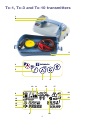
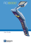
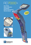
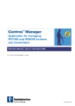
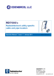
User Guide
Preface
About this guide
This guide provides basic operating instructions for the RD7000+
locator and transmitter. It also contains important safety information and
guidelines and as such should be read in its entirety before attempting to
operate the RD7000+ locator and transmitter.
It is also highly recommended to register the RD7000+ locator and transmitter
for the free 3 year extended warranty
This guide is intended as a portable quick reference only. For detailed
instructions, please refer to the RD7000+ operation manual, which can be
viewed or downloaded from the Radiodetection website at:
www.radiodetection.com. Having accessed the Radiodetection website, go to:
Downloads > Cable and Pipe Locators > User Manuals > RD7000+ Operation
Manual.
Extended Warranty
Thank you for purchasing the RD7000+ locator and transmitter.
RD7000+ locators and transmitters are covered by a 1 year warranty.
Customers can extend the warranty to 3 years by registering each product.
Registration and extended warranty are free and once registered users will
be entitled to free software updates through Centros Manager™.
To be eligible, customers must register each product within 3 months of
purchase.
Upon registration customers will receive confirmation of registration by
email and this email will include a download key, this key will be required
for software updates to your RD7000+ locator and transmitter.
When new software is released, registered users will receive a notification
email that links to the new software download page on the Radiodetection
website.
To register for extended warranty go to:
www.radiodetection.com/extendedwarranty
eCAL™
eCAL is a novel Radiodetection technique that allows the user to validate the
original factory calibration of the RD7000+ locator, providing the user with the
confidence that the locator continues to meet its original factory calibration.
eCAL also carries out a functional test on the locator providing the user with
the confidence that the locator continues to provide the same performance
as it did when it first left the factory. eCAL can be carried out on site without
the need to return the locator to a service centre, saving time and expense.
Each time the locator passes eCAL, the user can view or print a dated eCAL
validation certificate.
For a more detailed explanation of eCAL, please go to the eCAL section on
page 14.
RD7000+ locator
2
1
3
4
5
8
6
7
8
10
11
9
12
13
14
15
16
17
24
25
18
19
20
21
22
23
Locator features
1.
Keypad.
.
LCD screen.
1. Accessory indicator: Indicates when
an accessory is connected and in use.
.
Battery compartment
(USB connector inside).
1. A-Frame icon: Indicates when the
A-Frame is connected and in use.
.
Accessory socket.
0. Operating mode indicator.
.
Headphone jack.
1. Compass:
When detecting lines – shows the
direction of the located cable or pipe
relative to the locator.
When detecting sondes – shows the
direction of the longitudinal axis of the
located sonde relative to the locator.
Locator keypad
.
Power key: Switches the unit on
and off. Opens the locator menu.
.
ƒ key: Selects frequency / Closes
submenu.
.
Up and down arrows: Adjusts the
signal gain / Scrolls through menu
options.
.
Antenna key: Toggle between antenna
modes / Open submenu: Prolonged
key press toggles between depth and
current display on the LCD.
. Indicates antenna selection.
. Sonde icon: Indicates that the unit is
set to receive signals from sondes*.
. Line icon: Indicates that the unit is set
to receive signals from lines*.
. Depth or current indicator.
*Take care to set Line/Sonde appropriately,
otherwise the Compass display and depth
display will be incorrect.
Locator display icons
10. Bargraph: Indicates strength of locate
signal and peak marker.
11. Signal strength: Numerical indication
of signal strength and dB reading
when using Fault Find mode.
1. (Proportional) Left/Right arrows:
Indicates the location of the line
relative to the locator.
1. Battery icon: Indicates the battery level.
1. Volume icon: Displays the volume level.
1. Fault-Find arrows
(PL and TL models only).
1. Radio Mode: Indicates when
Radio Mode is selected.
1. Power Mode: Indicates when
Power Mode is selected.
Tx-1, Tx-3 and Tx-10 transmitters
1
2
3
4
5
7
10
11
6
12
17
18
8
19
13
14
15
16
9
20
Transmitter features
1.
Keypad.
.
LCD.
.
Removable accessory tray.
1. CD Mode indicator: Indicates that the
transmitter is in Current Direction Mode
(Tx-10 model only)
1. Voltage warning indicator: Indicates
that the transmitter is outputting
potentially hazardous voltage levels.
Transmitter keypad
.
Power key: Switches the unit on
and off. Opens the transmitter menu.
.
ƒ key: Selects frequency.
Menu navigation key.
.
Up and down arrows: Adjusts the
output level signal. Scrolls through the
menu options.
.
Measure key: Toggles measurement
display between volts and current
or resistance and power (Note:
displayed measurements are based
on the currently selected mode or
the attached accessory, if applicable)
/ Opens a submenu.
1. Volume icon: Displays the volume level.
1. Pairing icon (Tx-3B and Tx-10B only).
For use with RD8000 locators only.
0. Bluetooth® icon (Tx-3B and Tx-10B
only). For use with RD8000 locators
only.
Transmitter screen icons
.
Battery icon: Indicates the battery level.
.
Selected operation mode.
10. Standby icon: Appears when the
transmitter is in Standby Mode.
11. Output level: Displays transmitter
output level.
1. Clamp icon: Indicates when a clamp
is connected.
1. External 12V DC icon: Appears when
the transmitter is powered from an
external 12V DC source.
1. Induction indicator: Appears when the
transmitter is in Induction Mode.
1. A-Frame: Indicates when the
transmitter is in Fault-Find Mode
(Tx-3 and Tx-10 models only)
Before you begin
IMPORTANT! Please read this section before you attempt to operate the
RD7000+!
System setup
It is important that you set up the system according to your personal preferences and
operating requirements for your country before you conduct your first survey. You can
set the system up using the RD7000+ menu as described below.
Using the menu
The RD7000+ locator and transmitter menus allow you to select or change system
options. Once entered, the menu is navigated using the arrow keys. Navigation is
consistent on both the transmitter and the locator. When in the menu, most on-screen
icons will temporarily disappear and the menu options will appear in the bottom left-hand
corner of the LCD. Note that when browsing the locator menu, the
and
keys act
as left and right arrows. When browsing the transmitter menu the
and
keys act
as left and right arrows. The right arrow enters a submenu and the left arrow accepts the
selection and returns to the previous menu.
Locator menu options
•
VOL: Adjust the speaker volume from 0 (mute) to 3 (loudest).
•
BATT: Set battery type. NiMH or ALK.
•
ALERT: Enable or disable StrikeAlert™.
•
FREQ: Enable or disable individual frequencies.
•
ANT: Enable or disable any antenna mode with the exception of Peak.
•
POWER: Set national power frequency: 50 or 60Hz.
•
LANG: Select your preferred system language.
•
CAL: Displays the date of the last factory calibration.
•
UNIT: Depth readings in metric or imperial units.
To navigate the locator menu:
1.
First power up the locator.
.
Momentarily press the
.
Use the
.
Press the
.
Use the
.
Press the
.
You may continue to scroll through other menu options and make selections using
instructions 3 to 6 above or alternatively momentarily press the
key to exit the
menu and return to the main operating screen.
or
key to enter the menu.
arrows to scroll through the menu options.
key to enter the option’s submenu.
or
arrows to select the required selection.
key to accept your selection and return to the main menu.
Transmitter menu options
•
VOL: Adjust the speaker volume from 0 (mute) to 3 (loudest).
•
BT: Enable, disable or pair Bluetooth® connections (Tx-3B and Tx-10B only).
•
MAX V: Set the output voltage to LOW or High.
•
MODEL: Set the transmitter to work with a specific model of RD7000+ locator
•
MAX P: Select a specific maximum output power.
•
BATT: Set battery type. ALK, NiMH or Lithium Ion.
•
OPT F: Enable or disable SideStepauto™.
•
LANG: Select the transmitter system language.
•
BOOST: Boost transmitter output for a specified period of time (Tx-10 model only).
•
FREQ: Enable or disable individual frequencies.
To navigate the transmitter menu:
1.
First power up the transmitter.
.
Momentarily press the
.
Use the
.
Press the
.
Use the
.
Press the
.
You may continue to scroll through other menu options and make selections using
instructions 3 to 6 above or alternatively momentarily press the
key to exit the
menu and return to the main operating screen.
or
key to enter the menu.
arrows to scroll through the menu options.
key to enter the option’s submenu.
or
arrows to select the required selection.
key to accept your selection and return to the main menu.
Examples of using the menu, selecting options and
making changes
Power / mains frequency (locator only)
Select the correct frequency (50 or 60Hz) for your country or region’s national power
supply. To change power frequency on the locator:
1.
Press the
key momentarily to enter the menu.
.
Press the
or
.
Press the
locator key to enter the POWER submenu.
.
Use the
.
Press the
or
keys until POWER is displayed.
keys to select the correct frequency.
key to accept your selection.
Language
To select your preferred menu language:
1.
Press the
key momentarily to enter the menu.
.
Press the
or
.
Press the locator
.
Press the
or
.
Press the
key to accept your selection and return to the main menu.
.
Press the
key momentarily to return to the main operation screen.
keys until LANG is displayed.
key or transmitter
key to enter the LANG submenu.
arrows to select your preferred language.
Depth Measurement Units (locator only)
The RD7000+ allows you to work in Metric or Imperial units. To select your preferred
units of measurement:
1.
Press the
key momentarily to enter the menu.
.
Press the
or
.
Press the
key to enter the UNIT submenu.
.
Press the
or
.
Press the
key to accept your selection and return to the main menu.
.
Press the
key momentarily to return to the main operation screen.
keys until UNIT is displayed.
arrows to select Metric or Imperial units.
Battery
The RD7000+ locator and transmitter support Alkaline, NiMH or Lithium Ion batteries.
It is important that you set the system to match the currently installed battery type to
ensure optimal performance and correct battery level indication. To set your battery type:
1.
Press the
key momentarily to enter the menu.
.
Press the
or
keys until BATT is displayed.
10
.
Press the locator
key or transmitter
key to enter the BATT submenu.
.
Press the
or
.
Press the
key to accept your selection and return to the main menu.
.
Press the
key momentarily to return to the main operation screen.
keys to select the correct battery type.
Locating pipes and cables
Passive Frequencies
Passive frequency detection takes advantage of signals that may already be present on
buried metallic conductors. The RD7000+ supports three types of passive frequencies:
Power, Radio and CPS (Cathodic Protection Signal). You may detect these frequencies
without the aid of the transmitter.
Active Frequencies
Active frequencies are applied directly to the pipe or cable using the transmitter and
are the preferred method of applying a signal to a conductor using the transmitter. The
transmitter can apply a signal using two methods: induction and direct connection.
Induction
The transmitter is placed on the ground over or near the survey area. You select the
appropriate frequency. The transmitter will then induce the signal to any nearby metallic
conductors. In induction mode, using higher frequencies is generally recommended as
they are induced more easily onto conductors.
Direct connection
In direct connection, you connect the transmitter output directly to the pipe or to the
conductor of the cable you wish to survey. The transmitter will then apply an active
frequency signal to the line, which you can locate using the locator. This method
provides the best signal on an individual line and enables the use of lower frequencies,
which can be traced for longer distances.
Connecting the transmitter to a pipe or line requires the use of a direct connection lead
connected to the accessory socket of the transmitter. The red lead is connected to the
pipe or cable and the black lead connected to an earth stake to complete the electrical
circuit.
WARNING! Direct connection to live wires is POTENTIALLY LETHAL.
Direct connections should be attempted by fully qualified personnel only!
11
Signal clamps
When it is not possible to connect to a pipe or cable using a direct connection lead, a
transmitter signal clamp can be connected to the accessory socket of the transmitter
and the output signal can be applied. This is particularly useful with live cables as it
removes the need to disable the power and break into the line.
To locate or indentify individual lines a locator signal clamp can be connected to the
accessory socket of the locator and can be clamped around individual cables or pipes
that are bunched together.
Radiodetection supplies a range of signal clamps to suit many applications.
Stethoscopes
At times, it may not be possible to use a locator to locate or identify a particular target
line due to inaccessibility. In these situations a stethoscope antenna should be used to
locate or identify individual target lines.
Radiodetection supplies a range of stethoscopes to suit most applications. To use a
stethoscope, connect it to the locators accessory socket. The locator will automatically
detect the device and filter out location modes that are irrelevant.
Locating sondes
Sondes are battery powered transmitters that are useful for tracking non-metallic pipes
and can be fitted to flexrods and inserted into pipes and ducting etc. The RD7000+ PL,
DL and TL models can detect a range of sonde frequencies, including those transmitted
by FlexiSondes and the P350 Flexitrax™ crawler.
For a detailed guide on locating sondes, please refer to the RD7000+ Operation Manual.
Fault-finding
The RD7000+ TL and PL models have the ability to detect sheath cable faults
accurately using an accessory A-Frame. The Tx-3 and Tx-10 transmitters provide a fault
finding signal that can be detected with an A-frame, which occurs whenever there is
damage to cable sheaths.
For a detailed guide to fault-finding, please refer to the RD7000+ operation manual.
Using accessories
Radiodetection have designed a range of accessories to use with the RD7000+ locators
and transmitters. These accessories can be used on a wide range of applications for
applying signals to target lines, fault finding on cables, identifying individual target lines
and locating plastic pipes etc. Applicable RD4000 accessories are compatible with the
RD7000+ locator and transmitters.
For detailed information on accessories please see the RD7000+ operation manual
or go to www.radiodetection.com.
12
Centros Manager™
Centros Manager is a Radiodetection PC application which is available as a free
download. From time to time Radiodetection will release new software for the RD7000+
locator and transmitter which may improve performance, stability and may include new
features. The latest software is contained within Centros Manager and to download the
latest software you must register for extended warranty (see page 3 for details). Once
registered you will receive an email when new versions of software are available and you
may also carry out an eCAL to validate the calibration and functionally test the RD7000+
locator.
Installing Centros Manager
Note: Before download you are advised to view or download the Centros Manager
operation Manual by going to www.radiodetection.com/centrosmanager.
Note: When you install Centros Manager onto a PC, the following message may
be displayed: “You need to log in as Administrator”. If this message is displayed,
the installation of the program will not complete. You will need to log on as an
Administrator or ask a user with Administration Rights to install the program on your
behalf. Having successfully installed Centros Manager, the Administrator will need to
carry out the instructions in Section 7.1 of the Centros Manager Operation Manual if
they wish users without Administrator Rights to use Centros Manager.
1.
Go to: www.radiodetection.com/centrosmanager.
.
Click on the link to download Centros Manager and a File Download Window will
appear. You will have a choice of either, Run or Save.
Run: Centros Manager will automatically install.
Save: you will be given the option to save Centros Manager to a destination of your
choice. Once you select the destination, the Centros Manager executable program
will download to that destination. Once completed you will have the option to Run
or Open Folder. At this stage Centros Manager has not been installed so you can
either select Run and Centros Manager will automatically install, or you can choose
to Open Folder. When you open the folder the Centros Manager executable file will
be available. To install double click on this file.
.
When Centros Manager is installed run from the Windows Start menu under
Programs or alternatively, use the Centros Manager shortcut on your desk top if
you have opted to have this during installation of Centros Manager.
Note: Once Centros Manager is open, click on Help to open the Centros Manager
Operation Manual.
13
eCAL™
Each time you use a locator you want to be confident that the equipment you are using
continues to perform to the same standard as it did when it first left the factory. eCAL
provides users with the following features which maybe accessed and carried out on
site, without the need to return the locator to a service centre.
•
Check the validation of the RD7000+ with the original stored factory calibration
results.
•
Carrying out a functional check.
•
Retrieving original factory calibration certificate or previous eCAL validation certificates.
To validate your RD7000+, you must first carry out the following:
1.
Register your RD7000+ locator at www.radiodetection.com/extendedwarranty.
See page 3 for more details.
.
Purchase an eCAL key at www.radiodetection.com/ecal or alternatively contact
your local Radiodetection representative.
.
Download Centros Manager at www.radiodetection.com/centrosmanager.
See page 13 for details.
Using eCAL to validate the RD7000+
1.
Connect the RD7000+ via the USB connector inside the battery compartment to
a suitable USB port on a PC or laptop.
.
Switch on the RD7000+ (no segments will be lit but the backlight will be on).
.
Open Centros Manager and click on Locator eCAL Validation.
.
Copy the eCAL key (received in your confirmation email when purchasing the
eCAL key) and click on Load Validation Key icon and paste the eCAL key.
.
Click on Run eCAL Validation. A message box will automatically open informing
you of progress.
.
In less than 3 minutes the eCAL Validation Status will be displayed. To view or print
the certificate, locate the serial number of the RD7000+ within the Unit Manager
window and expand the contents. Expand Calibration History and double click on
the latest date to display the certificate of validation.
14
Using eCAL to retrieve the original factory
calibration certificate
The original factory calibration results for the RD7000+ locator can be retrieved from
the unit. Each time the RD7000+ is calibrated either at Radiodetection or an approved
Radiodetection service centre, the calibration results are stored within the locator. To
retrieve the results and print a certificate, carry out the following:
Note: You do not need to purchase an eCAL validation key to retrieve the original
factory calibration certificate.
1.
Register your RD7000+ locator by going to:
www.radiodetection.com/extendedwarranty. See page 3 for more details.
.
Download Centros Manager by going to:
www.radiodetection.com/centrosmanager. See page 13 for details.
.
Connect the RD7000+ via the USB connector inside the battery compartment
to a suitable USB port on a PC or laptop.
.
Switch on the RD7000+ (no segments will be lit but the backlight will be on).
.
Open Centros Manager and click on Locator eCAL Validation.
.
Click on Get Original Calibration Data and a message box will automatically pop
up displaying the progress.
.
In less than 3 minutes the original calibration certificate will be available to view
or print, locate the serial number of the RD7000+ within the Unit Manager window
and expand the contents. Expand Calibration History and click on each date.
When you click on each date, the type of certificate, whether an eCAL validation or
original factory calibration, together with date and serial number will be displayed.
By clicking on this window, the certificate will be displayed and you can choose to
print this certificate.
15
Important notices
When reporting any problems to your Radiodetection Dealer or Supplier it is important to
quote the unit serial number and the purchase date.
WARNING! This equipment is NOT approved for use in areas where
hazardous gases may be present.
WARNING! When using the transmitter, switch off the unit and disconnect
cables before removing the battery pack.
Reduce audio level before using the earpiece.
Batteries should be disposed of in accordance with your company’s work practice,
and/or any relevant laws or guidelines in your country.
This instrument, or family of instruments, will not be permanently damaged by
reasonable electrostatic discharge and has been tested in accordance with IEC 801-2.
However, in extreme cases temporary malfunction may occur. If this happens, switch
off, wait and switch on again. If the instrument still malfunctions, disconnect the
batteries for five seconds and then reinstall and switch the unit on.
WARNING! The RD7000+ will detect almost all buried conductors
but there are some objects that do not radiate any detectable signal. The
RD7000+, or any other electromagnetic locator, cannot detect these objects
so proceed with caution. There are also some live cables which the RD7000+
will not be able to detect in Power mode. The RD7000+ does not indicate
whether a signal is from a single cable or from several in close proximity.
Copyright statement
Copyright 2010 Radiodetection Ltd - SPX Corporation. All rights reserved.
Radiodetection is a subsidiary of SPX Corporation.
SPX and Radiodetection are trademarks of Radiodetection Ltd. and SPX Corporation.
Due to a policy of continued development, we reserve the right to alter or amend any
published specification without notice.
This document is protected by copyright and may not be copied, reproduced,
transmitted, modified or used, in whole or in part, without the prior written consent of
Radiodetection Ltd.
16
Trademarks
RD7000, RD7000+, RD8000, RD4000, flexitrax, SurveyCERT, StrikeAlert, SideStep and
eCAL are trademarks of Radiodetection Ltd.
FCC and Industry Canada statements
This device complies with part 15 of the FCC Rules. Operation is subject to the following
conditions: (1) This device may not cause harmful interference, and (2) this device must
accept any interference received, including interference that may cause undesired
operation.
Changes or modifications not expressly approved by the party responsible for
compliance could void the user’s authority to operate the equipment. To comply with
the FCC RD explore compliance requirements, this device and its antenna must not
be co-located or operated in conjunction with any other antenna or transmitter.
Training
Radiodetection provides training services for most Radiodetection products. Our
qualified instructors will train equipment operators or other personnel at your preferred
location or at Radiodetection headquarters. For more information go to:
www.radiodetection.com or contact your local Radiodetection representative.
Service and Maintenance
The locator and transmitter are designed so that they do not require regular calibration.
However, as with all safety equipment, it is recommended that they are serviced at least
once a year either at Radiodetection or an approved repair center.
Radiodetection products, including this user guide, are under continuous development
and are subject to change without notice. Go to: www.radiodetection.com or contact
your local Radiodetection representative for the latest information regarding the
RD7000+ or any Radiodetection product.
17
Warranty
Subject to the conditions set out herein, Radiodetection Limited expressly and
exclusively provides the following warranty to original end user buyers of Radiodetection
products. Radiodetection products include Radiodetection, Pearpoint, Telespec,
Bicotest, Riser Bond, Dielectric, Mark Products and Warren G-V brands. Radiodetection
hereby warrants that its products shall be free from defects in material and workmanship
for one year starting from point of sale to end customer. Extensions of this warranty
period are available where the same terms and conditions apply.
Product families include:
• Cable & Pipeline Location
• Trenchless
• Water Leak Detectors
• Pipeline Integrity
• Pipeline Video Inspection • Ground Penetrating Radar
• Cable Test
• Cable Dryers
To register for an extended warranty (3 years) go to:
www.radiodetection.com/extendedwarranty
Statement of warranty conditions
The sole and exclusive warranty for any Radiodetection product found to be defective
is repair or replacement of the defective product at Radiodetection’s sole discretion.
Repaired parts or replacement products will be provided by Radiodetection on an
exchange basis and will be either new or refurbished to be functionally equivalent to new.
In the event this exclusive remedy is deemed to have failed of its essential purpose,
Radiodetection’s liability shall not exceed the purchase price of the Radiodetection
product. In no event will Radiodetection be liable for any direct, indirect, special,
incidental, consequential or punitive damages (including lost profit) whether based on
warranty, contract, tort or any other legal theory.
Warranty services will be provided only with the original invoice or sales receipt
(indicating the date of purchase, model name and dealer’s name) within the warranty
period. This warranty covers only the hardware components of the Radiodetection
product. Data storage media or accessories must be removed prior to submission of the
product for warranty service.
Radiodetection will not be responsible for loss or erasure of data storage media
or accessories. Radiodetection is not responsible for transportation costs and
risks associated with transportation of the product. The existence of a defect shall
be determined by Radiodetection in accordance with procedures established by
Radiodetection.
This warranty is in lieu of any other warranty, express or implied, including any implied
warranty of merchantability or fitness for a particular purpose.
18
This warranty does not cover:
a.
Periodic maintenance and repair or parts replacement due to wear and tear.
b.
Consumables (components that are expected to require periodic replacement
during the lifetime of a product such as non rechargeable batteries, bulbs, etc.).
c.
Damage or defects caused by use, operation or treatment of the product
inconsistent with its intended use.
d.
Damage or changes to the product as a result of:
i.
Misuse, including: - treatment resulting in physical, cosmetic or surface damage
or changes to the product or damage to liquid crystal displays.
ii.
Failure to install or use the product for its normal purpose or in accordance with
Radiodetection instructions on installation or use.
iii.
Failure to maintain the product in accordance with Radiodetection instructions
on proper .
iv. Installation or use of the product in a manner inconsistent with the technical or
safety laws or standards in the country where it is installed or used.
v.
Virus infections or use of the product with software not provided with the
product or incorrectly installed software.
vi. The condition of or defects in systems with which the product is used or
incorporated except other ‘Radiodetection products’ designed to be used
with the product.
vii. Use of the product with accessories, peripheral equipment and other products
of a type, condition and standard other than prescribed by Radiodetection.
viii. Repair or attempted repair by persons who are not Radiodetection warranted
and certified repair houses.
ix. Adjustments or adaptations without Radiodetection’s prior written consent,
including:
x.
i.
upgrading the product beyond specifications or features described in the
instruction manual, or
ii.
modifications to the product to conform it to national or local technical or
safety standards in countries other than those for which the product was
specifically designed and manufactured.
Neglect e.g. opening of cases where there are no user replaceable parts.
xi. Accidents, fire, liquids, chemicals, other substances, flooding, vibrations,
excessive heat, improper ventilation, power surges, excess or incorrect supply
or input voltage, radiation, electrostatic discharges including lighting, other
external forces and impacts.
19
Notes
20
Notes
21
America
Radiodetection
154 Portland Road, Bridgton, ME 04009, USA
Tel: +1 (207) 647 9495 Toll Free: +1 (877) 247 3797 Fax: +1 (207) 647 9496
Email: [email protected] Web: www.radiodetection.com
Pearpoint
72055 Corporate Way, Thousand Palms CA 92276, USA
Tel: +1 800 688 8094 Tel: +1 760 343 7350 Fax: +1 760 343 7351
Email: [email protected] Web: www.radiodetection.com
Radiodetection (Canada)
344 Edgeley Boulevard, Unit 34, Concord, Ontario L4K 4B7, Canada
Tel: +1 (905) 660 9995 Toll Free: +1 (800) 665 7953 Fax: +1 (905) 660 9579
Email: [email protected] Web: www.radiodetection.com
Europe
Radiodetection Ltd (UK)
Western Drive, Bristol BS14 0AF, UK
Tel: +44 (0) 117 976 7776 Fax: +44 (0) 117 976 7775
Email: [email protected] Web: www.radiodetection.com
Radiodetection (France)
13 Grande Rue, 76220, Neuf Marché, France
Tel: +33 (0) 2 32 89 93 60 Fax: +33 (0) 2 35 90 95 58
Email: [email protected] Web: http://fr.radiodetection.com
Radiodetection (Benelux)
Industriestraat 11, 7041 GD ’s-Heerenberg, Netherlands
Tel: +31 (0) 314 66 47 00 Fax: +31 (0) 314 66 41 30
Email: [email protected] Web: http://nl.radiodetection.com
Radiodetection (Germany)
Groendahlscher Weg 118, 46446 Emmerich am Rhein, Germany
Tel: +49 (0) 28 51 92 37 20 Fax: +49 (0) 28 51 92 37 520
Email: [email protected] Web: http://de.radiodetection.com
Asia-Pacific
Radiodetection (Asia-Pacific)
Room 708, CC Wu Building, 302-308 Hennessy Road, Wan Chai, Hong Kong SAR, China
Tel: +852 2110 8160 Fax: +852 2110 9681
Email: [email protected] Web: www.radiodetection.com
Radiodetection (China)
Hongfu Mansion, Room 61622, Zheng Ge Zhuang, Bei Qi Jia Town, Chang Ping District
Beijing 102209, China
Tel: +86 (0) 10 8975 5540 Fax: +86 (0) 10 8975 5640
Email: [email protected] Web: http://cn.radiodetection.com
Radiodetection (Australia)
Unit 14, 5-7 Prosperity Parade, Warriewood NSW 2102, Australia
Tel: +61 (0) 2 9979 8555 Fax: +61 (0) 2 9979 7733
Email: [email protected] Web: www.radiodetection.com
Copyright 2010 Radiodetection Ltd - SPX Corporation. All rights reserved.
Radiodetection is a subsidiary of SPX Corporation. SPX and Radiodetection are
trademarks of Radiodetection Ltd. and SPX Corporation. Due to a policy of continued
development, we reserve the right to alter or amend any published specification
without notice. This document may not be copied, reproduced, transmitted, modified
or used, in whole or in part, without the prior written consent of Radiodetection Ltd.
90/UG088INT/01