1
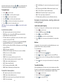
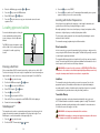
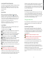
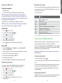
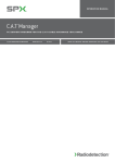
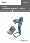
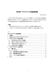
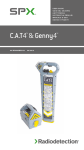
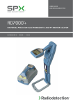
U ser G uide
RD8100™
M U LTI FU N CTI ON PR E CI S I ON CAB LE AN D PI PE LO CATOR S
90/ UG104I NT/01
ISSUE 1
07/2015
ENGLISH4
3 Year Extended Warranty
About this guide
CAUTION: This guide provides basic operating instructions for the RD8100
locator and transmitter. It also contains important safety information and
guidelines and as such should be read in its entirety before attempting to
operate the RD8100 locator and transmitter.
This guide is intended as a quick reference guide only. For detailed instructions,
including the use of accessories, help with eCert™, CALSafe™, SurveyCERT™ and
usage-logging please refer to the RD8100 locator operation, SurveyCERT and
RD Manager™ manuals, which are available for download from www.radiodetection.com.
The online User Manual library also contains links to the SurveyCERT and
RD Manager manuals.
RD8100 locators and transmitters are covered by a 1 year warranty as standard.
Customers can extend their warranty period to a total of 3 years by registering
their products within 3 months of purchase.
Registration is carried out using the RD Manager PC software which can be
downloaded from the Radiodetection website. Visit www.radiodetection.com/
RDManager.
You can also register your product(s) by sending an email to [email protected],
including the following details:
• Serial number of each product to be registered
• Date of purchase
• Company name & address, including country
• Contact name, email address & telephone number
• Country of residence.
WARNING! Direct connection to live conductors is POTENTIALLY LETHAL.
Direct connections to live conductors should be attempted by fully qualified
personnel only using the relevant products that allow connections to energized
lines.
WARNING! The transmitter is capable of outputting potentially lethal
voltages. Take care when applying signals to any pipe or cable and be sure to
notify other technicians who may be working on the line.
WARNING! Reduce audio level before using headphones to avoid damaging
your hearing.
WARNING! This equipment is NOT approved for use in areas where
hazardous gases may be present.
WARNING! When using the transmitter, switch off the unit and disconnect
cables before removing the battery pack.
WARNING! The RD8000 locator will detect most buried conductors but
there are some objects that do not radiate any detectable signal. The RD8100,
or any other electromagnetic locator, cannot detect these objects so proceed
with caution. There are also some live cables which the RD8100 will not be able
to detect in Power mode. The RD8100 does not indicate whether a signal is
from a single cable or from several in close proximity.
WARNING! Batteries can get hot after prolonged use at full output power.
Take care while replacing or handling batteries.
4
From time to time Radiodetection may release new software to improve the
performance or add new functionality to its products. By registering, users will
benefit from email alerts advising about new software and special offers related to
its product range.
Users can opt-out at any time from receiving software and technical notifications,
or just from receiving marketing material by contacting Radiodetection.
eCert and Self-Test
The RD8100 locator is safety equipment which should be regularly checked to
ensure its correct operation.
eCert provides a thorough test of the RD8100’s locating circuitry, and supplies a
Radiodetection Calibration Certificate when a positive test result is obtained.
To run an eCert, the locator should be connected to an internet-enabled PC on
which the RD Manager software is installed.
Refer to the RD Manager operation manual for further details. Additional purchase
may be required.
RD8100 locators incorporate an Enhanced Self-Test feature. In addition to the
typical checks for display and power functions, the RD8100 applies test signals to
its locating circuitry during a Self-Test to check accuracy and performance.
We recommend that a self-test is run at least weekly, or before each use.
5
ENGLISH
Preface
Locator features
8
1
3
2
1. Keypad.
23. Radio Mode icon.
2. LCD with auto backlight.
24. Power Mode icon.
3. Speaker.
25. Accessory / Measurement icon.
4. Battery compartment.
26. CD Mode icon.
5. Optional Lithium-Ion battery pack.
27. A-Frame icon.
6. Accessory connector.
28. Frequency / current / menu readout.
7. Headphone connector.
29. Bluetooth status icon:
Flashing icon means pairing is in
progress. Solid icon indicates a
connection is active.
8. Bluetooth module antenna.
®
4
9. USB port
(inside battery compartment).
9
6
7
30. Antenna mode icon:
Indicates antenna selection:
Peak / Null / Single, Peak+ / Guidance.
Locator keypad
10. Power key.
5
31. Sonde icon: Indicates that a sonde
signal source is selected.
11. Frequency key.
12. Up and down arrows.
32. Line icon: Indicates that a line signal
source is selected.
13. Antenna key.
15
12
14. Survey key.
33. Compass: Shows the orientation
of the located cable or sonde relative
to the locator.
15. Transmitter key.
Locator screen icons
10
11
34. Transmitter communication status
– confirms successful iLOC™
communication.
16. Signal strength bargraph with
peak marker.
35. Transmitter standby indicator.
17. Signal strength readout.
22
18
16 17
12
18
19
34
35
20
21
23
24
13
14
GPS active, seeking satellite lock
37
GPS satellite lock acquired
38
3-5 satellites in view
32
6-8 satellites in view
36
9-11 satellites in view
36. Depth readout.
18. Null / Proportional Guidance arrows.
19. Battery level.
GPS equipped locators only:
20. Sensitivity readout / Log number.
37. GPS Status.
21. Volume level.
38. GPS Signal quality.
22. Current Direction arrows.
12 or more satellites in view
25
26
27
28
33
29
30
31
6
7
ENGLISH
RD8100 locator
Transmitter features
15. Clamp icon: Indicates when a signal
clamp or other accessory is connected.
1. Keypad.
2. LCD.
2
1
16. DC Power connected indicator.
3. Removable accessory tray.
17. Induction mode indicator.
4. D-cell battery tray.
18. A-Frame: Indicates when the
transmitter is in Fault-Find Mode.
5. Optional Lithium-Ion battery pack.
6. Bluetooth module antenna.
6
19. CD Mode: Indicates that the transmitter
is in Current Direction Mode.
Transmitter keypad
8. Frequency key.
20. Voltage warning indicator: Indicates
that the transmitter is outputting
potentially hazardous voltage levels.
9. Up and down arrows.
21. Volume level indicator.
7. Power key.
3
10. Measure key.
iLOC Enabled transmitters only:
Transmitter screen icons
5
22. Pairing icon: Appears when the
transmitter and locator are connected
via iLOC.
11. Battery level indicator.
4
12. Operation mode readout.
23. Bluetooth icon: Indicates status of
Bluetooth connection. Flashing icon
means pairing is in progress.
13. Standby icon.
14. Output level indicator.
7
9
8
10
13
14
15
20
21
11
22
16
17
18
19
12
23
8
9
ENGLISH
Tx-1, Tx-5 and Tx-10 transmitters
Before you begin
Switch the locator or transmitter on by pressing the
function as follows:
IMPORTANT!
This guide is intended to be a quick reference guide. We recommend you read the
full operation manual before you attempt to operate the RD8100 locator.
key. Once powered up, the keys
Locator keys
First use
KEY
● S H O RT PR E S S
●■■■● LON G P R E S S
Enter the menu
Switch power off
Scroll through locate frequencies
from low to high
When using active frequencies:
Toggles peak, peak+, null, broad peak
and guidance antenna modes.
In Power Mode:
Scrolls through Power Filters™ for improved
discrimination of parallel or strong power
signals
and
The RD8100 locators and transmitters can be powered by D-cell alkaline batteries, D-cell
NiMH batteries, or by an accessory Li-Ion (Li-Ion) battery pack.
To fit the D cell batteries in the locator, open the battery compartment and insert two
D-Cell Alkaline or NiMH batteries, taking care to align the positive (+) and negative (-)
terminals as indicated.
SideStep™ (see ‘iLOC’ section)
When using Current Direction™:
Perform a CD Reset
In Peak+ antenna mode:
Switch between Guidance and Null arrows
Alternatively, you can power the transmitter from a mains or vehicle power source using a
Radiodetection supplied optional accessory adapter.
Increase and decrease gain.
RD8100 automatically sets gain to
mid-point when pressed
Rapidly increase and decrease gain steps
in 1dB increments
Take a Survey Measurement and send
over Bluetooth if paired
–
Send an iLOC command to a paired
transmitter
Enter the Transmitter power setting menu
for use over iLOC
Rechargeable battery packs
Lithium-Ion battery packs are available for both locators and transmitters, providing
superior performance over traditional alkaline batteries. To fit these rechargeable packs,
follow the instructions provided with each pack.
Checking your system software version
Transmitter keys
KEY
To fit the D cell batteries in the transmitter, unlatch the accessory tray. The battery
compartment is located underneath the transmitter body. Use the turnkey to unlatch the
battery compartment. Insert eight D-Cell Alkaline or NiMH batteries, taking care to align
the positive (+) and negative (-) terminals as indicated.
If you wish to check which version of software is running on your locator, press and
hold the
key when switching the locator on. This information may be asked for when
contacting Radiodetection or your local representative for technical support.
● S H O RT PR E S S
●■■■● LON G P R E S S
Enter the menu
Switch Power off
Scroll through locate frequencies
from low to high
–
Take voltage and impedance measurements
using the currently selected frequency
Take voltage and impedance
measurements at a standardized frequency
Adjusts the output signal
Select standby
Transmitters automatically show their software version on startup.
and
System setup
/ maximum standard
power
Tip: to scroll through frequencies from high to low, hold
(applies to both locators and transmitters).
10
while pressing the
button
It is important that you set up the system according to regional / operational requirements
and your personal preferences before you conduct your first survey. You can set the
system up using the menus as described below.
Setting up your system
The RD8100 locator and transmitter menus allow you to select or change system options.
Once entered, the menu is navigated using the arrow keys. Navigation is consistent on both
the transmitter and the locator. When in the menu, most on-screen icons will temporarily
disappear and the menu options will appear in the bottom left-hand corner of the display.
The right arrow enters a submenu and the left arrow returns to the previous menu.
11
ENGLISH
Keypad actions and shortcuts
To navigate menus:
1. Press the
2. Use the
3. Press the
4. Use the
key to enter the menu.
or
keys to scroll through the menu options.
key to enter the option’s submenu.
or
keys to scroll through the submenu options.
5. Press the
key to confirm a selection and return to the previous menu.
6. Press the
key to return to the main operation screen.
NOTE: When you select an option and press the
automatically.
key, the option will be enabled
Locator menu options
•
OPT F: Run SideStepauto™ to auto-select a locate frequency for the connected
utility.
•
BATT: Set battery type: ALK, NiMH or Li-ION and enable / disable Eco mode.
•
MAX P: Set the transmitter to output its maximum wattage.
•
MODEL: Match the transmitter setting to the model of your locator.
•
MAX V: Set the output voltage to maximum (90V).
•
BT: Enable, disable or pair Bluetooth connections (Bluetooth models only).
Examples of using the menu, selecting options and
making changes:
Locator mains power frequency
To select the correct frequency (50 or 60Hz) for your country or region’s power supply:
1. Press the
key to enter the menu.
•
VOL: Adjust the speaker volume from 0 (mute) to 3 (loudest).
2. Scroll to the POWER menu using the
•
DATA: Delete, send or review saved SurveyCERT measurements and enable or
disable the Bluetooth communication channel.
3. Press the
4. Use the
•
BT: Enable, disable, reset or pair Bluetooth connections. Also defines the protocol
used when connecting to a PC or PDA.
5. Press the
screen.
•
GPS: Enable or disable the internal GPS module and enable/disable SBAS GPS
augmentation (GPS models only) – or select an external GPS source.
Batteries
•
CDR: Perform a Current Direction (CD) Reset. (Alternatively press and hold the
key when in CD mode).
It is important to set the system to match the currently installed battery type to ensure
optimal performance and correct battery level indication.
•
UNITS: Select metric or imperial units.
To set your battery type:
•
INFO: Run a Self-Test, display the date of the most recent service recalibration
(M CAL) or the most recent eCert calibration.
1. Press the
2. Scroll to the BATT menu using the
•
LANG: Select menu language.
3. Press the
•
POWER: Select local power network frequency: 50 or 60Hz.
•
ANT: Enable or disable any antenna mode with the exception of Peak.
4. Scroll up or down to select the correct battery type (Alkaline, Nickel-metal Hydride or
Lithium-Ion).
•
FREQ: Enable or disable individual frequencies.
•
ALERT: Enable or disable StrikeAlert .
•
BATT: Set battery type: Alkaline, NiMH or Li-ION.
Transmitter Eco Mode
•
COMP: Enable or disable display of the Compass feature.
Transmitter menu options
When using alkaline batteries, Eco mode can be selected to maximize run time. When
Eco mode is selected the transmitter automatically reduces its maximum power output as
battery levels run low. Eco mode is switched off by default. To Enable Eco Mode:
•
VOL: Adjust the speaker volume from 0 (mute) to 3 (loudest).
1. Press the
•
FREQ: Enable or disable individual frequencies.
2. Scroll to the BATT menu using the
•
BOOST: Boost transmitter output for a specified period of time (in minutes).
3. Press the
•
LANG: Select menus language.
™
12
5. Press the
screen.
keys.
or
key to enter the POWER menu.
or
keys to select the correct mains frequency.
key twice to accept your selection and return to the main operation
key to enter the menu.
key (locator) or the
or
arrows.
key (transmitter) to enter the BATT menu.
key twice to accept your selection and return to the main operation
key to enter the menu.
or
key to enter the BATT menu.
13
arrows.
ENGLISH
Note that when browsing the locator menu, the
and
keys act as left and right arrows.
When browsing the transmitter menu, the
and
keys act as left and right arrows.
5. Press the
arrows.
or
or
arrows.
7. Press the
key three times to accept your selection and return to the main
operation screen.
Locating pipes and cables
For more detailed descriptions of using the
locator and transmitter, and for detailed
locate techniques, refer to the Operation
Manual.
In direct connection, you connect the transmitter directly to the pipe or cable you wish to
survey using the red Direct Connect lead supplied. The black lead is generally connected
to earth using the supplied ground stake.
The transmitter will then apply a discrete signal to the line, which you can trace using the
locator. This method provides the best signal on an individual line and enables the use of
lower frequencies, which can be traced for longer distances.
2. Scroll to the INFO menu using the
or
arrows.
key to enter the INFO menu.
arrows.
5. Press the
key to select YES
6. Press the
key to begin the Self-Test
key
SideStepauto™
The transmitter can be used to recommend a general-purpose locate frequency for the
intended locate task by measuring the impedance of the target cable or pipe. To run
SideStepauto™, connect the transmitter to the target utility, then:
1. Press the
key to enter the menu.
2. Scroll to the OPT F menu using the
The transmitter is placed on the ground over or near the survey area. You select the
appropriate frequency. The transmitter will then induce the signal indiscriminately to
any nearby metallic conductor. In induction mode, using higher frequencies is generally
recommended as they are induced more easily onto nearby conductors.
Transmitter Clamp
7. Once the Self-Test is completed, the result (PASS or FAIL) will be displayed.
8. Restart the locator using the
WARNING! Direct connection to live conductors is POTENTIALLY LETHAL. Direct
connections to live conductors should be attempted by fully qualified personnel only
using the relevant products that allow connections to energized lines.
Induction
key to enter the menu.
or
Generally speaking, it is better to use a low frequency on larger, low impedance utilities,
and move to a higher frequency on smaller, high impedance utilities.
Direct connection
We recommend that a Self-Test is run at least weekly, or before each use. As the SelfTest tests the integrity of the locate circuity, it is important that it is carried out away from
larger metallic object such as vehicles, or strong electrical signals. To run a Self-Test:
3. Press the
Active frequencies are applied to the target pipe or cable using the transmitter, and
provide the most effective way of tracing buried pipes or cables.
The transmitter can apply a signal using three different methods:
Running a Self-Test
4. Select TEST using the
Locating with Active Frequencies
The lowest power setting required to trace the target utility should always be used to
minimize the risk of false trails.
The RD8100 locator is designed to operate
with the ‘blade’ of the locator perpendicular
to the path of the cable or pipe being
located.
1. Press the
key to select ‘START.
4. Press the
key to start the test. The transmitter will automatically select a general
purpose frequency for use on the connected utility.
key to enter the ECO sub menu
6. Select ECO using the
3. Press the
or
14
An optional signal clamp can be placed around an insulated live wire or pipe up to
8.5" / 215mm in diameter to transfer the transmitter signal to the utility. This method of
applying the transmitter signal is particularly useful on insulated live wires and removes
the need to disconnect the supply to the cable.
WARNING! Do not clamp around uninsulated live conductors.
WARNING! Before applying or removing the clamp around a power cable ensure
that the clamp is connected to the transmitter at all times.
arrows.
15
ENGLISH
4. Select the ALK Battery type using the
Passive frequency detection takes advantage of signals that are already present on buried
metallic conductors. The RD8100 supports four types of passive frequencies: Power,
Radio, CPS* and Cable TV (CATV)* signals. You can detect these frequencies without
the aid of the transmitter.
The RD8100 locator features TruDepth™, a feature that helps you to ensure the accuracy
of your locates or Survey Measurements. The depth and current are automatically
removed from the display when the locator is at an angle of more than 7.5° from the path
of the cable or pipe being located, or when the locator determines that signal conditions
are too poor for reliable measurements.
*Model specific.
Current Direction (CD)
Power Filters
The Tx-10(B) transmitter can apply a unique CD signal onto a pipe or cable. This signal
can be used to identify an individual pipe or cable amongst a number of parallel utilities,
ensuring operators follow the right line. A CD signal clamp or direct connection leads can
be used to apply the unique signal to the pipe or cable and a CD locator clamp or CD
stethoscope can be used to identify individual pipes or cables.
RD8100 locators allows operators to take advantage of the harmonic signals
found on power networks. Once in Power Mode, press the
key to switch out of
Radiodetection’s sensitive Power Mode and scroll through five individual Power Filters.
This enables operators to establish if a single large power signal comes from one source
or from the presence of multiple cables. The different harmonic characteristics of the
detected lines can then be used to trace and mark their route.
Additionally the use of an individual harmonic can allow you to locate power lines in
situations where the total signal would otherwise be too large.
Locate Modes
The RD8100 offers a choice of 5 locate modes, each of which is designed for specific
uses, depending on what task is being carried out.
To scroll between locate modes, press the
key.
PEAK: For accurate locating, the peak bargraph provides a visual readout of the
signal strength. The peak signal is found directly over the buried utility.
PEAK+: Choose to combine the accuracy of the Peak bargraph with Null arrows,
which can indicate the presence of distortion, or with proportional Guidance
arrows for rapid line tracing – switch between them by holding the
key.
GUIDANCE: Proportional arrows and a ballistic ‘needle’ combine with audio left/
right indication for rapidly tracing the general path of a buried utility.
Using accessories
The locator and transmitter are compatible with a wide range of accessories. For detailed
information on using any of the accessories below please refer to the RD8100 locator
operation manual.
Transmitter signal clamps
When it is not possible to connect directly onto a pipe or cable, or induction mode is
unsuitable, a transmitter signal clamp may be used. The clamp is plugged into the output
of the transmitter and provides a means of applying a locate signal to an insulated live wire.
This is particularly useful with live insulated cables as it removes the need to disable the
power and break the line.
WARNING! Do not clamp around uninsulated live conductors.
WARNING! Before applying or removing the clamp around a power cable
ensure that the clamp is connected to the transmitter at all times.
BROAD PEAK: Operating similarly to Peak mode, but giving a result over a wider
area. Used to detect and trace very weak signals, for example very deep utilities.
To locate or identify individual lines a locator signal clamp can be connected to the
accessory socket of the locator and can be clamped around individual pipes or cables.
NULL: Provides a quick left/right indication of the path of a utility. As Null is
susceptible to interference, it is best used in areas where no other utilities are present.
Stethoscopes and locator signal clamps
Depth, current and compass readouts
WARNING! Never use the depth measurement readout as a guide for
mechanical or other digging activity. Always follow safe digging guidelines.
The RD8100 locator can measure and display the utility depth, locate signal current and
the relative orientation of the cable or pipe to the locator. This helps you to make sure that
you are following the right cable or pipe, especially when other utilities are present.
16
Locator clamps can be used to identify a target cable or pipe amongst a number of
different cables by checking for the strongest locate signal. When cables are bunched or
tightly packed, a stethoscope antenna can be used in place of a clamp.
To use a stethoscope or locator signal clamp, connect it to the locator’s accessory socket.
The locator will automatically detect the device and filter out location modes that are
irrelevant.
17
ENGLISH
Locating with Passive Frequencies
Sondes are battery powered transmitters that are useful for tracing non-metallic pipes.
They can be fixed to Flexrods to allow them to be pushed through pipes or conduits, and
some are suitable for blowing through ductwork. The RD8100 can detect a range of
sonde frequencies, including those transmitted by GatorCam™4 or flexiprobe™ pushrod
systems and P350 flexitrax™ crawlers.
For a detailed guide on locating sondes, please refer to the operation manual.
A FlexiTrace is a traceable fiberglass rod incorporating wire conductors with a sonde
at the end. It is connected to the output of the transmitter and is typically used in small
diameter, non-metallic pipes. The user has the option of locating the entire length of the
cable or choosing to locate only the tip of the cable.
The FlexiTrace has a maximum power rating of 1W. When using the FlexiTrace with a
Radiodetection Tx-5(B) or Tx-10(B) transmitter the output limit must be set to 1W in the
MAX P menu and the output voltage limit set to LOW in the MAX V menu.
No additional settings are required for the Tx-1 transmitter.
Fault-finding with an A-Frame
The RD8100PDL and PTL models have the ability to detect cable or pipe insulation faults
accurately using an A-Frame accessory. The Tx-5(B) and Tx-10(B) provide fault finding
signals that can be detected by the A-Frame as a result of the signal bleeding to ground
through damaged cable sheaths.
The Transmitter’s multimeter function can be used to measure the impedance of the
connected pipe or cable in order to characterize the fault.
For a detailed guide to fault-finding, please refer to the operation manual.
Plug / Live cable connector
The plug connector is connected to the output of the transmitter and is used to put a
signal onto a line and trace it from a domestic mains plug to the service cable in the
street.
The live cable connector can be used to apply a signal to a live cable. Only suitably
qualified personnel should use this equipment.
RD Manager PC Software
RD Manager is the RD8100 locator system PC companion, and it allows you to manage
and customize your locator. RD Manager is also used to retrieve and analyze survey and
usage data, run an eCert calibration, and to perform software upgrades.
You can use RD Manager to register your products to obtain an extended warranty, setup
your locator by performing a number of maintenance tasks such adjusting date and time,
activating and de-activating active frequencies, or by setting-up functions like CALSafe or
StrikeAlert.
RD Manager is compatible with PCs running Microsoft Windows XP, 7, 8 and 8.1. To
download RD Manager, go to www.radiodetection.com/RDManager.
If you do not have internet access, or wish to receive RD manager on a CD-ROM,
contact your local Radiodetection office or representative.
For more information about RD Manager refer to the RD Manager operation manual.
Bluetooth wireless connections
RD8100 locators feature a Bluetooth wireless module, as standard, providing the ability
to connect to compatible devices such as transmitters (Tx-5B or Tx-10B models), PCs,
laptops or handheld devices running a compatible application.
NOTE: The RD8100 locator wireless features may be subject to national and or
local regulations. Please consult your local authorities for more information.
WARNING! Do not attempt any wireless connection in areas where such
technology is considered hazardous. This may include: petrochemical facilities,
medical facilities or around navigation equipment.
Switching Bluetooth on
By default RD8100 locators and Bluetooth enabled transmitters are shipped with the
Bluetooth wireless connection module disabled.
1. Press the
2. Scroll to the BT menu using the
Submersible antenna
3. Press the
This antenna is connected to the locator and used to locate pipes and cables underwater
at depths of up to 300 feet / 100 meters.
5. Press the
WARNING: use of the submersible antenna should be by fully licensed and
experienced personnel only, and only after fully reading the operation manual!
18
key to enter the menu.
keys.
or
key (locator) or the
key (transmitter) to enter the BT menu.
4. Scroll up or down to the ON option.
key to switch Bluetooth ON and return to the previous menu.
You can switch Bluetooth off to conserve battery life, or to comply with regulations in
areas where wireless communications are considered hazardous. To do this, follow the
above process, selecting ‘OFF’ in the BT menus.
19
ENGLISH
Sondes, Flexrods and FlexiTrace
Bluetooth error codes
Connection requirements:
•
Any RD8100 locator.
If an error occurs when attempting to perform any Bluetooth command using the locator
to the transmitter or the locator to a PC or PDA, the LCD will display a code to help you
resolve the problem on the locator.
•
A compatible Bluetooth enabled PDA or Bluetooth enabled PC or Laptop.
The codes are as follows:
NOTE: The procedure below describes the pairing process between a RD8100
locator and a PDA. Pairing to a PC follows the same steps for the RD8100 locator
and similar steps for your PC or laptop. Consult your PC or laptop Bluetooth pairing
instructions to pair with the RD8100 locator.
B T C ode
D escription
BT001
Bluetooth not configured for this unit
BT002
Internal Bluetooth error
BT003
Locator not paired with transmitter
BT004
Locator not paired with PC/PDA
BT005
Paired but connection attempt failed. Power cycling may be required
On the locator:
BT006
Corrupt response received from transmitter
1. Press the
BT007
Indeterminate response received from transmitter
BT008
No response received from transmitter
TX??
Transmitter unable to change to the requested frequency
Pair the RD8100 locator to your PDA using your PDA’s Bluetooth software.
NOTE: The procedure for pairing your PDA may differ depending on the PDA make
and model. The following procedure should apply to most PDAs.
key to enter the menu.
2. Scroll to the BT menu using the
3. Press the
keys.
or
key to enter the BT menu.
4. Scroll up or down to the PAIR menu.
5. Press the
Taking Survey Measurements
key to enter the PAIR menu.
6. Scroll up or down to the BT-PC option.
7. Press the
key and the locator will attempt to pair with your PDA.
On your PDA:
8. From the PDA’s Start menu, select Settings then select the Connections Tab
followed by the Bluetooth icon.
9. Ensure the Bluetooth radio is switched on and make the PDA visible to other devices.
10. Select the Devices tab and scan for new partnerships.
11. Create a partnership with the RD8100_XXXX device.
12. If asked for a passkey, enter 1234.
13. Refer to the SurveyCert manual for advanced settings if required by your PDA.
Resetting connections
If you experience problems with the RD8100 Bluetooth features, Radiodetection
recommends resetting the connection and then pairing your device again:
1. Press the
key to enter the menu.
2. Scroll to the BT menu using the
3. Press the
keys.
or
key to enter the BT menu.
4. Scroll up or down to the RESET menu.
5. Press the
key and the locator will purge all current connections.
RD8100 locator models are capable of recording measurements at up to 1000 survey
points, and optionally sending them to an external device using Bluetooth.
If the locator is a GPS model or if paired to a PDA with GPS that is running a compatible
application such as SurveyCERT the locator will append positional information alongside
time and date to the data, providing spatial context.
NOTE: The internal GPS module needs to be switched on and connected to the
GPS satellite system.
Saving measurements
To save survey measurements, press the
key.
To achieve accurate results the locator must be kept as still as possible during the saving
process.
The locator will always save measurements to internal memory. If Bluetooth is switched
on, paired to a device and BT-PC is enabled, the locator will also attempt to send
the saved measurement to a paired PDA running SurveyCERT or to a PC running a
compatible application.
Erasing measurements
The RD8000 locator allows you to delete all measurements. Erasing the log will wipe the
RD8000 memory and is usually recommended when you begin a new survey.
6. Re-pair your devices.
20
21
ENGLISH
Pairing to a PDA or PC
1. Press the
key to enter the menu.
2. Press the
or
3. Press the
key to enter the LOG menu.
keys to select LOG menu.
4. Scroll up or down to select the DEL option.
5. Press the
key to make the selection and return to the main menu.
To send stored data to a paired PDA or PC:
Stored data can be transferred wirelessly to a compatible PDA running Radiodetection’s
SurveyCERT app or a PDA or PC compatible application.
Logs can be retrieved using the RD Manager PC application for usage analysis and
survey validation. Refer to the RD Manager operation manual for further information.
GPS
The RD8100 locator can be paired to an external GPS module or use it’s internal GPS
module (GPS models only) to be able to detect and store its latitude, longitude and
accurate UTC time alongside its location data. This positional information can then be
appended to Survey Measurements, or the automatic usage-logging system.
The presence of GPS data allows for the data to be mapped easily and to export and
save the information directly into GIS systems.
GPS menu settings
SurveyCERT
There are 5 options in the GPS menu:
•
INT: Select this to use the internal GPS if present.
SurveyCERT is the PDA app from Radiodetection which makes utility mapping easier for
surveyors in the field.
•
EXT: Select this to use the GPS from a compatible paired device.
•
OFF: Select this to switch off the internal GPS module and save battery.
•
SBAS: Set SBAS (Satellite-based augmentation systems) mode to improve GPS
accuracy. When ON the GPS system will take longer to lock.
•
RESET: Select YES to reset the internal GPS (GPS models only).
You can use SurveyCERT to store survey measurements taken from your locator in your
PDA for later review. SurveyCERT for PDAs, and its operation manual are available as a
free download from the Radiodetection website.
To send data to a paired PDA or PC:
1. Ensure your paired PDA is switched on and running the SurveyCERT app.
2. Press the
key to enter the menu.
3. Scroll to the LOG menu using the
4. Press the
or
keys.
key to enter the LOG menu.
5. Scroll up or down to the SEND option.
6. Press the
key and the locator will attempt to send your stored survey data to your PDA.
Stored data can also be transferred using the USB connection to RD Manager to be
analyzed by the software’s built-in SurveyCERT capabilities. Refer to the RD Manager
operation manual for more info on how to retrieve store survey data.
RD Manager’s SurveyCERT functionality can be used for post survey analysis, interface to
Google Maps® and easy export to GIS/mapping systems.
Automatic Usage-Logging
RD8100 locator models equipped with GPS offer a powerful data logging system which
records all the instrument’s critical parameters (including GPS position, if available) and
warnings in its internal memory every second.
iLOC
iLOC lets you control the transmitter remotely using your RD8100 locator. With iLOC you
can adjust the output frequency, power settings and use SideStep. iLOC commands are
sent over a Bluetooth module that can operate at distances of up to 300m/1000ft in direct
line of sight.
iLOC is a standard feature of all RD8100 locator models, and requires a Bluetooth
equipped Transmitter (Tx-10B or Tx-5B).
NOTE: Operating in built up areas and in areas with high electromagnetic
interference may reduce iLOC’s performance.
Pairing to a transmitter
To pair to a transmitter you require a Bluetooth enabled model such as the Tx-5B or Tx-10B.
Before you begin, you should switch off all nearby Bluetooth equipment as they may
interfere with the locator and transmitter’s pairing process.
The automatic logging system is always active and cannot be disabled. It’s memory is
capable of storing at least 1 year’s worth of normal usage data.
22
23
ENGLISH
WARNING! Erasing measurements cannot be undone!
1. Press the
key to enter the menu.
2. Scroll to the BT menu using the
3. Press the
NOTE: If any iLOC commands fail, move closer to the transmitter and repeat the
process.
or
keys.
Changing frequencies
key to enter it.
Once the transmitter and the locator are paired, you can change the transmitter’s output
frequency remotely using the locator:
key to enter the BT menu.
4. Scroll to the PAIR menu and press the
5. Scroll to the BT-TX option.
1. On the locator, select the frequency you want by pressing the
frequency is displayed on screen.
key until the
NOTE: You must complete the pairing process within 90 seconds to prevent the
locator’s Bluetooth connection from timing out.
2. Press the
Preparing the transmitter:
3. The locator will display SEND momentarily and then OK if the transfer is successful.
6. Press the
4. If the transfer is unsuccessful, the locator will display a bluetooth error code error
code.
key to enter the menu.
7. Scroll to the BT menu using the
8. Press the
keys.
or
If the process fails, you may be out of range or there may be an error in the connection.
Move closer to the transmitter and retry the procedure. If the connection continues to fail,
return to the transmitter and reset the connection.
key to enter the BT menu.
9. Scroll to the PAIR option.
Starting the pairing process:
10. Press the
key on the transmitter followed by the
key to send the new frequency to the transmitter.
key on the locator.
11. The transmitter and the locator will now attempt to pair.
Adjusting power
iLOC lets you adjust the transmitter’s power output remotely; you can also put the
transmitter into standby mode and then wake it remotely.
When pairing is in progress, the transmitter and locator will display a flashing Bluetooth
icon. Pairing can take up to a minute. If the pairing process is successful, the transmitter
will display the
icon and the locator will display a persistent Bluetooth icon for the
2. Press the
duration of the connection.
3. Scroll up or down through the power output options using the
1. Transmitter power options are located in the TXOUT menu on the locator.
Press and hold the
key to display the TXOUT menu.
key to enter the power level menu.
or
keys:
If pairing fails, ensure that any nearby Bluetooth devices are switched off or invisible then
repeat the process.
•
STDBY: Transmitter standby mode, the connection is still active but the output
is disabled – use to prolong battery life.
Once the locator and transmitter have successfully paired you can use iLOC to change the
transmitter’s output frequency and power levels remotely from the locator.
•
LOW: Low power output.
•
MED: Medium power output.
Using iLOC
•
HIGH: High power output.
•
BOOST: Temporarily boosts transmitter power output to its maximum level.
The locator and transmitter need to
be paired to use iLOC. For optimum
performance:
•
Try to minimize obstructions in line of
sight.
•
If possible, raise the transmitter off the
ground by 30-60cm (1-2ft).
•
Face the rear end of the transmitter
towards the locator.
•
Point the screen of the locator towards
the transmitter.
4. Once you have selected the mode you want, press the
5. Press and hold the
6. Press the
key to confirm.
key to select the new setting and exit the menu.
key once to send the settings to the transmitter.
NOTE: When changing the transmitter frequency using iLOC, the chosen transmitter
power setting will be retained.
24
25
ENGLISH
Preparing the locator:
Do not use this equipment when damaged or faulty.
SideStep allows you to change the output frequency on the transmitter. SideStep
changes the selected frequency by several Hertz and automatically sets the locator’s
locate frequency to match the transmitter’s output frequency.
Batteries and power supply
1. On the locator, select the frequency you want by pressing the
frequency is displayed on screen.
2. To step the frequency, press and hold the
3. Press the
key until the
key until STEP appears on the LCD.
key to send the SideStep command to the transmitter.
4. If the command is sent successfully, an asterisk (*) will appear on the locator next to
the frequency and STEP will appear on the transmitter below the frequency.
5. To return to the standard locate frequency, press and hold the
key. Once the
asterisk (*) has been removed from the display, press the
key to send the
command to the transmitter
Only use the rechargeable battery packs, chargers and power supplies approved by
Radiodetection.
If not using rechargeable packs, use good quality Alkaline or NiMH batteries only.
Batteries should be disposed of in accordance with your company’s work practice, and/
or any relevant laws or guidelines in your country.
Cleaning
WARNING! Do not attempt to clean this equipment when it is powered or
connected to any power source, including batteries, adapters and live cables.
Ensure the equipment is clean and dry whenever possible.
Clean with a soft, moistened cloth. Do not use abrasive materials or chemicals as they
may damage the casing, including the reflective labels. Do not use high pressure jets of
water to clean the equipment.
CALSafe
GPS equipped RD8100 locators models are equipped with a system which can be
enabled to force them to shut down once they are beyond the expected service /
calibration date.
When the unit is within 30 days of the service due date the unit will display at startup the
number of days left. The locator will stop functioning on the service due date.
CALSafe is disabled by default. You can enable the CALSafe feature and edit the
CALSafe service / calibration due date using the RD Manager PC software. Refer to the
RD Manager operation manual for further information.
Training
Radiodetection provides training services for most Radiodetection products. Our qualified
instructors will train equipment operators or other personnel at your preferred location or
at Radiodetection headquarters. For more information go to www.radiodetection.com or
contact your local Radiodetection representative.
Care and maintenance
The RD8100 locator and transmitter are robust, durable and weatherproof. However you
can extend your equipment’s life by following these care and maintenance guidelines.
If using this equipment in foul water systems or other areas where biological hazards may
be present, use an appropriate disinfectant.
Software upgrades
From time to time, Radiodetection may release software upgrades to enhance features
and improve performance of the RD8100 locator or transmitter. Software upgrades are
free of charge and provided through the RD Manager PC software
E-mail alerts and notification of new software releases are sent to all registered users. You
can also check if your products are up-to-date or upgrade them by using the RD Manager
software upgrade screen.
NOTE: To upgrade your product’s software you need to have created an account
using RD Manager and have a live internet connection. An optional Radiodetection
power supply may be required to update your transmitter software.
Disassembly
Do not attempt to disassemble this equipment under any circumstances. The locator and
transmitter contain no user serviceable parts.
Unauthorized disassembly will void the manufacturer’s warranty, and may damage the
equipment or reduce its performance.
General
Store the equipment in a clean and dry environment.
Ensure all terminals and connection sockets are clean, free of debris and corrosion and
are undamaged.
26
27
ENGLISH
SideStep
ENGLISH
Service and maintenance
Regularly check your equipment for correct operation by using the Self-Test function
and eCert.
The locator and transmitter are designed so that they do not require regular recalibration.
However, as with all safety equipment, it is recommended that they are serviced and
calibrated at least once a year either at Radiodetection or an approved repair center.
NOTE: Service by non-approved service centers may void the manufacturer’s
warranty.
Details of Radiodetection offices and distribution partners can be found at
www.radiodetection.com.
Radiodetection products, including this guide, are under continuous development and
are subject to change without notice. Go to www.radiodetection.com or contact your
local Radiodetection representative for the latest information regarding the RD8100
locator or any Radiodetection product.
©2015 Radiodetection Ltd. All rights reserved. Radiodetection is a subsidiary of SPX Corporation. RD8100, SurveyCERT, Power Filters, eCert,
StrikeAlert, SideStep, SideStepAuto, CALSafe, iLOC, Current Direction, flexiprobe, GatorCam, flexitrax and Radiodetection are either trademarks of
Radiodetection in the United States and/or other countries. The Bluetooth word mark and logos are owned by the Bluetooth SIG, Inc. and any use of
such marks by Radiodetection is under license. Microsoft and Windows are either registered trademarks or trademarks of Microsoft Corporation in
the United States and/or other countries. Due to a policy of continued development, we reserve the right to alter
or amend any published specification without notice. This document may not be copied, reproduced, transmitted,
modified or used, in whole or in part, without the prior written consent of Radiodetection Ltd.
28
29
Global locations
USA
Spx Global Headquarters 13320 Ballantyne Corporate Place, Charlotte, NC 28277, USA
Tel: +1 704 752 4400 www.spx.com
Radiodetection 28 Tower Road, Raymond, Maine 04071, USA
Tel: +1 (207) 655 8525 Toll Free: +1 (877) 247 3797 Fax: +1 (207) 655 8535
[email protected] www.radiodetection.com
Pearpoint 39-740 Garand Lane, Unit B, Palm Desert, CA 92211, USA
Tel: +1 800 688 8094 Tel: +1 760 343 7350 Fax: +1 760 343 7351
[email protected] www.radiodetection.com
Radiodetection (Canada) 344 Edgeley Boulevard, Unit 34, Concord, Ontario L4K 4B7, Canada
Tel: +1 (905) 660 9995 Toll Free: +1 (800) 665 7953 Fax: +1 (905) 660 9579
[email protected] www.radiodetection.com
E urope
Radiodetection Ltd. (UK) Western Drive, Bristol BS14 0AF, UK
Tel: +44 (0) 117 976 7776 Fax: +44 (0) 117 976 7775
[email protected] www.radiodetection.com
Radiodetection (France) 13 Grande Rue, 76220, Neuf Marché, France
Tel: +33 (0) 2 32 89 93 60 Fax: +33 (0) 2 35 90 95 58 [email protected]
http://fr.radiodetection.com
Radiodetection (Benelux) Industriestraat 11, 7041 GD ’s-Heerenberg, Netherlands
Tel: +31 (0) 314 66 47 00 Fax: +31 (0) 314 66 41 30
[email protected] http://nl.radiodetection.com
Radiodetection (Germany)
Groendahlscher Weg 118, 46446 Emmerich am Rhein, Germany
Tel: +49 (0) 28 51 92 37 20 Fax: +49 (0) 28 51 92 37 520
[email protected] http://de.radiodetection.com
A sia - Pacific
Radiodetection (Asia-Pacific) Room 708, CC Wu Building, 302-308 Hennessy Road, Wan Chai
Hong Kong SAR, China
Tel: +852 2110 8160 Fax: +852 2110 9681 [email protected] www.radiodetection.com
Radiodetection (China) Room 5-10, Workshop 4, No. 10 Zhenggezhuang Village Beiqijia Town,
Changping District, Beijing 102209, China
Tel: +86 (0) 10 8178 5652 Fax: +86 (0) 10 81785662
[email protected] http://cn.radiodetection.com
Radiodetection (Australia) Unit H1, 101 Rookwood Road, Yagoona NSW 2199, Australia
Tel: +61 (0) 2 9707 3222 Fax: +61 (0) 2 9707 3788
[email protected] www.radiodetection.com
© 2015 Radiodetection Ltd. All rights reserved. Radiodetection is a subsidiary of SPX Corporation. SPX, the green “>” and “X” are trademarks
of SPX Corporation, Inc. Radiodetection and RD8100 are either trademarks of Radiodetection in the United States and/or other countries.
Due to a policy of continued development, we reserve the right to alter or amend any published specification without notice. This document
may not be copied, reproduced, transmitted, modified or used, in whole or in part, without the prior written consent of Radiodetection Ltd.
90/UG104INT/01