1
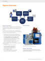
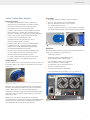
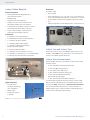
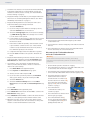
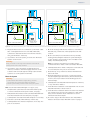
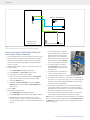
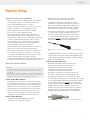
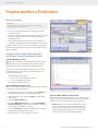
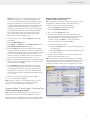
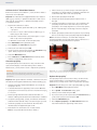
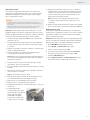
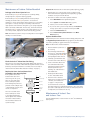
Isolera Dalton ™ Getting Started Guide Contents Isolera Dalton ™ Getting Started Guide CONTENTS 1 Intended Use and Safety 2 System Overview 5Installation 9 System Setup 10 Prepare and Run a Purification 15Maintenance 19Troubleshooting 20 Hints and Tips 21 General Information 2 Isolera Dalton Getting Started Guide | © Biotage 2015 ™ Intended Use and Safety Intended Use and Safety Intended Use Isolera Dalton System ™ Isolera Dalton System from Biotage is intended solely to detect, fractionate, and analyze chemical mixtures using flash chromatography and electrospray ionization mass spectrometry or light absorbance. ™ The system must be operated in a laboratory environment by trained professionals. The system is not designed to be operated in a potentially explosive atmosphere. It is the responsibility of the customer to classify (zone) their particular environment in order to verify that it meets the requirements of a “non-hazardous area” with regards to potentially explosive atmosphere. »» »» »» »» According to instructions available at www.biotage.com. According to instructions provided through dialogs appearing on the screen. According to instructions given by the technical support staff from Biotage. Isolera One and Isolera Four with an Isolera Spektra License ™ ™ Isolera Spektra is a software upgrade package that features a TLC-to-Step gradient calculator, λ-All detection, baseline correction, 3D absorbance spectrum for the whole detector range, and real-time PDA scanning. For more information, please refer to “Isolera Installation and Safety” (P/N 411828), “Isolera User Manual” (P/N 411829), and “Isolera Quick Guide” (P/N 411830). ™ Isolera Dalton System comprises the following separate units: ™ Safety Before performing any procedures in this document, please read and observe the safety requirements in the “Isolera Installation and Safety” document (P/N 411828) and “Isolera User Manual” (P/N 411829). Failure to follow those requirements may result in personal injury and/or equipment damage. ™ ™ Isolera Dalton Mass Detector ™ Isolera Dalton Nanolink ™ Isolera Dalton software ™ Isolera One or Isolera Four with an Isolera Spektra license ™ The Isolera Dalton software is designed to control Isolera Dalton Mass Detector and Isolera Dalton Nanolink. The software can be installed on Isolera One and Isolera Four systems with an Isolera Spektra license. ™ Within limits set by the system’s technical specification. ™ ™ Isolera One and Isolera Four are flash purification systems that allow the user to set up, control, and monitor purifications. According to the user documentation delivered with the system. Failure to follow those instructions and operate within the limits set by the technical specification may result in personal injury and/or equipment damage. »» »» »» »» Isolera Dalton Software ™ All operations must be performed: »» the order of 10 to 100 ml/min. These rates are too large for the microspray operation of Isolera Dalton Mass Detector, where the required flow rates are in the order of 1 µl/min. Incorporating an active splitter module between the flash purification system and the mass detector enables conversion to the correct flow for detection purposes, and allows for mass analysis through direct injection of samples. ™ Isolera Dalton Mass Detector ™ Isolera Dalton Mass Detector is a compact single quadrupole mass spectrometer built using micro-electromechanical systems (MEMS) technology. Isolera Dalton Mass Detector uses an electrospray ionization (ESI) source to produce ions, which can then be identified by their mass-to-charge ratio (m/z). Isolera Dalton Mass Detector allows you to analyze samples and automatically use the m/z ratio(s) of the identified substance(s) for flash purification. Isolera Dalton Nanolink ™ Isolera Dalton Nanolink is an integration module intended for use together with Isolera Dalton Mass Detector and Isolera One or Isolera Four. The flow rates of Isolera One/Four are in To guarantee safe and effective operation it is absolutely necessary to follow all of the safety precautions and instructions in the Isolera user documentation supplied by Biotage. Translated versions of the “Safety” chapter in the “Isolera Installation and Safety” document are available in the “Isolera Safety Translations” document (P/N 412861). ™ ™ Download Isolera User Documentation ™ To download the user documentation from the system, connect a USB memory device to the USB port located underneath the touch screen, press Help, and then press Export User Documentation. You can download the latest versions of the documents at www.biotage.com. If you have problems downloading, please contact your local Biotage representative. 1 System Overview Biotage DALTON System Overview Product Map Isolera™ Dalton Nanolink Isolera™ One or Four Isolera™ Dalton Mass Detector Isolera™ Dalton System Basic Functionality Isolera™ Dalton Software Setup Example © 2012 Biotage 1 A chemical sample, containing one or more components and dissolved in suitable solvent(s), can be injected into the system to identify characteristic m/z-ratio(s) for the substance(s) of interest. The detected m/z-ratio(s) can be used for identification and collection of specific components during a chromatography run. The purposes of the units in the system are: »» »» »» Isolera One/Four controls all units through the touch screen software and performs the flash chromatography. Isolera Dalton Nanolink is used as an active splitter for sampling a small portion from the larger flash chromatography flow into the mass detector. It also enables mass analysis via direct injection of samples. Isolera Dalton Mass Detector performs the detection and supplies information to the software when to collect and fractionate the sample. Isolera Dalton System can also be programmed to perform the following functions: »» »» »» »» 2 Generate user-defined elution gradients. Store and implement a large number of independent chromatographic methods. Control and collect fractions based on UV/visible light absorbance. Produce detailed, printable, and searchable reports on mass analysis and purification. Figure 1. Left top: Isolera Dalton Nanolink and tray. Left bottom: Isolera Dalton Mass Detector. Right: Isolera Four with an Isolera Spektra license. System Flow Scheme The left flow scheme on page 7 illustrates the flow when Isolera Dalton Mass Detector and Isolera Dalton Nanolink are connected to Isolera One/Four. Isolera Dalton Getting Started Guide | © Biotage 2015 ™ System Overview Isolera Dalton Mass Detector ™ Basic Components »» »» »» »» »» »» spraychip . The spraychip is a factory-calibrated disposable nanospray interface. A chemical sample, dissolved in suitable solvents, is introduced into the spraychip from Isolera Dalton Nanolink. ® Front Panel »» »» »» vac-chip . The vac-chip is a vacuum interface. It allows the mass detector to achieve the operating pressures required for analysis and it aligns the ions from the spraychip into the vacuum system through the vac-chip. ™ Ion optics. The ions generated from the spraychip enter the vac-chip and are focused into the ionchip using the ion optics. Vacuum system. This consists of a vacuum chamber coupled to two turbo-molecular pumps, which are supported by a small diaphragm pump. All pumps are integrated within the mass detector. ionchip . The ion-chip is a quadrupole that filters the ions according to their mass-to-charge (m/z) ratios and directs them into the detection system. ® Door with a safety interlock system to protect users from high voltages; see “Safety Interlock”below. Safety Interlock The mass detector has a safety interlock system to protect users from high voltages. This system is operated by the door in the front cover. A = Power switch for turning on the mass detector. B = Door. Only open the door for maintenance purposes when the system is not processing; see “Safety Interlock” above. C = High voltage port (max 1500 V, max 5 mA) for connecting the split flow interface (SFI) or the direct flow interface (DFI). B C A Figure 3. The front panel of Isolera Dalton Mass Detector. Rear Panel The following items at the rear panel are relevant when the mass detector is connected to Isolera One/Four: »» »» »» »» »» »» A = Nitrogen gas port. B = RS232 port for connecting the syringe pump (included in the calibration kit). C = 4 x USB ports. One is for connecting the mass detector software dongle. D = Ethernet port for connecting the mass detector to Isolera One/Four. E = Pump exhaust with sound silencer. F = Power switch and power inlet, 100 to 240 V AC ±10%. Figure 2. To protect the users, high voltages are disabled when the mass detector door is open. When the door is shut, the safety interlock is activated, high voltages can be applied, and the user is able to run the mass detector. When the door is open, the safety interlock is deactivated, and high voltages are disabled. A click will verify the position. The door will remain fixed in this position until pulled off its catch. With the door open and the safety interlock deactivated, replacement of the spraychip and vac-chip (see the “Maintenance” section on page 15) can be carried out with the mass detector in its installed location via access through the door. F B D C E A Figure 4. The rear panel of Isolera Dalton Mass Detector. 3 System Overview Isolera Dalton Nanolink Rear Panel ™ From left to right: Basic Components »» »» »» »» »» »» »» »» Active splitter with an integrated mass rate attenuation device. Makeup pump. Needle port for direct injection. Tubing to and from Isolera One/Four and tubing with a filter to the mass detector. »» »» Power switch. Power inlet (fused), 100 to 240 V AC ±10%. Isolera One/Four and Isolera Dalton Nanolink must be connected to a common ground, which is achieved by using the same power outlet. Fan. USB port (type B) for connecting the unit to Isolera One/Four. Solvent inlets for makeup solvents for neutral and for negative and positive ionization. Tray for safe assembly, solvent reservoir placement, and leakage collection. Front Panel »» »» »» »» »» »» »» »» »» A = Needle port for direct injection. B = External check valve for direct injection. C = Tubing to the active splitter. D = Tubing from the active splitter. E = Tubing (orange) from the makeup pump to the active splitter. Figure 7. The rear panel of Isolera Dalton Nanolink. F = Filter unit with microfilter. Isolera One and Isolera Four G = Tubing from Isolera One/Four, 140 cm. Please refer to the “Isolera User Manual” (P/N 411829) or the system’s online Help for more information on Isolera One and Isolera Four and their specific functions. ™ H = Tubing to Isolera One/Four, 120 cm with adapter. I = Tubing to the SFI inside the mass detector. ™ ™ Isolera User Documentation ™ E G H »» »» »» »» »» B A C D F I Figure 5. The front panel of Isolera Dalton Nanolink. Right Side Panel »» »» »» The following Isolera user documentation can be downloaded from the system: Solvent inlets: + (positive), N (neutral), and – (negative). Waste outlet. »» Isolera Installation and Safety, P/N 411828. ™ Isolera User Manual, P/N 411829. ™ Isolera Quick Guide, P/N 411830. ™ Isolera Safety Translations, P/N 412861. ™ Isolera Dalton Getting Started Guide (this document), P/N 413457. ™ Isolera Dalton System Care Guide, P/N UI320. ™ To download the documents from the system, connect a USB memory device to the USB port located underneath the touch screen, press Help, and then press Export User Documentation. You can download the latest versions of the documents at www.biotage.com. If you have problems downloading, please contact your local Biotage representative. Check valve release port (N/A). Figure 6. The right side panel of Isolera Dalton Nanolink. 4 Isolera Dalton Getting Started Guide | © Biotage 2015 ™ Installation Installation Warning Requirement Description • Isolera Dalton System shall be unpacked and installed by an authorized Biotage service engineer. • The total weight of the packages are approx. 50 kg (110 lbs) for Isolera Dalton Mass Detector, 20 kg (44 lbs) for Isolera Dalton Nanolink, and 42-46 kg (93-102 lbs) for Isolera One/Four. Use suitable lifting equipment when moving the packages. Follow generally accepted safety practices when handling and moving shipping boxes and containers. Weight Dalton Mass Detector: 32 kg (70.5 lbs) Dalton Nanolink: 10 kg (22.5 lbs) Isolera One/Four: 30-35 kg (66-77 lbs) depending on system configuration Power Line voltage: 100 to 240 V AC ±10% Line frequency: 50/60 Hz Isolera One/Four and Isolera Dalton Nanolink must be connected to a common ground, which is achieved by using the same power outlet. Max Power Consumed Dalton Mass Detector: 320 VA Dalton Nanolink: 130 VA Isolera One/Four: 200 VA Altitude Operation: up to 2000 m Temperature Operation: 15°C to 30°C Storage of Dalton Mass Detector: -10°C to +50°C Relative Humidity Operation: 40% to 80% non-condensing for temperatures up to 30°C Storage of Dalton Mass Detector: 0% to 80% non-condensing Pollution Degree Dalton Mass Detector: 2 Mass Detector Nitrogen Gas Pressure: 2 to 6 bar (29 to 87 psi) Purity: 99.9% Tubing: Only use Ø 1/4” OD tubing in stainless steel or PTFE to connect the mass detector to the gas supply. Five meters of PTFE tubing is supplied with the mass detector. If a fitting for conversion to Ø 1/4” OD is necessary, the fitting must be in stainless steel or PTFE. Fuses Dalton Nanolink: T2A-250 VAC (2 required) Isolera One/Four: T4A-250 VAC (2 required) Delivered Items Check the delivery against the shipping documentation to ensure that you have received everything. If any part of the order is missing, contact Biotage 1-Point Support . ® ™ Note: We strongly recommend that the boxes and packing materials are kept by the customer in case the system needs to be returned for service or moved to another location. Note: Before the system is shipped to the customer, its internal tubing is flushed with methanol (Isolera Dalton Mass Detector and Isolera Dalton Nanolink) and 80% ethanol in deionized water (Isolera One/Four), and then emptied. Site Requirements Before the system is installed by an authorized Biotage service engineer, the installation site should be prepared as follows: Requirement Description Location A laboratory fume hood with capacity to handle leakage of solvents used and provide and suitable airflow to prevent the build-up of flammable vapors. Note that if an internal system leakage occurs, the maximum leakage volume is determined by the size of the used solvent reservoirs and the flow rate is determined by the used method (max 200 ml/min). External fire protection should be installed according to local regulations for equipment operating unattended. Bench Space Dalton Mass Detector (W x D x H): 355 mm x 560 mm x 255 mm (14” x 22” x 10”) Dalton Nanolink (354 mm x 525 mm x 206 mm) must be placed on the tray on top of Dalton Mass Detector. Isolera One/Four (W* x D x H): 355/577 mm x 497 mm x 596 mm (14/22.7” x 19.6” x 23.5”) * The width is dependent on the number of collection trays (one/two). At least three centimeters (one inch) of space should be maintained between the rear panel of Isolera One/Four and other objects to allow proper ventilation. Move or Disconnect Isolera Dalton Mass Detector and Isolera Dalton Nanolink ™ ™ If you want to use Isolera One/Four without the mass detector or move the system within the laboratory or between laboratories in the same building, follow the applicable instructions below. Shut Down the System (Not for Daily Operation) Note: Only use this procedure to shut down the system when you want to 1) disconnect the mass detector to use Isolera One/ Four without it or move the system, 2) replace external tubing, or 3) clean the exterior of the system. 1. In the chemistry mode, select the Setup tab in the righthand panel. 2. Select the Mass Detector tab. 5 Installation 3. Clean the mass detector and Isolera Dalton Nanolink tubing by flushing it with neutral solvent (makeup solvent) and methanol or similar (Isolera solvent); see “Flush the Mass Detector Tubing” on page 15. 4. Empty the makeup solvent inlets by removing the inlets from their reservoirs and then priming them with air. See “Prime the Makeup Solvent Inlets” on page 10. 5. Empty the tubing between Isolera One/Four and Isolera Dalton Nanolink by performing an air flush: i. Select the Air Flush tab. ii. If you are using a system with four cartridge positions, select the Channel text box and select 1. iii. Select the Cartridge Type text box and select a cartridge, e.g. SNAP KP-Sil 10g. Note: The cartridge does not have to be mounted on the system. iv. For the pump to work properly, a small amount of solvent has to be used. Select the Solvent text box and select the desired solvent. v. Ensure that a sufficient quantity of the selected solvent is present in the solvent reservoir (1% of the air flush volume is used) and that the waste reservoir (waste 1) has sufficient capacity for the air flush. vi. Couple the cartridge’s inlet and outlet tubes together. vii.Press Start and wait for the system to finish the air flush. 6. Empty the internal tubing of the mass detector and Isolera Dalton Nanolink of liquid by pressing Start Flush at the Mass Detector tab. Wait for the system to finish the flush. 7. If you want to use Isolera One/Four without the mass detector, disable the automatic connection of the mass detector at system startup: i. Press Main Menu in the right-hand panel. ii. Press System. The Select User dialog opens. iii. Select your user name and press OK. iv. If your account is password-protected, the Password dialog opens. Enter your password and press OK. v. Select the Detector tab. vi. Select the Connect at Startup text box in the Mass Detector field and select No. The Restart Required dialog opens. vii.Press OK. 8. Press Main Menu in the right-hand panel. 9. Press Shut Down in main menu and then Yes to confirm. The Mass Detector dialog opens. 10.Press Shut Down and then Yes to confirm. This vents the mass detector to atmospheric pressure and then shuts it down. 11. When the message “It is now safe to turn off the system” appears on the screen, turn off Isolera One/Four. The power switch is located underneath the touch screen. 6 12.Turn off Isolera Dalton Nanolink using the power switch located at the rear. 13.Turn off the mass detector using the power switch located at the rear. 14.Disconnect the mass detector and Isolera Dalton Nanolink from Isolera One/Four as described below. Disconnect Isolera Dalton Mass Detector and Isolera Dalton Nanolink ™ ™ Warning Handle chemical and liquid waste according to the Safety Data Sheets and local/national guidelines on laboratory safety procedures. 1. Shut down the system as described on page 5. 2. Disconnect the mass detector, Isolera Dalton Nanolink, and Isolera One/Four from the mains supply. 3. Disconnect the tube connected between the Isolera flow cell and Isolera Dalton Nanolink from the flow cell’s upper port (A). 4. Disconnect the tube connected between the fraction collector and the extension connector (B) from the extension connector (B), and connect it to the flow cell’s upper port (A). See also the flow schemes on page 7. A 5. Disconnect the two communication cables; see scheme on page 8. B 6. Disconnect the mass detector from the nitrogen gas supply. 7. Disconnect the filter unit (C) from Isolera Dalton Nanolink by loosening the peek nut (D) and pulling the filter unit out. D C Isolera Dalton Getting Started Guide | © Biotage 2015 ™ Installation A B B A Figure 8. Flow schemes illustrating when Isolera Dalton Mass Detector and Isolera Dalton Nanolink are connected (left) and disconnected (right). 8. Empty the waste reservoirs connected to 1) the waste outlet tube on the right hand side of Isolera Dalton Nanolink, 2) the waste outlet tube at the front of the mass detector, and 3) the drain tube on the tray. 9. If you want to move the system, proceed to the “Move the System” section below. Warning: Keep your hands out of range of the collection arm while the homing routine runs in step 10 below. 10. If you want to use Isolera One/Four without the mass detector, connect it to the mains supply an turn it on. The collection arm moves through its homing routine and the system boots to the system’s main menu. Move the System Warning: • Isolera Dalton Mass Detector weighs 32 kg (70.5 lbs). Two persons are required when lifting the detector. • Follow regional safety practices when moving the system. Note: Isolera Dalton Nanolink weighs 10.2 kg (22.5 lbs). 1. Verify that the system has been shut down and the power cords disconnected from the power outlets; see page 5. 2. Verify that the mass detector and Isolera Dalton Nanolink have been disconnected from Isolera One/Four; see page 6. 3. Carefully lift Isolera Dalton Nanolink and place it on a trolley. 4. Place the Isolera Dalton Nanolink tray on the trolley. 6. Move the trolley(s) with the mass detector, Isolera Dalton Nanolink, tray, and the rest of the equipment to the new location. 7. Move Isolera One/Four to the new location by carefully reading and following the instructions in the “Moving an Isolera System” section in the “Isolera Installation and Safety” document (P/N 411828). ™ ™ Note: Do not turn Isolera One/Four on until you have connected the mass detector and Isolera Dalton Nanolink. 8. Carefully lift the mass detector and place it on the left side of Isolera One/Four. Two persons are needed. 9. Place the tray on top of the mass detector with the drain tube to the back. 10.Place the drain tube in a reservoir or on the Isolera leak tray (if using Biotage Leak Detector). Ensure the tube (and reservoir, if used) is visible from the working position to detect leakage. 11. Carefully lift Isolera Dalton Nanolink and place it on the tray on top of the mass detector. 12.Insert the waste outlet tube on the right hand side of Isolera Dalton Nanolink into a waste reservoir. 13.Insert the waste outlet tube at the front of the mass detector into a waste reservoir. Due to the vacuum, it is important that you never allow the waste outlet tube to become immersed in the waste liquid. 14.Proceed to step 5 in the “Reconnect Isolera Dalton Mass Detector and Isolera Dalton Nanolink” section on page 8. ™ ™ 5. Carefully lift the mass detector and place it on a trolley. Two persons are needed. 7 Installation Figure 9. Scheme for connecting and disconnecting the communication cables; a USB cable between Isolera One/Four and Isolera Dalton Nanolink and an Ethernet cable between Isolera One/Four and the mass detector. Reconnect Isolera Dalton Mass Detector and Isolera Dalton Nanolink ™ ™ 1. If reconnecting after a move of the system, proceed to step 5. 2. Empty the tube connected between the fraction collector and the flow cell using the air flush function; see step 5 in the “Shut Down the System (Not for Daily Operation)” section on page 5. 3. Enable the automatic connection of the mass detector at system startup: i. Press Main Menu in the right-hand panel. ii. Press System. The Select User dialog opens. iii. Select your user name and press OK. iv. If your account is password-protected, the Password dialog opens. Enter your password and press OK. v. Select the Detector tab. vi. Select the Connect at Startup text box in the Mass Detector field and select Yes. The Restart Required dialog opens. vii.Press OK. 4. Shut down Isolera One/Four: i. Press Main Menu in the right-hand panel. ii. Press Shut Down in main menu and then Yes to confirm. iii. When the message “It is now safe to turn off the system” appears on the screen, turn off Isolera One/ Four. The power switch is located underneath the touch screen. 8 5. Disconnect the tube connected between the fraction collector and the flow cell from the flow cell’s upper port (A), and connect it to the extension connector (B) on the tube connected to the To Isolera port on Isolera Dalton Nanolink. A B 6. Connect the tube connected to the From Isolera port on Isolera Dalton Nanolink to the flow cell’s upper port (A). 7. Connect the two communication cables; see the scheme above. C 8. Connect the filter unit (C) to Isolera Dalton Nanolink. 9. Connect the mass detector to a nitrogen gas supply with a pressure of 2 to 6 bar and a purity of 99.9%. Only use clean stainless steel or PTFE tubing and fittings for the nitrogen gas line to avoid contamination. 10.Connect the mass detector and Isolera Dalton Nanolink to the mains supply. Isolera One/Four and Isolera Dalton Nanolink must be connected to a common ground, which is achieved by using the same power outlet. 11. Turn on the system as described on page 10 and perform a mass detector function test as described on page 10. Note: In case of communication problems with the mass detector, try to resolve the problem and then press Test Communication at the Detector tab in the system mode to verify that the problem has been resolved. Isolera Dalton Getting Started Guide | © Biotage 2015 ™ System Setup System Setup General Use Recommendations »» Always use methanol of LC-MS grade and purified water »» »» »» »» »» »» for the makeup solvents on Isolera Dalton Nanolink. See “Load the Makeup Solvents” on page 10. »» »» Always use a clear and filtered (0.5 μm or less pore size) sample for analysis to avoid clogging the system. Always equilibrate the system and the cartridge before a run to avoid clogging the system. »» Always flush the mass detector and Isolera Dalton Nanolink tubing with neutral solvent (makeup solvent) and methanol or similar (Isolera solvent) after using DCM or before shutting the mass detector down or leaving it for more than 12 hours. This prevents e.g. blockages in the spraychip and vac-chip. See “Flush the Mass Detector Tubing” on page 15 for instructions. Never allow the waste outlet tube at the front of the mass detector to become immersed in the waste liquid. We recommend that the mass detector is only shut down for long-term non-usage and/or when it is to be moved, or to replace external tubing or clean the exterior of the system. See the shutdown procedure on page 5. Isolera Dalton Nanolink may be switched off when not in use, but must be started before Isolera One/Four is turned on. Verify that the waste outlet tube on the right hand side is inserted into a waste reservoir. Verify that the drain tube connected to the tray is inserted into a separate waste reservoir or placed on the Isolera leak tray (if using Biotage Leak Detector). Ensure that the drain tube (and reservoir, if used) is visible from the working position to detect leakage. Verify that any refitted tubes are assembled correctly. To ensure proper sealing for tubing connected at the front of Isolera Dalton Nanolink, it is important to orient the ferrule with the tapered portion of the ferrule facing away from the nut. Carefully place the ferrule inside the fitting before fastening the nut. Figure 10. Ferrule with the tapered portion facing away from the nut. »» Verify that the tubing is inserted correctly. Tubes should be inserted all the way and tube fittings/nuts tightened. Use caution when finger tightening fittings to prevent stripped threads or crushed ferrules. Isolera One and Isolera Four ™ Verify the System Setup »» Warning »» • Ensure that the power cords and any cables, hoses, and tubing connected to the system cannot come in contact with water or chemicals. • If a leakage is detected, immediately turn off the Isolera system, disconnect the power cord from the power outlet, and handle the leakage as described in the Leaks section on page 18. »» Isolera Dalton Mass Detector ™ »» »» Verify that the mass detector is connected to a nitrogen gas supply, with a pressure of 2 to 6 bar and a purity of 99.9%. Only use clean stainless steel or PTFE tubing and fittings for the nitrogen gas line to avoid contamination. Verify that the waste outlet tube at the front of the mass detector is inserted into a waste reservoir. Due to the vacuum, it is important that you never allow the waste outlet tube to become immersed in the waste liquid. ™ Verify that each waste outlet tube on the right hand side is inserted into a waste reservoir. Verify that the drain tube for the solvent tray (connected at the rear of the system) is inserted into a separate waste reservoir. Verify that Isolera One/Four is set up correctly; see the “Isolera Installation and Safety” (P/N 411828). ™ »» Verify that any refitted tubes are assembled correctly. If using flangeless tubing, please notice that proper sealing is only achieved with the ferrule oriented with the tapered portion of the ferrule facing toward the nut. The ferrule should be placed near the end of the tube. If using super flangeless tubing, ensure the ferrules are fitted onto the tube ends as described in the instructions supplied with the ferrules. Use caution when finger tightening fittings to prevent stripped threads or crushed ferrules. Isolera Dalton Nanolink ™ »» Verify that Isolera Dalton Nanolink is placed on the tray on top of the mass detector. Figure 11. Ferrule with the tapered portion facing toward the nut. 9 Prepare and Run a Purification Prepare and Run a Purification Start the System Warning: Keep your hands out of range of the collection arm while the homing routine runs in step 3 below. 1. Turn on Isolera Dalton Nanolink using the power switch located at the rear. 2. If the mass detector is not already turned on, turn it on using the power switch located at the rear and then the power switch at the front. 3. Wait at least 2 minutes and then turn on Isolera One/Four using the power switch located underneath the touch screen. The mass detector should be allowed to pump down adequate vacuum and to stabilize when turned on. The complete process takes 30 minutes. Prepare Isolera Dalton Mass Detector and Isolera Dalton Nanolink for a Run ™ Figure 12. At the Mass Detector tab, it is possible to prime the makeup solvent inlets and flush the mass detector and Isolera Dalton Nanolink tubing. ™ Load the Makeup Solvents Note: Always use methanol of LC-MS grade and purified water. Note: Ensure that no foreign matter (e.g. molecular sieve) is present in the reservoirs. If necessary, filter the solvents. Fill the three 1-liter bottles with the solvents to be used and connect them to the correct inlets on the right hand side of Isolera Dalton Nanolink: »» »» »» “Neutral”: methanol–water 9:1. “+”: 0.5% formic acid in methanol–water 9:1. “-”: 0.5% concentrated ammonium hydroxide in methanol–water 9:1. Prime the Makeup Solvent Inlets We recommend that a makeup solvent inlet is primed each time the makeup solvent is replenished. 1. Verify that a waste reservoir is connected to the WASTE port on the right hand side of Isolera Dalton Nanolink. 2. In the chemistry mode, select the Setup tab in the righthand panel. 3. Select the Mass Detector tab. 4. Select the Makeup Solvent text box in the Prime Makeup Pump Inlet Tubing field and select the makeup solvent to be primed (positive, negative, or neutral). 5. Press Start Prime. A status field and progress bar in the right-hand panel indicates the progress. 6. Repeat steps 4 to 5 for the other two solvents. 10 Figure 13. After installation, long-term storage, or for troubleshooting purposes, you are recommended to perform a mass detector function test. Perform a Mass Detector Function Test After installation, long-term storage, or for troubleshooting purposes, you are recommended to perform a mass detector function test. There are two function tests available: »» Baseline: Used to monitor the complete mass range 5o to 800 m/z and the status of the mass detector such as pressure, vacuum levels, and spray current. In this test, the background noise is observed and can be used to discover contamination peaks. Isolera Dalton Getting Started Guide | © Biotage 2015 ™ Prepare and Run a Purification »» Signal: Used to monitor a specific peak and mass range (the positive range is 50 to 80 m/z and the negative is 60 to 90 m/z) and the status of the mass detector such as pressure, vacuum levels, and spray current. In this test, a lower vac-chip voltage than what is normal during a run is applied, which allows methanol to create cluster ions visible at 65.1 m/z (positive mode) and 75.0 m/z (negative mode). Observe the intensity and abundance during the test; a well working system should have a strong and clear peak profile in both positive and negative mode. To perform a mass detector function test: 1. In the chemistry mode, select the Setup tab in the righthand panel. 2. Select the Mass Detector tab. 3. Press Signal... or Baseline... in the Function Test field. The Mass Detector Function Test dialog opens. 4. Press Positive and monitor the results. Results marked in green indicate proper function. If running a baseline test, verify that the signal and scans are stable and uninterrupted for the TIC and spectrum graphs. This may take up to 20 minutes to achieve. If running a signal test, verify that you have a strong and clear peak profile at 65.1 ± 0.7 m/z. 5. When you have collected enough data to determine whether the mass detector is working properly or not in the positive ionization mode, press Stop. 6. Press Negative and monitor the results. If running a baseline test, verify that the signal and scans are stable and uninterrupted for the TIC and spectrum graphs. This may take up to 20 minutes to achieve. If running a signal test, verify that you have a strong and clear peak profile at 75.0 ± 0.7 m/z. Assign Solvents to the Solvent Inlets on Isolera One or Isolera Four ™ ™ When a purification is run, the software references the solvent assignments to determine which solvent inlets that are connected to the solvents used in the method. 1. Select the Setup tab in the right-hand panel. 2. Select the Instrument Solvents tab. 3. Press one of the Solvent text boxes. 4. Select the solvent that the reservoir connected to the selected solvent inlet contains. The software comes with a preconfigured list of solvents and their parameters. To add a solvent, press New.... To edit a user defined solvent, select the solvent and press Edit.... 5. If solvent monitoring is enabled: i. Select the Capacity text box and enter the capacity of the solvent reservoir. ii. Select the Current text box and enter the current solvent level of the reservoir. 6. Repeat step 3 through 5 for all solvent inlets. All solvent inlets must be primed with solvent. Note: If monitoring of solvent and/or waste levels is enabled, you have to enter the capacities and current fluid levels for the solvent and waste reservoirs connected to Isolera One/Four each time you empty a waste reservoir or replenish a solvent. 7. When you have collected enough data, press Stop. 8. To close the dialog, press Close. Note: If the mass detector is not working properly, proceed to the “Troubleshooting” section on page 19 for further instructions or contact Biotage 1-Point Support. Prepare Isolera One or Isolera Four for a Run ™ ™ Load the Chromatography Solvents Note: Ensure that no foreign matter (e.g. molecular sieve) is present in the reservoirs. If necessary, filter the solvents. Fill the four reservoirs with the solvents to be used and connect them to the inlets on the right hand side of Isolera One/Four. At the Instrument Solvents tab, you assign the solvents used in the method to the solvent inlets on Isolera One or Isolera Four. 11 Prepare and Run a Purification Prime the Solvent Inlets on Isolera One or Isolera Four ™ ™ Prime the solvent inlets on Isolera One/Four to: »» »» remove any air bubbles from the pump and the solvent inlets by flushing them with solvents, or empty the solvent inlets of solvents used in the previous purification and fill them with new solvents. Warning: Never prime Isolera One/Four without a cartridge mounted on the system or without the cartridge’s inlet and outlet tubing coupled together. To avoid leakage, check all tubes and fittings before priming. Note: All solvent inlets on Isolera One/Four must be primed with solvent to achieve the specified pump performance. 1. Ensure that a sufficient quantity of the solvents you want to use is present in the solvent reservoirs and the waste reservoir(s) has/have sufficient capacity for the prime. 2. Select the Setup tab in the right-hand panel. 3. Ensure that the solvents are assigned accurately to the solvent inlets at the Instrument Solvents tab. 4. Select the Prime tab. 5. If you are using a system with four cartridge positions, select the Channel text box and select the cartridge position and waste reservoir to be used. 6. Select the Path text box and select the prime path. To only prime the solvent inlet(s), select Bypass. To also prime the cartridge channel, select one of the channel options. 7. If you selected the Without Cartridge path, couple the cartridge tubes together. 8. If you selected the With Cartridge path, select the Cartridge Type text box and select the cartridge type mounted on the system. 9. Select the Volume text box and enter the total prime volume. If you have filled a solvent inlet with a new solvent, we recommend that you prime with at least 40 ml of that solvent. If you also want to fill the liquid lines from the pump to the waste valve with the same solvent, we recommend that you prime with at least 100 ml. 10.Select the Flowrate text box and enter the flow rate. The maximum flow rate that can be used depends on: »» »» »» the cartridge type mounted on the system, if you selected the With Cartridge path in step 6 above, the maximum fill rate(s) defined for the used solvent(s) in the Data Administration mode, and the maximum dispense rate of the system (100 ml/min when using the mass detector, otherwise 200 ml/min). 11. Enter the percentage of each solvent connected to the system that shall be used in the prime. 12.To start priming, press Start. Set Up the Method For more information, you can at any time press Help to open the online help. 1. Select the Method tab in the right-hand panel. 2. To set up a new method, press New or Wizard.... The later option opens the method wizard, which will guide you step-by-step through the setup of a purification with a gradient including up to three steps using two solvents. When done, press Save to Editor in the wizard and proceed to step 7. 3. To open and edit an existing method, press Open and select the method in the dialog that opens. 4. Select the Gradient tab and create the desired gradient using the gradient table and/or the gradient graph. To show or hide the gradient table, press the Table button ( = the gradient table is shown). Note: Always add an equilibration step of at least 2 CV to avoid clogging of the mass detector and Isolera Dalton Nanolink. 5. Select the Parameters tab and select the solvents, cartridge type, and rack type to be used. 6. Select the Collection tab and specify the collection and fractionation settings to be used. To identify the m/z-ratio(s) for the substance(s) of interest, see the “Analyze the Sample” section on page 13. 7. If you want to save the method to be able to reuse it in the future, press Save As.... Note: You do not have to save a method to run it. 8. Proceed to the “Run the Purification” section on page 13. Prime the solvent inlets on Isolera One or Isolera Four at the Prime tab. 12 Isolera Dalton Getting Started Guide | © Biotage 2015 ™ Prepare and Run a Purification Analyze the Sample A chemical sample, containing one or more components and dissolved in suitable solvent(s), can be injected into the system to identify the m/z-ratio(s) for the substance(s) of interest. Note: Always use a clear and filtered (0.5 μm or less pore size) sample for analysis to avoid clogging. Required: The 250 µl syringe supplied with Isolera Dalton Nanolink (P/N 413710), sample, and methanol. 1. Prepare the sample: i. Make a diluted solution of your sample, approximately 1 mg/ml in methanol or another solvent. ii. Filter (0.5 μm or less pore size) your sample carefully to remove any particles that may clog the system. 2. Press Mass Analysis... at the Method tab. This opens the Mass Analysis Wizard. Follow the instructions appearing on the screen. 3. When the analysis is completed, copy the identified m/z-ratio(s) to the current method by pressing Save to Editor and Close in the last step of the wizard. The selected spectrogram will be included in the archive report. 8. Inject your sample into the cartridge inlet Luer fitting using a syringe. For ideal loading, do not apply high manual pressure with the syringe. Note: The sample is the undiluted form of the mixture that you may have analyzed to set up the method. Note: See the “Isolera User Manual” (P/N 411829) for cartridge loading capacity. ™ 9. When you have finished loading the sample, press Close and reconnect the cartridge inlet tubing to the cartridge’s inlet. 10.Start the gradient run by pressing Gradient . While the purification is running, one graph displays the programmed gradient and the other a dynamic chromatogram. The signals for the selected wavelength(s) and/or m/z-ratios are displayed in the chromatogram. An absorbance spectrum for the whole UV detector range can be viewed in the gradient view by pressing the Show λ button. The gradient is then displayed in the chromatogram. 11. When the run is finished, press Show Report to view and/or print a report. It is also possible to save the report as a PDF file on a connected USB memory device. Figure 14. The sample to be analyzed should be injected into the DIRECT INJECT port in a slow steady flow when prompted by the Mass Analysis Wizard. Run the Purification 1. Load the cartridge and collection rack(s) that you want to use. 2. Ensure that a sufficient quantity of the correct solvent is present in each solvent reservoir and that the waste reservoirs have the sufficient capacity for the run. 3. Press Run. The Run Parameters dialog opens. 4. If you are using a system with four cartridge positions, select the cartridge position to be used ( ). 5. Select the rack position(s) to be used ( ). Figure 15. While a purification is running, the programmed gradient and a dynamic chromatogram are displayed. The chromatogram can be magnified, dragged to the desired position, etc. Unload a Purification Warning Handle chemical and liquid waste according to the Safety Data Sheets and local/national guidelines on laboratory safety procedures. 6. Press Equilibrate . The system starts the equilibration and switches to the Status tab where the progress can be monitored. 1. If necessary, empty the cartridge of remaining solvents and pressure by using the air flush and purge features at the Setup tab. For instructions, press Help. 7. When the equilibration is finished, press Load Sample to enable sample injection. The Load Sample dialog opens. 2. If you are using a system with four cartridge positions and the system is processing, press Pause. 13 Prepare and Run a Purification 3. Unload the cartridge. To avoid leakage, plug the cartridge’s inlet and outlet fittings and couple the inlet and outlet tubes together. 4. Unload the rack(s) used by the run. Allocated racks are listed at the Allocated heading at the Status tab. 5. To clear the cartridge and rack positions in the software, press Remove. 6. If necessary, empty the waste reservoirs. 7. To resume processing of queued runs (see step 2 above), press Resume.... Access Result Records 2. Turn off Isolera One/Four: i. Press Main Menu in the right-hand panel. ii. Press Shut Down in main menu and then Yes to confirm. The Mass Detector dialog opens. iii. If you want to vent the mass detector to atmospheric pressure, press Vent. Otherwise, press Leave On. iv. When the message “It is now safe to turn off the system” appears on the screen, turn off Isolera One/Four. The power switch is located underneath the touch screen. 3. Turn off Isolera Dalton Nanolink using the power switch located at the rear. Purifications that are processed on the system are stored as individual records in the system’s database and can be found at the Results tab. For more information, refer to the “Isolera User Manual” or press Help to access the online help. ™ Figure 16. Two result reports are available for each purification: 1) an archive report with the selected spectrogram from the mass analysis (if available), purification details, a chromatogram, a 3D absorbance spectrum for the whole detector range, and TLC data (if entered), and 2) a fraction report. Shut Down the System We recommend that you keep the mass detector turned on for regular use. For longer periods of inactivity or storage, please follow the instructions in the “Shut Down the System (Not for Daily Operation)” section on page 5. The instructions below describe the procedure for shutting down after a working day. 1. If the mass detector is not planned to be used for 12 hours or more, always flush the mass detector and Isolera Dalton Nanolink tubing with neutral solvent (makeup solvent) and methanol or similar (Isolera solvent) to e.g. prevent blockages in the spraychip and vac-chip. For instructions, see the “Flush the Mass Detector Tubing” section on page 15. 14 Isolera Dalton Getting Started Guide | © Biotage 2015 ™ Maintenance Maintenance Please also refer to the “Isolera Dalton System Care Guide” document (P/N UI320). 3. Select the Mass Detector tab. Replace External Tubing 5. Select the Isolera Solvent (B) text box and select the Isolera solvent to be used. ™ Note: All tube types, dimensions, and lengths are essential for the performance of the system. Only replace tubes with the equivalent tubes supplied by Biotage. 1. Shut down the system as described on page 5. 4. Select the Makeup Solvent (A) text box in the Flush Tubing and Mass Detector field and select the makeup solvent to be used. 6. Press Start Flush and wait for the system to finish the flush. A status field and progress bar in the right-hand panel indicates the progress. 2. Replace damaged tubing. 3. Verify that tubes are assembled and inserted correctly; see the “Verify the System Setup” section on page 9. Sonicate Solvent Inlet Filters The solvent inlet filter is installed on the end of each solvent inlet line on Isolera Dalton Nanolink (P/N 413460SP, inlet lines and filters) and Isolera One/Four (P/N 412720SP, filters). These filters should be cleaned (sonicated) or replaced every 1000 hours of operation or every 12 months, whichever comes first. Clean the Exterior Warning Always disconnect the equipment from the mains supply before cleaning the exterior surfaces to avoid the risk of electric shock. Figure 17. At the Mass Detector tab, it is possible to flush the mass detector and Isolera Dalton Nanolink tubing. 1. Shut down the system as described on page 5. 2. Disconnect the power cords from the power outlets. 3. Clean the exterior surfaces of the mass detector and Isolera Dalton Nanolink using a soft and clean cloth. The cloth can be dry or lightly dampened with 10% aqueous isopropyl alcohol. After cleaning, wipe dry with a clean, lint-free cloth. 4. To clean the touch screen and the exterior of Isolera One/ Four, see the “Maintenance” section in the “Isolera User Manual” (P/N 411829). ™ Maintenance of Isolera Dalton Mass Detector ™ Flush the Mass Detector Tubing To prevent blockage of the mass detector when cancelling a run, we recommend that you empty the internal tubing of the previous solvent using the flush feature. 1. Verify that the waste reservoirs are in place; see the “Verify the System Setup” section on page 9. 2. In the chemistry mode, select the Setup tab in the righthand panel. Figure 18. At the Maintenance tab in the system mode, it is possible to calibrate the mass detector, clean or replace a vac-chip or spraychip , and reset the counter for the active splitter switches after replacing the rotor seal and stator face assembly. ™ ® 15 Maintenance Calibrate Isolera Dalton Mass Detector ™ If the mass accuracy is not within ± 0.7 m/z, the mass detector may need to be recalibrated. Required: The calibration kit supplied with the mass detector (P/N 413715), at least 500 µl filtered calibration solution (see step 1 below), and at least 500 µl filtered cleaning solution (1:1 methanol–water). 1. Prepare the calibration solution: i. Mix 50 ml of HPLC grade water with 50 ml of HPLC grade 2-propanol. ii. Dissolve 100 mg of sodium formate for HPLC (≥99.0% Fluka 17841) in the solution. iii. Filter the sodium formate solution through a 0.22 μm PTFE or nylon based syringe filter. iv. Mark the solution with one month expiry date. 7. Infuse at least 150 μl of the syringe solution through the spraychip at 10 μl/min until it is completely saturated. The solution will drip off the end of the spraychip. 8. Remove the spraychip from the DFI. 9. Gently blow dry the spraychip with compressed air or nitrogen. 10.Leave the spraychip for a few hours to dry completely. The spraychip should now be clean and ready for use. If the spraychip looks visually degraded or you have any queries, please contact Biotage 1-Point Support before using the spraychip. 11. Put the spraychip back into the mass detector by following the rest of the steps in the spraychip Replacement Wizard. ® Note: If an increased delay is observed when using the cleaned spraychip, clean it again. If the delay continues to be unacceptable, the spraychip must be replaced. 2. Press Main Menu in the right-hand panel. 3. Press System. The Select User dialog opens. 4. Select your user name and press OK. 5. If your account is password-protected, the Password dialog opens. Enter your password and press OK. 6. Select the Maintenance tab. 7. Press Calibrate in the Mass Detector field and follow the instructions appearing on the screen. Clean the spraychip ® The spraychip may become blocked or dirty over time. If the spray current displays a red value during a mass detector function test, you may need to clean or replace the spraychip. Warning Figure 19. The setup for cleaning the spraychip . The syringe pump, syringe, and direct flow interface are included in the calibration kit. ® Handle chemical and liquid waste according to the Safety Data Sheets and local/national guidelines on laboratory safety procedures. Replace the spraychip ® Required: HPLC grade methanol and water, a lint free tissue, and the calibration kit supplied with the mass detector (P/N 413715). The spraychip may become blocked or dirty over time. If the spray current displays a red value during a mass detector function test, you may need to clean or replace the spraychip. 1. Start the spraychip Replacement Wizard; see “Clean the spraychip ” above. Required: Powder-free gloves and a spraychip (P/N 413711SP). 2. Follow the instructions appearing on the screen. When the spraychip has been removed, clean it as described in steps 3 to 10 below. 2. Press System. The Select User dialog opens. ® ® 1. Press Main Menu in the right-hand panel. 3. Select your user name and press OK. 3. Fill the syringe included in the calibration kit with a 1:1 mixture of HPLC grade methanol and water with no additives. 4. If your account is password-protected, the Password dialog opens. Enter your password and press OK. 4. Set up the syringe pump, syringe, and direct flow interface (included in the calibration kit) as shown in Figure 19 below. 5. Select the Maintenance tab. 5. Screw the spraychip to be cleaned into the direct flow interface (DFI) and tighten the grub screw. 6. Press Replace spraychip in the Mass Detector field and follow the instructions appearing on the screen. ® 6. Place the DFI on a lint free tissue on a flat surface. Note: Do not put the DFI into the mass detector. 16 Isolera Dalton Getting Started Guide | © Biotage 2015 ™ Maintenance Clean the vac-chip ™ A vac-chip blockage may be indicated by 1) a low pressure reading of the ion guide (IG) vacuum or 2) a low mass detector signal when running a mass detector function test (signal). Clean or replace the vac-chip. Warning • Handle chemical and liquid waste according to the Safety Data Sheets and local/national guidelines on laboratory safety procedures. • Appropriate safety precautions must be taken when using a ultra sonic bath; see the manufacturer’s instructions. 13.Place the vac-chip in the oven at 75°C for 30 minutes to completely dry it. The vac-chip should now be clean and ready for use. If the vac-chip looks visually degraded or you have any queries, please contact Biotage 1-Point Support before using the vac-chip. Note: If an oven is not available, place the vac-chip on a lint free tissue and leave it for a few hours to dry completely. 14.Put the vac-chip back into the mass detector by following the rest of the steps in the vac-chip Replacement Wizard. ™ Replace the vac-chip ™ Required: A clean test tube with an inner diameter of 20 mm (supplied with the mass detector, P/N 413890SP), a pair of flat tweezers (supplied with the mass detector), an ultra-sonic bath, a petri dish, deionized water, methanol, and acetonitrile. A vac-chip blockage may be indicated by 1) a low pressure reading of the ion guide (IG) vacuum or 2) a low mass detector signal when running a mass detector function test (signal). Clean or replace the vac-chip. 1. Start the vac-chip Replacement Wizard; see “Replace the spraychip ” above. Required: Powder-free gloves and a vac-chip (P/N 413712SP). You also need the pair of tweezers, flat headed screwdriver, Allen key, and dust cover supplied with the mass detector. ™ ® 2. Follow the instructions appearing on the screen. When the vac-chip has been removed, clean it as described in steps 3 to 13 below. 3. Prepare a small ultrasonic bath in a fume hood. Fill the bath with room temperature water. 4. Hold the test tube horizontally and carefully place the vac-chip just inside the brim of the tube. Note: Always use a clean test tube with an inner diameter of 20 mm to avoid damaging the vac-chip. Three are supplied with the mass detector. 1. Press Main Menu in the right-hand panel. 2. Press System. The Select User dialog opens. 3. Select your user name and press OK. 4. If your account is password-protected, the Password dialog opens. Enter your password and press OK. 5. Select the Maintenance tab. 6. Press Replace vac-chip in the Mass Detector field and follow the instructions appearing on the screen. ™ 5. Slowly raise the test tube to allow the vac-chip to slowly slide down to the bottom of the tube. 6. Pour enough HPLC grade water into the test tube to cover the vac-chip. 7. Place the test tube in a suitable rack in the ultrasonic bath and sonicate for 10 minutes. Note: Do not heat the ultrasonic bath. 8. Remove the test tube from the bath and carefully pour out most of the liquid without removing the vac-chip. 9. Repeat steps 6 to 8 with HPLC grade acetonitrile. 10.Repeat steps 6 to 8 with HPLC grade methanol. 11. Gently tip the vac-chip into a shallow petri dish or onto a lint free tissue. 12.Carefully pick up the vac-chip using a pair of flat, plastic tweezers, by pinching either side of the larger metal SHIM, and gently blow dry the vac-chip with compressed air or nitrogen. 17 Maintenance Maintenance of Isolera Dalton Nanolink Required: Maintenance kit for the active splitter (P/N 413714SP). Leakage at the Direct Injection Port 1. Replace the rotor seal and stator face assembly using the maintenance kit supplied by Biotage (P/N 413714SP). Instructions are provided in the kit. ™ If the needle port (A) for direct injection is leaking during sample injection, replace it (P/N 413487SP). If the needle port (A) is leaking when the Isolera pump is running, the check valve (C) may need to be cleaned or replaced. To clean, unscrew the direct injection port assembly (see Figure 20 below) and inject a cleaning solution that is appropriate for the residues using the 250 µl syringe supplied with Isolera Dalton Nanolink. If necessary, unscrew and clean the check valve (C) using an ultra-sonic bath. If this does not solve the problem, replace the check valve (P/N 413480SP). Note: Ensure that system is not processing before removing the needle port or check valve. 2. Reset the counter for the active splitter switches: i. Press Main Menu in the right-hand panel. ii. Press System. The Select User dialog opens. iii. Select your user name and press OK. iv. If your account is password-protected, the Password dialog opens. Enter your password and press OK. v. Select the Maintenance tab. vi. Press Reset Active Splitter Switches in the Mass Detector field. Replace the Microfilter If high back pressure is detected in the makeup pump lines, and the High Makeup Flow Pressure dialog appears, the microfilter is probably partially clogged and needs to be replaced. C Note: The filter unit contains methanol. B 1. Ensure that the system is not processing. A ™ Figure 20. The direct injection port assembly: needle port (A), adapter (B), and check valve (C). Flush the Isolera Dalton Nanolink Tubing ™ Never leave Isolera Dalton Nanolink with DCM. Flush the mass detector and Isolera Dalton Nanolink tubing with neutral solvent (makeup solvent) and methanol or similar (Isolera solvent) as described in “Flush the Mass Detector Tubing” on page 15. Replace the Rotor Seal and Stator Face Assembly in the Active Splitter If the splitter valve leaks between the stator and stator ring or from a port, the rotor seal and stator face assembly may have been damaged by abrasive particles in the sample and/ or the makeup solvents, and need to be replaced. The rotor seal and stator face assembly also have to be replaced when the active splitter has switched more than 1 million times. The user will be alerted at system startup. 18 2. Disconnect the filter unit (A) from Isolera Dalton Nanolink by loosening the peek nut (B) and then pulling the filter unit out. B A 3. Carefully open the filter unit and remove the microfilter (C). 4. Insert a new microfilter and reassemble the filter unit, turning it clockwise. Ensure that the peek tube (D) is sticking out of the ferrule a few millimeters. C 5. Reattach the filter unit to Isolera Dalton Nanolink. ™ Body Shaft Assembly Rotor Seal Stator Ring Stator Face Assembly 6. Perform a mass detector function test for approximately D 1 minute; see instructions on page 10. The pressure should remain at a low level throughout the test, preferably between 2 and 5 bar. If the pressure is still high, the stator face assembly may need to be replaced (see instructions above). Stator Maintenance of Isolera One and Isolera Four ™ ™ See the “Maintenance” section in the “Isolera User Manual” (P/N 411829). ™ Stator Screws Isolera Dalton Getting Started Guide | © Biotage 2015 ™ Troubleshooting Troubleshooting Please also refer to the “Isolera Dalton System Care Guide” document (P/N UI320). ™ Leaks Warning Mass Detector Function Test If the system is malfunctioning, we recommend that you perform a mass detector function test as described on page 10. See below some actions for flow, pressure, and signal errors. Flow, Pressure, and Signal Errors If there is no spray current during a method run or mass detector function test, there could be an issue with the flow to the mass detector or a blockage in the spraychip. This may also pop up as an error dialog with the text “LOW SPRAY CURRENT” or “FAULT”. Verify that there is a flow to your mass detector by observing droplets from the waste outlet tube during a mass detector function test (signal or baseline). If droplets are observed but there is still no spray current, replace the spraychip as described on page 16. If the mass signal during a method run or a mass detector function test appears very unstable, it may indicate air in the tubing. Flush the mass detector and Isolera Dalton Nanolink tubing (see page 15) or prime the makeup solvent inlets (see page 10). If a low mass signal is observed during a mass detector function test (signal), this may indicate a blocked or partially blocked vac-chip. Clean or replace the vac-chip as described on page 16. The makeup flow pressure normally operates between 2.0 and 6.5 bar. If the makeup flow pressure is: »» »» Lower than 2 bar when the makeup pump is running, this may indicate leakage or malfunctioning check valves in Isolera Dalton Nanolink. Please contact Biotage 1-Point Support. Higher than 6.5 bar, this may indicate a microfilter blockage. Replace the microfilter as described in the High Makeup Flow Pressure dialog that appears or on page 18. If this does not solve the problem, the stator face assembly may need to be replaced (see page 18). Do not wipe away any excess solvent from the cartridge surface as the process of wiping can generate additional static charge. If a leakage is detected, immediately turn off the Isolera system and disconnect the power cord from the power outlet. If the leakage is clearly located to the connections or the external tubing of Isolera Dalton Nanolink, replace the relevant tubing. Only use spare parts and accessories from Biotage. If the needle port for direct injection is leaking during sample injection, replace it (P/N 413487SP). If the needle port for direct injection is leaking when the Isolera pump is running, the check valve (P/N 413480SP) may need to be cleaned or replaced. See “Leakage at the Direct Injection Port” on page 18. If leakage is detected on the Isolera Dalton Nanolink tray, or via the drain tube connected to the tray, then the leak is likely located inside Isolera Dalton Nanolink. Please contact Biotage 1-Point Support. If the splitter valve leaks between the stator and stator ring (see image on page 18) or from a port, the rotor seal and stator face assembly may have been damaged by abrasive particles in the sample and/or the makeup solvents. Replace the rotor seal and stator face assembly using the maintenance kit supplied by Biotage (P/N 413714SP). Instructions are provided in the kit. When done, reset the counter for active splitter switches as described on page 18. If the leakage is detected on Isolera One/Four, see the “Leaks” section in the “Isolera User Manual” (P/N 411829). ™ Troubleshooting of Isolera One and Isolera Four ™ ™ See the “Troubleshooting” section in the “Isolera User Manual” (P/N 411829). ™ If the mass detector vacuum pressure is outside the specifications (see below), this may indicate a vac-chip blockage or vacuum leakage in the mass detector. Clean or replace the vac-chip as described on page 16 or contact Biotage 1-Point Support. »» »» -2 IG (ion guide) vacuum: approx. 1 x 10 Torr in -3 running mode and 1 x 10 Torr in standby mode. -4 AQ (analytical quadrupole) vacuum: < 5 x 10 Torr. This value will decrease the longer the system is left under vacuum. 19 Hints and Tips Hints and Tips Some Commonly Quoted Volatile Additives and Buffers Recommended Volatile Additive or Buffer Empirical Formula pKa Formic acid HCOOH 3.8 Ammonium hydroxide NH4OH 9.2 Commonly Observed Adduct Ions From Buffer Additives (at 50 V) 20 Mass of Adduct Ion Source of Adduct Ion Formula of Adduct Ion M+59 Acetic acid [M+CH3COO]- M+35/37 Chlorinated solvent [M+Cl]- M+18 Ammonia [M+NH4]+ M+23 Sodium salt [M+Na]+ M+39 Potassium salt [M+K]+ M+42 Acetonitrile [M+CH3CNH]+ M+33 Methanol [M+CH3OH2]+ M+19 Water [M+H3O]+ M+45 Formic acid [M+HCOO]- Isolera Dalton Getting Started Guide | © Biotage 2015 ™ General Information General Information Consumables and Accessories Only genuine Biotage consumables and accessories must be used in the system. To order consumables and accessories, see contact information on the back of this document or visit our website www.biotage.com. Accessories that may be necessary for the “Maintenance” section in this document are listed below. Manufacturers Microsaic Systems plc for Biotage Sweden AB (Isolera Dalton Mass Detector) PartnerTech Åtvidaberg AB for Biotage Sweden AB (Isolera One, Isolera Four, and Isolera Dalton Nanolink) Part no. Description Contact Us 413460SP Solvent inlet tubing with inlet filters for Isolera Dalton Nanolink, qty 3 414632SP Split flow interface (SFI) with tubing, qty 1 413875SP External tubing kit for Isolera Dalton Nanolink, qty 1 of each tube. 413460SP and 413741SP (see above) is not included Biotage Sweden AB Box 8 SE-751 03 Uppsala SWEDEN 413480SP External check valve for the direct injection port, qty 2 413483SP Microfilter holder with filter, qty 1 413484SP Microfilter, qty 5 413487SP Needle port for direct injection, qty 2 413710SP 250 µl gastight syringe, qty 1 413711SP spraychip, qty 1 413712SP vac-chip, qty 1 413714SP Maintenance kit for the active splitter, qty 3 413715 Calibration kit for Isolera Dalton Mass Detector, qty 1 413743SP Direct flow interface (DFI), qty 1 413890SP Tubes, 20 x 150 mm, for cleaning the vac-chip, qty 3 Visiting address: Vimpelgatan 5 Phone: +46 18 56 59 00 Fax: +46 18 59 19 22 E-mail: [email protected] Website: www.biotage.com Please contact your local Biotage representative. See contact information on the back of this document or visit our website www.biotage.com. 21 Title (truncated if necessary) | Page 22 Your Complete Partner for Effective Chemistry Biotage is a worldwide supplier of instruments and accessories designed to facilitate the work of laboratory chemists. With our deep knowledge of the industry, academic contacts and in-house R&D teams, we can deliver the best solutions to your challenges. We take great pride in our flexibility and ability to meet our customer’s individual needs. With strong foundations in both analytical and organic chemistry, we can offer the widest range of solutions available on the market. EUROPE Main Office: +46 18 565900 Toll Free: +800 18 565710 Fax: +46 18 591922 Order Tel: +46 18 565710 Order Fax: +46 18 565705 [email protected] Support Tel: +46 18 56 59 11 Support Fax: + 46 18 56 57 11 [email protected] NORTH & LATIN AMERICA Main Office: +1 704 654 4900 Toll Free: +1 800 446 4752 Fax: +1 704 654 4917 Order Tel: +1 704 654 4900 Order Fax: +1 434 296 8217 [email protected] Support Tel: +1 800 446 4752 Outside US: +1 704 654 4900 [email protected] JAPAN Tel: +81 3 5627 3123 Fax: +81 3 5627 3121 [email protected] [email protected] Part Number: 413457-E © 2015 Biotage. All rights reserved. No material may be reproduced or published without the written permission of Biotage. Information in this document is subject to change without notice and does not represent any commitment from Biotage. E&OE. A list of all trademarks owned by Biotage AB are available at www.biotage.com/legal. Other product and company names mentioned herein may be trademarks or registered trademarks and/or service marks of their respective owners, and are used only for explanation and to the owners’ benefit, without intent to infringe. © Biotage 2015 CHINA Tel: +86 21 2898 6655 Fax: +86 21 2898 6153 [email protected] [email protected] To locate a distributor, please visit our website at www.biotage.com