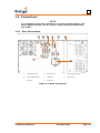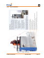
1
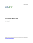
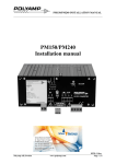
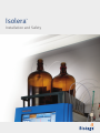
Isolera
™
Installation and Safety
1
Safety and Document Conventions
Isolera™ systems shall be unpacked and installed by an authorized Biotage service engineer. Please read this
manual carefully before operating the Isolera system. All information is believed to be complete and accurate at
the time of publication, but is subject to change.
The Isolera system should only be operated and maintained by trained individuals. Please read the “Isolera™
User Manual” (P/N 411829) carefully before working with the system. To guarantee safe and effective operation
it is absolutely necessary to follow all of the instructions in the “Isolera™ User Manual”.
Pay close attention to text with a NOTE or WARNING heading:
NOTE
Note text appears in the manual to provide additional or crucial information about
the current topic. It may indicate a situation in which the system may not perform
as expected unless specific guidelines are followed.
WARNING
The Warning note indicates a hazard that could result in serious injury to the user
and/or damage to the equipment unless good laboratory practices and/or
manufacturer's guidelines are followed.
Warranty and Liability
See the “Biotage Terms & Conditions of Sale” document at www.biotage.com.
Software License Agreement
Biotage Sweden AB licenses the Isolera software to you only upon the acceptance of all of the terms and
conditions in the software license agreement. By using the software, you consent to be bound by and are
becoming a party to that agreement.
If you do not agree to the terms of the software license agreement, the software may be returned for full
refund, terminating the license as described in the agreement.
To read the software license agreement, either request a copy from your local Biotage representative before the
installation or read it on your Isolera system:
1. Turn on the system using the power switch located underneath the touch screen.
2. Once the main menu appears, press About and then Show Licenses.
Download Isolera™ User Documentation
The following Isolera user documentation can be downloaded from the system:
• Isolera™ Installation and Safety (this publication), P/N 411828
• Isolera™ User Manual, P/N 411829
• Isolera™ Quick Guide, P/N 411830
• Isolera™ Safety Translations, P/N 412861
• Isolera™ Dalton Getting Started Guide, P/N 413457
• Isolera™ Dalton System Care Guide, P/N UI320
To download the user documentation from the system, connect a USB memory device to the USB port located
underneath the touch screen, press Help, and then press Export User Documentation.
You can download the latest versions of the documents at www.biotage.com. If you have problems
downloading, please contact your local Biotage representative.
Page ii
Table of Contents
1: Installation - - - - - - - - - - - - Delivered Items - - - - - - Site Requirements - - - - - Moving an Isolera™ System - Connections- - - - - - - - Rear Connections - - - Tube Connections - - - -
--- - - - - - -
--- - - - - - -
--- - - - - - -
---- - - - - - - - - - - - -
--- - - - - - -
---- - - - - - - - - - - - -
--- - - - - - -
--- - - - - - -
-
--- - - - - - -
--- - - - - - -
-
1-1
1-2
1-2
1-3
1-6
1-6
1-7
2: Safety - - - - - - - - - - - - - - - - - - - - - - Overview - - - - - - - - - - - - - - Intended Use - - - - - - - - - - - - Education, Training, and Competence - Static Electricity - - - - - - - - - - - Download User Documentation - - - - Warranty and Liability - - - - - - - - Service - - - - - - - - - - - - - - - Safety Requirements - - - - - - - - - Installation - - - - - - - - - - - Operation - - - - - - - - - - - Power Supply and Fuses - - - - - Solvents and Waste - - - - - - - Lab Safety Procedures - - - - - - Collection Arm - - - - - - - - - Ultraviolet Light - - - - - - - - - In Case of Leakage and Maintenance External Tubing and Fittings - - - Labels Used on the System - - - - - - WEEE Compliance Statement - - - - - Safely Starting Up and Shutting Down - Start Up the System - - - - - - - Pause and Resume a Purification RunEnd or Abort a Purification Run - - Orderly System Shutdown Procedure System Components - - - - - - - - - -
--- - - - - - - - - - - - - - - - - - - - - - - - - -
---- - - - - - - - - - - - - - - - - - - - - - - - - - - - - - - - - - - - - - - - - - - - - - - - - - -
--- - - - - - - - - - - - - - - - - - - - - - - - - -
---- - - - - - - - - - - - - - - - - - - - - - - - - - - - - - - - - - - - - - - - - - - - - - - - - - -
--- - - - - - - - - - - - - - - - - - - - - - - - - -
--- - - - - - - - - - - - - - - - - - - - - - - - - -
-
--- - - - - - - - - - - - - - - - - - - - - - - - - -
--- - - - - - - - - - - - - - - - - - - - - - - - - -
-
2-1
2-1
2-1
2-1
2-2
2-2
2-3
2-3
2-3
2-3
2-4
2-4
2-4
2-4
2-4
2-4
2-4
2-5
2-5
2-6
2-6
2-6
2-6
2-6
2-7
2-8
3: Contact Information - - - - - - Manufacturer - - - - - - - Biotage Sweden AB - - - - Sales Offices and Distributors Technical Support - - - - - -
--- - - - -
---- - - - - - - - -
--- - - - -
---- - - - - - - - -
--- - - - -
--- - - - -
-
--- - - - -
--- - - - -
-
3-1
3-1
3-1
3-1
3-1
--- - - - -
-
-
--- - - - -
Page iii
Chapter
1
Installation
WARNING
The Isolera™ system shall be unpacked and installed by an authorized
Biotage service engineer.
If an internal system leakage occurs, liquids are drained through drain
ports underneath the system. The Isolera system must therefore be
operated in a well-ventilated fume hood that has the capacity to handle
leakage of potentially flammable liquids and that meets the requirements
of a “non-hazardous area” with regards to potentially explosive
atmosphere. If using an Isolera™ LS Funnel Rack Kit, a walk-in fume hood
must be used. Note that the maximum leakage volume is determined by
the size of the used solvent reservoirs and that the flow rate is determined
by the used method (the flow rate can be set to a maximum of 100 ml/min
when using an Isolera™ Prime system, 200 ml/min when using an
Isolera™ One, Isolera™ Four, or Isolera™ Dalton System, and 500 ml/min
when using an Isolera LS system).
You must observe all the safety requirements on page 2-3 and 2-5 when
operating the Isolera system. Failure to use the system in a manner specified
by Biotage may result in personal injury and/or equipment damage. If the
system has been damaged or does not function properly, shut it down and
contact Biotage® 1-Point Support™ immediately (www.biotage.com).
The total weight of the package including the Isolera system is 42-46 kg
(93-102 lbs) depending on the system configuration. The weight of the
Isolera™ Dalton Mass Detector and Isolera™ Dalton Nanolink packages
(if ordered) are 50 kg (110 lbs) and 20 kg (44 lbs), respectively. Use
suitable lifting equipment when moving the package. Follow generally
accepted safety practices when handling and moving shipping boxes and
containers.
The Isolera system weighs 30-35 kg (66-77 lbs) depending on the system
configuration. Isolera Dalton Mass Detector and Isolera Dalton Nanolink
(if ordered) weighs 32 kg (70.5 lbs) and 10 kg (22.5 lbs), respectively.
Two persons are required when lifting the systems.
NOTE
It is strongly recommended that Biotage® Leak Detector is used with the
Isolera system. Biotage Leak Detector is optional on Isolera Prime, Isolera
One, and Isolera Four and standard on Isolera LS.
411828-M, Installation
December 2014
Page 1-1
1
1.1 Delivered Items
NOTE
We recommend that the boxes and packing materials are kept by the
customer in case the system needs to be returned for service or moved to
another location.
The system’s internal tubing is flushed with 80% ethanol in deionized
water and then emptied before the system is shipped to the customer.
Isolera Dalton Mass Detector and Isolera Dalton Nanolink (if ordered) are
flushed with methanol.
Check the delivery against the shipping documentation to ensure that you have received everything.
If any part of the order is missing or damaged, contact Biotage 1-Point Support (see page 3-1).
1.2 Site Requirements
NOTE
For the site requirements for Isolera Dalton System, see the “Isolera™
Dalton Getting Started Guide”, P/N 413457.
Before the system is installed by an authorized Biotage service engineer, the installation site should
be prepared as follows:
Environment
Location: A laboratory fume hood with capacity to handle leakage of solvents and provide
suitable airflow to prevent the build-up of flammable vapors. If using an Isolera LS Funnel
Rack Kit, a walk-in fume hood must be used.
Temperature: 15°C to 32°C (59°F to 89.6°F)
Humidity: 20% to 95% at room temperature
External fire protection should be installed according to local regulations for equipment
operating unattended.
Dimensions
Width: 355 mm (14") or, when using a system with two collection trays, 577 mm (22.7");
Depth: 497 mm (19.6");
Height: 596 mm (23.5")
At least three centimeters (one inch) of space should be maintained between the system’s
rear panel and other objects to allow proper ventilation.
If using an Isolera LS Funnel Rack Kit, the cart dimensions (W x D x H) are:
960 mm (37.8") x 660 mm (26.0") x 1060 mm (41.7").
Weights
30-35 kg (66-77 lbs) depending on system configuration
If using an Isolera LS Funnel Rack Kit, the cart (excluding bottles) weighs approximately
40 kg (88 lbs).
Power
Input voltage: 100-240 VAC, 50/60 Hz
Maximum power consumed: 200 VA
411828-M, Installation
December 2014
Page 1-2
1
1.3 Moving an Isolera™ System
NOTE
Should you need to move the system within the laboratory or between
laboratories in the same building, follow the instructions below.
If you are using Isolera Dalton System, see the “Isolera™ Dalton Getting
Started Guide” (P/N 413457) for instructions on how to shut down the
system, and disconnect, move and reconnect Isolera Dalton Mass Detector
and Isolera Dalton Nanolink.
1. When the system is not processing, shut it down as described on page 2-7.
2. Unplug the power cord from the power outlet.
3. Disconnect any external equipment connected to the LEAK DET., ETHERNET, VGA, MOUSE
(only available on some systems), and/or USB ports at the rear of the system.
4. Disconnect the drain tube at the rear of the system; see Figure 1-4 on page 1-6.
5. Disconnect the waste outlet tubing; see “Tube Connections” on page 1-7.
6. Remove the racks and solvent bottles.
7. Carefully lift the Isolera system by the base plate and place it on a trolley. Two persons are
needed.
8. Move the trolley and the rest of the equipment to the new location.
9. If using Biotage Leak Detector:
a. Place the leak tray in a well-ventilated fume hood or an equivalent enclosure that meets
the site and safety requirements. Position the tray so that the leak detector is in the back
right corner and the Isolera system will be in a position that allows access to the right side
and the rear of the system; see Figure 1-1 below.
b. Carefully lift the Isolera system by the base plate and place it on the leak tray. Two
persons are needed.
c. Connect the leak detector cable to the LEAK DET. port at the rear of the Isolera system.
Leak detector
Leak tray
Figure 1-1. Isolera One with Leak Detector
10. If not using Biotage Leak Detector, carefully lift the Isolera system by the base plate and place
it in a well-ventilated fume hood or an equivalent enclosure that meets the site and safety
requirements. Place it in a position that allows access to the right side and the rear of the
system. Two persons are needed.
11. Connect the drain tube to the Drain port at the rear of the system; see Figure 1-4 on page 1-6.
Insert the other end into a separate waste reservoir.
12. If you want to connect the system to your network, connect a shielded category 5 TP cable to
the ETHERNET port.
13. If you want to connect an external screen, connect it to the VGA port at the rear of the system.
411828-M, Installation
December 2014
Page 1-3
1
14. If you want to connect a mouse, connect it to one of the USB ports at the rear of the system.
Note that some versions of the system have a MOUSE port and only one USB port.
15. If you want to connect a USB printer, connect it to one of the USB ports at the rear of the
system.
16. If you want to connect an external detector to the system, see the “Change Detector Settings”
section in the “Isolera™ User Manual” (P/N 411829).
17. Connect the system to a properly grounded (earthed) power outlet with the correct mains
voltage and frequency (see the product label at the rear of the system) using the supplied
power cord.
18. Ensure the cartridge holder(s) is/are in preferred position(s) at the right side of the system;
see Figure 1-2 below.
Figure 1-2. Mount the Supplied Cartridge Holder(s)
19. If the system is equipped with an AIR port at the right side of the system, ensure that the air
filter is connected. If not, connect it (see Figure 1-3 below).
Figure 1-3. Connect the Air Filter
20. Connect the waste outlet tubing. Ensure that all tubing is connected according to Figure 1-5 on
page 1-7. Use caution when tightening fittings to prevent stripped threads or crushed ferrules.
NOTE
Ensure that the tubes are assembled correctly. If the system has
flangeless tubing, please notice that proper sealing will not occur unless
the ferrule is oriented as shown below, with the tapered portion of the
411828-M, Installation
December 2014
Page 1-4
1
ferrule facing toward the nut. The ferrule should be placed near the end of
the tubing as shown below.
21. Carefully slide the system into a position where the operator can access the touch screen,
cartridge holder(s), and collection area. At least three centimeters (one inch) of space should
be maintained between the system’s rear panel and other objects to allow proper ventilation.
22. Level the system by adjusting the height of the four feet.
WARNING
To avoid possible injury and equipment damage, keep your hands out of
range of the collection arm while the homing routine runs in step 23 below.
23. Turn on the system. The power switch is located underneath the touch screen.
24. To change system settings (change date and time for the system, enable Biotage Leak Detector
(enabled by default on Isolera LS systems), enable an external detector, turn on the mouse
pointer, configure a network connection, set up a printer with postscript support, etc), log into
the System mode and refer to the instructions available in the online help:
a. In the main menu, press System.The Select User dialog opens.
b. Select a system owner account and press OK. The Password dialog opens.
c. Enter the password and press OK. If using the system owner account that was created at
installation, enter the password "1234".
d. To open the online help, press Help in the right-hand panel.
25. To set up user accounts, log into the Data Administration mode and refer to the instructions
available in the online help:
a. In the main menu, press Data Administration.The Select User dialog opens.
b. Select a system owner account and press OK. The Password dialog opens.
c. Enter the password and press OK.
d. To open the online help, press Help in the right-hand panel.
26. Once the system is operational, check all tubes and connections for leaks using the prime
function (see the “Prime the System” section in the “Isolera™ User Manual”, P/N 411829).
Prime with water or another suitable solvent. If leakage is observed, pause the system (press
the Pause button in the right-hand panel) and check for loose fittings or damaged tubing. To
resume the prime, press Resume in the right-hand panel.
411828-M, Installation
December 2014
Page 1-5
1
1.4 Connections
NOTE
For information about the connections on Isolera Dalton Detector and
Isolera Dalton Nanolink, see the “Isolera™ Dalton Getting Started Guide”,
P/N 413457.
1.4.1
Rear Connections
A
B
C
D
E
F
G
H
A
Leak Detector Port
D
Ethernet Port
G
Only Used for Service
B
External Detector Port
E
USB Ports
H
Power Inlet
C
VGA Port
F
Drain Port
Figure 1-4. Rear Connections
411828-M, Installation
December 2014
Page 1-6
1
1.4.2
Tube Connections
Figure 1-5. Tube Connections
411828-M, Installation
December 2014
Page 1-7
Chapter
2
Safety
2.1 Overview
The Isolera system must be operated in a fume hood that has the capacity to handle leakage of
solvents and provide suitable airflow to prevent the build-up of flammable vapors. The optimum
operating temperature range for the Isolera system is 15°C to 32°C (59°F to 90°F). At least three
centimeters (one inch) of space should be maintained between the system’s rear panel and other
objects to allow proper ventilation. Should a leakage or solvent spill occur, your laboratory must
have local regulated processes in place to deal with these incidents in order to prevent the
possibility of a fire or explosion hazard.
2.2 Intended Use
All Isolera systems from Biotage are intended solely to detect, fractionate, and analyze chemical
mixtures using flash chromatography and electrospray ionization mass spectrometry and/or light
absorbance.
The system must be operated in a laboratory environment by trained professionals. The system is
not designed to be operated in a potentially explosive atmosphere. It is the responsibility of the
customer to classify (zone) their particular environment in order to verify that it meets the
requirements of a “non-hazardous area” with regards to potentially explosive atmosphere.
All operations must be performed:
• According to the user documentation delivered with the system.
• According to instructions available at www.biotage.com.
• According to instructions provided through dialogs appearing on the screen.
• According to instructions given by the technical support staff from Biotage.
• Within limits set by the system’s technical specification.
Failure to follow those instructions and operate within the limits set by the technical specification
may result in personal injury and/or equipment damage.
2.3 Education, Training, and Competence
It is your responsibility to provide all applicable health and safety regulations to your personnel.
You must also ensure that all personnel involved in the operation and maintenance of the system
fulfill the following criteria:
• Have the necessary education, training, and competence required for the intended use of the
system.
• Observe general and specific safety regulations for the use of the system and its accessories
and consumables at all times, in order to reduce the risk of personal injury, fire, and explosion.
411828-M, Safety
December 2014
Page 2-1
2
2.4 Static Electricity
When using Isolera flash purification systems with Biotage flash cartridges or any other commercial
or home-made cartridge, care must be taken to avoid the consequences of static electricity buildup. This is particularly important when using the systems with flammable, non-conducting solvents
operating under high-flow conditions. Static electricity can be generated as non-polar liquids flow
through cartridges, tubing, pipes, valves, and filters during chromatographic operations. It can
also be brought to the operating environment by human bodies that have accumulated
static charge; please follow your local regulations that apply to static electricity hazards.
There are a number of simple steps that should be taken as important safety precautions:
• If you are not using the integrated Isolera fraction collector (using the Bypass Tray software
feature), always collect solvents in a container that is grounded to earth to avoid build-up of
static charge in the container. Ensure that the solvent tubing exit is positioned below the
solvent surface in the collection container.
• When operating the Isolera system, especially when using high flow rates, wear anti-static
clothing and shoes, or stand on an anti-static floor mat.
• If you cannot take the usual anti-static measures, touch a grounded metal object before
approaching and handling the cartridge or Isolera system to discharge any static electricity
that may have accumulated in your body. Grounded water pipes are particularly useful for
static electricity discharge.
• Do not exceed recommended flow rates for flash cartridges (this information can be found in
the flash cartridge documentation) nor allow flow at higher rates than specified through any
Samplet®, dry load vessels, or pre-cartridges that you may be using. This can increase the
risk of static build-up.
• Ensure that the presence of air bubbles in the flow lines is minimized since these can increase
electrostatic charge by orders of magnitude.
• Static effects are most evident in low humidity situations. Maintaining humidity above 65%
can be helpful as a preventive measure.
• In the event of solvent leaks, immediately switch off the system and disconnect the power
cord(s). Do not wipe solvent away whilst the system is operating. In the event of leakage
from a cartridge, immediately switch off the system, disconnect the power cord(s) and allow
all solvent vapor to dissipate before removing the cartridge. Do not wipe away any excess
solvent from the cartridge surface as the process of wiping can generate additional
static charge.
• Read and follow your local static discharge codes of practice and available EU or US
recommended procedures for the avoidance of hazards due to static electricity.
To guarantee safe and effective operation, it is absolutely necessary to follow all of the safety
precautions and instructions in the user documentation supplied by Biotage.
2.5 Download User Documentation
The following Isolera user documentation can be downloaded from the system:
• Isolera™ Installation and Safety, P/N 411828
• Isolera™ User Manual, P/N 411829
• Isolera™ Quick Guide, P/N 411830
• Isolera™ Safety Translations, P/N 412861
• Isolera™ Dalton Getting Started Guide, P/N 413457
• Isolera™ Dalton System Care Guide, P/N UI320
To download the documents listed above, connect a USB memory device to the USB port located
underneath the touch screen, press Help, and then press Export User Documentation.
411828-M, Safety
December 2014
Page 2-2
2
2.6 Warranty and Liability
See the “Biotage Terms & Conditions of Sale” document at www.biotage.com.
2.7 Service
All service or adjustments must be performed by an authorized Biotage service engineer. Before
handing over the system for service, it should be emptied of liquid and cleaned from harmful
residues.
It is the responsibility of the customer to inform Biotage 1-Point Support representatives if the
system has been used for analysis of hazardous biological, radioactive, or toxic samples, prior to
any service being performed. When returning equipment to Biotage, this should be done in
accordance with the material return procedures (RMA) supplied separately by Biotage.
Only genuine Biotage consumables and accessories must be used in the system.
2.8 Safety Requirements
WARNING
You must observe all safety requirements when installing and operating the
Isolera system. Failure to install or use the system in a manner specified by
Biotage may result in personal injury and/or equipment damage. If the
system has been damaged or does not function properly, shut it down and
contact Biotage 1-Point Support immediately (www.biotage.com).
2.8.1
•
•
•
•
•
•
•
•
Installation
The Isolera system shall be unpacked and installed by an authorized Biotage service engineer.
Follow regional safety practices when handling and moving shipping boxes and containers, and
moving the system.
Keep the mains plug(s) easily accessible in case the system needs to be disconnected quickly
from mains power.
Ensure that the power cord(s) and any cables, hoses, and tubing connected to the system
cannot come in contact with water or chemicals. Corrosives and solvents can degrade the
cord/cable insulation and dissolve the hoses and tubing. There is a risk of electric shock, fire,
and/or equipment damage.
External fire protection should be installed according to local regulations for equipment
operating unattended.
Operate the Isolera system in a well-ventilated fume hood verified as meeting the requirements
of a “non-hazardous area” with regards to potentially explosive atmosphere and utilize the fume
hood’s safety features. If an internal system leakage occurs, liquids are drained through drain
ports underneath the system. The Isolera system must therefore be operated in a fume hood
that has the capacity to handle leakage of potentially flammable liquids. If using an Isolera LS
Funnel Rack Kit, a walk-in fume hood must be used. Note that the maximum leakage volume is
determined by the size of the used solvent reservoirs and that the flow rate is determined by the
used method (the flow rate can be set to a maximum of 100 ml/min when using an Isolera
Prime system, 200 ml/min when using an Isolera One, Isolera Four, or Isolera Dalton system,
and 500 ml/min when using an Isolera LS system). It is strongly recommended that Biotage
Leak Detector is used with the Isolera system.
When funnel racks are used, they must be grounded (earthed) according to the instructions
supplied with the racks (P/N 412948).
Do not connect any accessory to any terminal other than what is specified in the user
documentation.
411828-M, Safety
December 2014
Page 2-3
2
2.8.2
•
•
•
•
2.8.3
•
•
•
•
•
•
•
•
•
Ultraviolet Light
Ultraviolet (UV) light can injure your eyes. Do not operate the Isolera system with the detector
flow cell removed or the retaining latch (see Figure 2-1 on page 2-8) open.
2.8.8
•
Collection Arm
To avoid being struck by the collection arm (see Figure 2-1 on page 2-8), keep hands away from
the collection arm area while the Isolera system is in operation.
Never reach into the collection arm slot (see Figure 2-1 on page 2-8) on the left side of the
Isolera system. There is a risk of personal injury.
2.8.7
•
Lab Safety Procedures
Follow all generally-accepted lab safety procedures and applicable laws and regulations.
Personnel working with or near the Isolera system must wear protective clothing, safety gear,
and eye protection that have been approved by applicable local and national safety regulations.
The Isolera system uses solvents. Always follow local and national safety regulations and the
solvent manufacturer’s safety, handling, storage, and disposal recommendations; see solvent
manufacturer’s SDS sheets.
2.8.6
•
Solvents and Waste
To avoid damaging the system, use care to ensure that all solvents used with your Isolera system
are free of particulates. The filters on the solvent inlet lines should be cleaned (sonicated) or
replaced every 1000 hours of operation or every 12 months, whichever comes first.
Do not place glass reservoirs larger than 2.5 liters on the solvent tray.
Do not place glass reservoirs larger than 1 liter on the Isolera Dalton Nanolink tray.
Do not place solvent or waste reservoirs on top of Isolera Dalton Nanolink.
The Isolera system operates using electricity, which can introduce additional hazards with
certain solvents if not properly connected, vented, or set up with recommended manufacturer
approved settings.
Monitor the waste reservoir(s) to prevent overflow during operation.
2.8.5
•
•
Power Supply and Fuses
Use only the power cord(s) supplied with your Isolera system. The cord(s) should be inspected
periodically and replaced if damaged or altered. NOTE: The ground prong on the cord plug must
not be removed and the plug should only be connected to a grounded outlet as per local and
national regulations.
The Isolera system uses double pole fusing. Use only exact replacement fuses. Incorrect fuses
create a potential fire hazard.
2.8.4
•
Operation
The Isolera system shall be used in accordance with the instructions found in the user
documentation supplied by Biotage.
Refer to “Safely Starting Up and Shutting Down” on page 2-6 for instructions on pausing,
starting up, and shutting down the Isolera system safely. Note that the system is pressurized
when it is paused.
When small test tubes are to be used, ensure to adjust the flow rate so that no splashing will
occur when fractions are collected.
Never prime the Isolera system without a cartridge mounted on the system or without the
cartridge’s inlet and outlet tubing coupled together. To avoid leakage, check all tubes and fittings
before priming the system.
In Case of Leakage and Maintenance
Always handle leakage immediately. If leakage is observed, shut down the system as described
on page 2-7, disconnect the power cord(s), and follow the instructions in the “Leaks” section in
the “Isolera™ User Manual” (P/N 411829). Do not wipe away any excess solvent from the
cartridge surface as the process of wiping can generate additional static charge.
411828-M, Safety
December 2014
Page 2-4
2
•
•
Follow all maintenance instructions in the “Maintenance” chapter of the “Isolera™ User Manual”
(P/N 411829) and “Isolera™ Dalton Getting Started Guide” (P/N 413457), if using Isolera™
Dalton System.
Lethal voltages are present inside the Isolera system. Do not remove the cover panels other
than the service panel for replacement of the detector lamp(s) — there are no user serviceable
parts inside. If you believe there is a problem with your system, please contact Biotage 1-Point
Support immediately (www.biotage.com).
2.8.9
•
•
•
•
•
External Tubing and Fittings
All tubing should be connected according to the instructions in the user documentation supplied
by Biotage and checked for leaks before the Isolera system is operated.
Ensure that the supplied drain tube for the solvent tray is not damaged and is safely connected
to the Drain port at the rear of the system (see Figure 2-1 on page 2-8) and inserted into a
separate waste reservoir.
When Isolera Dalton Nanolink is used, ensure that the supplied drain tube for the tray is not
damaged and safely connected to the tray and inserted into a separate waste reservoir. The
drain tube and waste reservoir must be visible from the working position so leakage can be
detected.
Use caution when finger tightening fittings to prevent stripped threads or crushed ferrules.
Use only tubing, nuts, and ferrules supplied by Biotage.
2.9 Labels Used on the System
The following labels are used on the system.
Label
Reference
In accordance with all the essential requirements of all applicable European product
directives; see the Declaration of Conformity document supplied with the product.
In accordance with both U.S. and Canadian safety standards; see the Declaration of
Conformity document supplied with the product.
Subject to the Waste Electrical and Electronic Equipment (WEEE) Directive; see “WEEE
Compliance Statement” below.
Manufacturer
Drain ports for leakage of potentially flammable liquids. If leakage is observed, shut down the
system as described on page 2-7, disconnect the power cord(s), and follow the instructions in
the “Leaks” section in the “Isolera™ User Manual” (P/N 411829).
Ultraviolet (UV) light can injure your eyes. To prevent exposure, do not operate the Isolera
system with the detector flow cell removed or the retaining latch (see Figure 2-1 on page 2-8)
open.
Consult accompanying user documentation.
411828-M, Safety
December 2014
Page 2-5
2
2.10 WEEE Compliance Statement
Valid for customers in EU countries
We are committed to being a good corporate citizen. As part of that commitment, we
strive to maintain an environmentally conscious manufacturing operation. The European
Union (EU) has enacted a directive on product recycling (Waste Electrical and Electronic
Equipment, WEEE).
Products falling under the scope of the WEEE Directive are identified with a crossed over “wheelie
bin” symbol on the product label, as indicated to the left. To forward the products to recycling or
proper disposal, use an authorized collection system or return them to Biotage Sweden AB.
2.11 Safely Starting Up and Shutting Down
This section describes the correct procedures to start up, shut down, pause/resume, and
apply/remove power.
2.11.1 Start Up the System
NOTE
For instructions on how to start up Isolera Dalton System, see the
“Isolera™ Dalton Getting Started Guide” (P/N 413457).
1.
Ensure that all liquid lines are connected correctly and securely. For details, see the
“Installation” section of this document.
WARNING
To avoid possible injury and equipment damage, keep your hands out of
range of the collection arm while the homing routine runs in step 2 below.
2.
Plug in the power cord and turn on the system. The power switch is located underneath the
touch screen; see Figure 2-1 on page 2-8. The collection arm moves through its homing routine
and the system boots to the system’s main menu.
2.11.2 Pause and Resume a Purification Run
WARNING
Keep your hands out of range of the collection arm until it has stopped
moving (with the collection arm in the inner right corner).
The system is pressurized when it is paused.
1.
2.
To pause the purification in progress, press Pause in the right-hand panel. The collection arm
returns to its home position (the inner right corner) and the system is paused.
To resume the run from the point at which it was paused, press Resume in the right-hand panel.
2.11.3 End or Abort a Purification Run
WARNING
Keep your hands out of range of the collection arm until it has stopped
moving (with the collection arm in the inner right corner).
1.
To end or abort the purification in progress, press Stop at the Status tab. The collection arm
returns to its home position (the inner right corner) and the system is paused.
411828-M, Safety
December 2014
Page 2-6
2
2.
3.
When Stop is pressed, a dialog box opens giving you the option to either End or Abort the
purification. If End is pressed, then the purification is stopped but all necessary fluid line and
cartridge flushes and line purges are performed. If Abort is selected, the purification is stopped
but no flushes or purges take place. Abort can also be used to end an active equilibration.
If you are using an Isolera Four system and there are queued runs, the processing of the queue
is started by pressing Resume in the right-hand panel.
2.11.4 Orderly System Shutdown Procedure
NOTE
For instructions on how to shut down Isolera Dalton System, see the “Isolera™ Dalton
Getting Started Guide” (P/N 413457).
An orderly system shutdown helps prevent data corruption. For critical applications, use of a
suitable Uninterruptable Power Supply (UPS) may help avoid data loss during a power outage.
WARNING
Failure to perform an orderly system shutdown may result in user data
corruption. If possible, avoid shutting down during a purification run.
1.
2.
3.
4.
If you are not at the main menu, press Main Menu in the right-hand panel.
Press Shut Down in the main menu.
When the message It is now safe to turn off the system appears on the touch screen, turn off
the system. The power switch is located underneath the touch screen.
If desired, unplug the power cord from the power outlet.
411828-M, Safety
December 2014
Page 2-7
2
2.12 System Components
NOTE
For information on Isolera Dalton Mass Detector and Isolera Dalton Nanolink
components, see the “Isolera™ Dalton Getting Started Guide” (P/N 413457).
F
I
J
M
K
A
N
G
L
O
B
H
C
D
I
E
A
Internal Detector Retaining Latch
I
Cooling Fan - System (2)
B
Collection Arm Slot
J
Sample Loading Pump (only on Isolera LS)
C
Collection Arm
K
Cartridge Holder
D
Collection Rack
L
Biotage® SNAP Cartridge
E
Collection Tray
M
Drain Port
F
Solvent Tray
N
Cooling Fan - Internal Detector (2)
G
Touch Screen
O
Fuse Holder and Power Inlet
H
Power Switch and USB port
Figure 2-1. Isolera System Components,
Isolera Four (left) and LS (right) Shown
411828-M, Safety
December 2014
Page 2-8
Chapter
3
Contact Information
Manufacturer
PartnerTech Åtvidaberg AB for Biotage Sweden AB
Microsaic Systems plc for Biotage Sweden AB (Isolera Dalton Mass Detector)
Biotage Sweden AB
Box 8
SE-751 03 Uppsala
Sweden
Visiting address: Vimpelgatan 5
Telephone: +46(0)18-56 59 00
Fax: +46 18 59 19 22
E-mail: [email protected]
Website: www.biotage.com
Sales Offices and Distributors
Please visit www.biotage.com for contact information.
Technical Support
Call, fax, or e-mail Biotage 1-Point Support, or request support online (www.biotage.com). See
contact information on the back of this document or visit our website www.biotage.com.
When contacting Biotage 1-Point Support, please have the following information ready:
• Company name and contact information.
• Serial number of your Isolera system (see the product label at the rear of the system).
• A brief description of the symptoms or technical problems you are experiencing.
411828-M, Contact Information
December 2014
Page 3-1
Title (truncated if necessary) | Page 2
Your Complete
Partner for
Effective Chemistry
Biotage is a worldwide supplier of
instruments and accessories designed to
facilitate the work of laboratory chemists.
With our deep knowledge of the industry,
academic contacts and in-house R&D
teams, we can deliver the best solutions
to your challenges. We take great pride
in our flexibility and ability to meet our
customer’s individual needs. With strong
foundations in both analytical and organic
chemistry, we can offer the widest range
of solutions available on the market.
EUROPE
Main Office: +46 18 565900
Toll Free: +800 18 565710
Fax: +46 18 591922
Order Tel: +46 18 565710
Order Fax: +46 18 565705
[email protected]
Support Tel: +46 18 56 59 11
Support Fax: + 46 18 56 57 11
[email protected]
NORTH & LATIN AMERICA
Main Office: +1 704 654 4900
Toll Free: +1 800 446 4752
Fax: +1 704 654 4917
Order Tel: +1 704 654 4900
Order Fax: +1 434 296 8217
[email protected]
Support Tel: +1 800 446 4752
Outside US: +1 704 654 4900
[email protected]
JAPAN
Tel: +81 3 5627 3123
Fax: +81 3 5627 3121
[email protected]
[email protected]
Part Number: 411828-M
XXXXXX
© 2014 Biotage. All rights reserved. No material may be reproduced or published without the written permission of Biotage.
Information in this document is subject to change without notice and does not represent any commitment from Biotage. E&OE.
A list of all trademarks owned by Biotage AB are available at www.biotage.com/legal. Other product and company names mentioned
herein may be trademarks or registered trademarks and/or service marks of their respective owners, and are used only for
explanation and to the owners’ benefit, without intent to infringe.
© Biotage 2014
CHINA
Tel: +86 21 2898 6655
Fax: +86 21 2898 6153
[email protected]
[email protected]
To locate a distributor,
please visit our website at
www.biotage.com