1
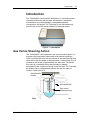
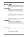
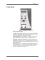
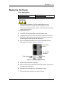
TurboVap 96 Concentration Workstation User’s Manual Copyright 2010, Biotage AB. All rights reserved. P/N 128097 Rev. 00 Preface 2 Preface Copyright This manual is published by Biotage AB,10430 Harris Oaks Blvd. Suite C, Charlotte, NC 28269 U.S.A. Copyright 2010, Biotage AB. All rights reserved. Reproduction by any means or in any form of this manual or the products it describes is prohibited. Trademarks Biotage and TurboVap are trademarks of Biotage. Microsoft and Windows are either registered trademarks or trademarks of Microsoft Corporation in the United States and/or other countries. All other trademarks and registered trademarks are the property of their respective holders. Content The information in this manual may contain typographical errors or technical inaccuracies and is subject to change without notice. Modifications may also be made to the product described in this manual at any time. Proper Equipment Operation The TurboVap 96 Concentration Workstation is a microprocessor-controlled instrument that provides simultaneous, automated concentration of multiple samples, unattended operation, convenience, and speed. The TurboVap 96 can simultaneously process one or two 96-well microplates or deepwell plates. It is the customer's responsibility to determine suitable methods for evaporation of their samples. WARNINGS • • • The TurboVap 96 is NOT designed for in vitro testing or for use with highly corrosive acids. To reduce the risk of electric shock, do not remove the cover. No user serviceable parts are inside. Refer to qualified service personnel if help is required. Use this product only in the manner described in this manual. If the equipment is used in a manner not specified by the manufacturer, the protection provided by the equipment may be impaired. AVERTISSEMENTS • • P/N 128097 Rev. 00 Pour réduire le risque de choc électrique, ne pas retirer le couvercle. Ce produit ne contient aucune pièce pouvant être réparée par l’utilisateur. Au besoin, confier l’appareil à un réparateur qualifié. Ce produit ne doit être utilisé que comme décrit dans ce manuel. Si cet appareil est utilisé d’une manière autre que celle spécifiée par le fabricant, la protection fournie par l’appareil peut être entravée. TurboVap 96 User’s Manual Biotage AB Preface 3 Product Safety Warning The TurboVap 96 power switch is the same type of power switch used on most laboratory equipment such as gas chromatographs, spectrophotometers, liquid chromatographs, and computers. The TurboVap products are safely used in the laboratory when “Good Laboratory Practices” are followed as with any other lab equipment. All fans are brushless motor fans and will not ignite vapors. The TurboVap is not classified as “Explosion Proof” and its use is at the discretion and risk of the operator or laboratory supervisor/manager. Your TurboVap product has been designed with safety as a foremost consideration. These products are equipped with a non-arcing fan, solid state electronics, and provisions for vapor collection. Do not change the configuration of the TurboVap 96 ventilation system. Please consult with Biotage if you have any questions or concerns regarding this subject. WARNING TurboVap products are NOT classified as “Explosion Proof.” The power switch is an arcing source and could ignite explosive vapors if present. Contact Biotage 1-Point Support Biotage 1-Point Support provides expert services including telephone troubleshooting of products, repair instructions, service dispatching and replacement part information. Before you call: Check the online Help and the manual for a probable cause and solution to your question. Have the following information available for the customer support representative: • Workstation serial number(s) • If applicable, the error displayed on the LCD display To reach the Biotage 1-Point Support: US: 1-800-446-4752 or [email protected] Europe and Rest of the World: +46 18 56 57 11 or [email protected] Japan: +81 422 28 1233 or [email protected] Biotage Product Repair Depot The Biotage Product Repair Depot offers product repair services, upgrades, refurbishment and installation at reasonable costs and with quick turnaround for all customer-owned equipment and accessories. For further information or to obtain a quotation for services, contact the Depot: US: 1-800-446-4752 or [email protected] Europe and Rest of the World: +46 18 56 57 11 or [email protected] Japan: +81 422 28 1233 or [email protected] Features of the Biotage Product Repair Depot: • Factory-trained repair technicians • Two week turnaround from receipt at Biotage P/N 128097 Rev. 00 TurboVap 96 User’s Manual Biotage AB Preface 4 Shipping: Customers are responsible for shipments both to and from Biotage, specifying the carrier and choice of service. Return Policy: To ensure a safe environment for all our technicians, it is mandatory for each returned product to include our chemical questionnaire stating contact chemicals, chemicals used during application and cleaning steps taken prior to shipment. Processing: Once the product is returned, it is evaluated for necessary repairs. The customer is contacted with an estimate and may choose to go ahead with the repair or decline service. If service is denied, a minimum evaluation charge may apply. Upon completion of the repair, a purchase order or appropriate means of payment is required before return shipment. Service and Customer Support Plans Biotage offers a full range of services to ensure your success. From our original factory warranty through a comprehensive line of customer support plans, Biotage AB offers you Field Service Engineers and In-house Specialists who are dedicated to supporting your hardware, software and application development needs. US: 1-800-446-4752 or [email protected] Europe and Rest of the World: +46 18 56 57 11 or [email protected] Japan: +81 422 28 1233 or [email protected] Our programs can include such useful services as: • preventative maintenance • diagnostic servicing performed on-site by Biotage AB field service engineers • extended use of the Biotage AB Customer and Technical Support Center • automated, remote troubleshooting • software updates • after-hour, weekend and holiday support • repair depot servicing • parts, labor and travel expense coverage • other customized services upon request FCC This device complies with part 15 of the FCC (United States Federal Communications Commission) Rules. Operation is subject to the following two conditions: • This device may not cause harmful interference, and • This device must accept any interference received, including interference that may cause undesired operation. P/N 128097 Rev. 00 TurboVap 96 User’s Manual Biotage AB Preface 5 CE This device complies with all CE rules and requirements. NOTE Changes or modifications to this equipment not expressly approved by the party responsible for compliance could void the user’s authority to operate the equipment. REMARQUE Tout changement ou modification apporté à cet instrument non expressément approuvé par l’entité responsable de la conformité peut annuler l’autorisation d’opérer l’appareil accordée à l’utilisateur. Table of Symbols Table 1 contains symbols that identify particularly important information and alert you to the presence of hazards. These symbols may appear in this manual and/or on the product it describes. Table 1. Important Symbols Symbol Symbole Description Description DANGER: An imminently hazardous situation, which, if not avoided, will result in death or serious injury. DANGER : Situation présentant un danger imminent qui, s’il n’est pas éliminé, peut entraîner des blessures graves, voire la mort. WARNING: Caution, risk of danger. Refer to the User’s documentation. AVERTISSEMENT : Attention, danger potentiel. Se reporter à la documentation de l’utilisateur. NOTE: A cautionary statement; an operating tip or maintenance suggestion; may result in instrument damage if not followed. REMARQUE : Énoncé indiquant une précaution à prendre, un conseil de fonctionnement ou une suggestion d’entretien; son non-respect peut provoquer des dommages à l’instrument. Hazardous voltage; risk of shock injury. Tension dangereuse; risque de blessure par électrocution. Crush hazard. Risk of body parts, hair, jewelry, or clothing getting caught in a moving part. Danger d’écrasement. Faire attention que les parties corporelles, les cheveux, les bijoux ou les vêtements ne soient pas pris dans une pièce mobile. P/N 128097 Rev. 00 TurboVap 96 User’s Manual Biotage AB Preface 6 Table 1. Important Symbols (Continued) Symbol Symbole Description Description Risk of puncture injury. Risque de blessure par piqûre. Risk of eye injury; wear safety glasses. Risque de lésion oculaire; porter des lunettes de sécurité. Risk of exposure to biohazards. Risque d’exposition à biohazards. Risk of fire. Risque d’incendie. Risk of poison. Risque d’empoisonnement. Risk of explosion. Risque d’explosion. Hazardous fumes. Émanations dangereuses. Hot surface; risk of burns. Surface chaude; risque de brûlures. Protective ground symbol. Symbole de terre de protection. Ground symbol. Symbole de terre. Fuse. Fusible. Alternating current. Courant alternatif. On (supply). Marche (alimentation). Off (supply). Arrêt (alimentation). CE compliance mark. Marque de conformité CE. Signifies that the unit has passed safety tests for grounding, power line transience, and current leakage. Signifie que l’appareil a réussi les tests de sécurité pour la mise à la terre, le courant transitoire de ligne d’alimentation et la perte de courant. P/N 128097 Rev. 00 TurboVap 96 User’s Manual Biotage AB Preface 7 Table 1. Important Symbols (Continued) Symbol Symbole Description Description Input. Entrée. Output. Sortie. Equipment labels are color coded: Les étiquettes de l’appareil sont codées couleur: P/N 128097 Rev. 00 Yellow Red Blue Green Jaune Rouge Bleu Vert Caution, risk of danger Stop Mandatory action Safe condition or information Attention, danger potentiel Arrêter Intervention obligatoire Condition sûre ou informations de sécurité TurboVap 96 User’s Manual Biotage AB Table of Contents 8 Table of Contents Preface .................................................................................................................... 2 Introduction .......................................................................................................... 10 Gas Vortex Shearing Action .............................................................................. 10 Microplate Heating ........................................................................................... 11 Vapor Removal ................................................................................................. 11 Automated Evaporation ..................................................................................... 11 Adjustable ......................................................................................................... 11 Convenience ..................................................................................................... 11 Mild Conditions ................................................................................................. 11 Instant On Heat ................................................................................................. 11 Cover Sensor .................................................................................................... 11 Requires No Exhaust Hood ............................................................................... 12 Multiple Sample Processing .............................................................................. 12 Microplates and Deepwell Plates ....................................................................... 12 Hardware ............................................................................................................... 13 TurboVap 96 - Front .......................................................................................... 13 TurboVap 96 - Cover Open ............................................................................... 14 TurboVap 96 - Rear........................................................................................... 15 TurboVap 96 - Left Side .................................................................................... 16 Microplate Adapter ............................................................................................ 16 Front Panel ....................................................................................................... 17 Installation ............................................................................................................ 19 Unpacking the TurboVap 96 .............................................................................. 19 Parts Supplied................................................................................................... 19 Items Required But Not Included ....................................................................... 19 Site Preparation ................................................................................................ 20 Installing the TurboVap 96................................................................................. 22 Connect the Gas Supply .............................................................................. 22 Install the Venting Hose ............................................................................... 23 Connect the Power Cord.............................................................................. 24 Turn On the Power ...................................................................................... 24 Power-Up Diagnostics ................................................................................. 24 Determining Optimal Concentration Conditions ................................................. 25 Considerations when Selecting Plate Temperature .......................................... 25 Considerations When Setting the Gas Flow Rate ............................................. 26 Operation .............................................................................................................. 27 Preparing the Unit ............................................................................................. 27 Setting the Gas Time (Evaporation Time) for Position 1 .................................... 27 Setting the Plate Temperature for Position 1 ..................................................... 28 Setting the Flow Rate for Position 1 .................................................................. 28 Setting the Gas Time (Evaporation Time) for Position 2 .................................... 29 Setting the Plate Temperature for Position 2 ..................................................... 29 P/N 128097 Rev. 00 TurboVap 96 User’s Manual Biotage AB Table of Contents 9 Setting the Flow Rate for Position 2 .................................................................. 30 Starting the Concentration ................................................................................. 31 Elapsed Time Display .................................................................................. 32 Cycle Readout ............................................................................................. 32 Pausing the Concentration ................................................................................ 33 Restarting the Concentration ............................................................................. 33 Completing the Concentration ........................................................................... 33 Maintenance .......................................................................................................... 34 Daily Maintenance............................................................................................. 34 Routine Maintenance ....................................................................................... 34 Replacing the Fuses.......................................................................................... 35 Long Term Storage ........................................................................................... 36 Troubleshooting .................................................................................................. 37 Troubleshooting the Concentration .................................................................... 37 Troubleshooting the Front Panel Display ........................................................... 38 Workstation Not Operational ............................................................................. 39 Specifications ....................................................................................................... 40 Index ...................................................................................................................... 43 P/N 128097 Rev. 00 TurboVap 96 User’s Manual Biotage AB Introduction 10 Introduction The TurboVap 96 Concentration Workstation is a microprocessorcontrolled instrument that provides simultaneous, automated concentration of multiple samples, unattended operation, convenience, and speed. The TurboVap 96 can simultaneously process one or two 96-well microplates or deepwell plates. Figure 1. TurboVap 96 Gas Vortex Shearing Action The TurboVap 96 uses a patented “gas vortex shearing action” to maintain high evaporation rates under mild thermal conditions. When you close the cover, 96 gas nozzles in the manifold align with each well of the microplate or deepwell plate. A helical flow of air is created by the stream of gas directed into each well. The helical flow sets up a vortexing action that provides for sample homogeneity and continuous rinsing of the well wall. The TurboVap 96 enables you to independently control the gas flow rate for Position 1 and Position 2. Gas Manifold Nozzle Microplate Well Gas Vortex Shearing Action Figure 2. Gas Manifold Nozzle in Microplate Well P/N 128097 Rev. 00 TurboVap 96 User’s Manual Biotage AB Introduction 11 Microplate Heating Heaters below the microplate locating plates direct hot air through holes in the microplate locators, toward each well in the microplate. The forced hot air and the circulating gas quickly evaporates the solvent in each well. Vapor Removal The solvent vapors are removed by a blower at the front of the TurboVap 96 that blows air across the top of the microplates and through the exhaust port at the back of the workstation. From the exhaust port, the venting hose must be routed to a suitable outside ventilation system. Automated Evaporation The TurboVap 96 uses an integrated microprocessor to automatically time the evaporation, control the temperature, monitor gas flow rates, automatically turn off the gas and heaters, and perform operational diagnostics Adjustable The TurboVap 96 enables you to concentrate for a set time, concentrate until stopped manually, and optimize the concentration rate by adjusting the gas pressure and temperature. Convenience You can start a run of samples and leave the instrument unattended. When the concentration has finished, the gas flow turns off automatically, the temperature drops to 37° C, and the workstation sounds an alarm every 30 seconds until you remove the samples or press the Start • Stop button. Mild Conditions The heaters provide sufficient warming without harming the sample. Instant On Heat When you turn the workstation on, the heaters heat up to the set Plate Temperature or to 37C if the temperature is set above 37C. Cover Sensor A sensor in the cover turns off the gas to protect from gas vapors if the cover is opened during concentration. P/N 128097 Rev. 00 TurboVap 96 User’s Manual Biotage AB Introduction 12 Requires No Exhaust Hood The cover and exhaust system permit the unit to be placed on a bench rather than taking up valuable hood space. Multiple Sample Processing Each sample position provides 96 gas manifold nozzles that extend into the wells of the microplates or deepwell plates to supply gas for concentration. Using both position 1 and 2 allows up to 192 samples to be processed simultaneously. Microplates and Deepwell Plates Either one or two 96-well microplates or deepwell plates can be used. Deepwell plates are placed directly on the surface of the locator plate. Microplates use the supplied adapter to position the top of the microplate at the same level as the top of a deepwell plate. P/N 128097 Rev. 00 TurboVap 96 User’s Manual Biotage AB Hardware 13 Hardware TurboVap 96 - Front Cover Front Panel Position 1 Gas Regulator Position 2 Gas Regulator Figure 3. TurboVap 96 Hardware, Front View Front Panel Controls the setup and operation of the Concentration Workstation. See “Front Panel” on page 17 for details. Cover Holds the gas manifold that directs the gas into the wells of each plate to create the gas vortex shearing action. Gas Regulator Knobs Set the flow rate for all 96 gas manifold nozzles. The left gas regulator knob controls the flow rate to Position 1; the right knob, to Position 2. Pull out knob, turn, then push knob in to make adjustments. P/N 128097 Rev. 00 TurboVap 96 User’s Manual Biotage AB Hardware 14 TurboVap 96 - Cover Open Gas Manifolds Plate Locations Microplate Adapter Heater Figure 4. TurboVap 96 with Cover Open Gas Manifolds Each manifold consists of 96 individual gas nozzles, which fit inside each microplate well. Each nozzle supplies gas to concentrate the sample in one microplate well. Microplates and deepwell plates Hold the samples for concentration. Microplate Adapter Used with microplates so that when the cover is closed, the manifold nozzles fit inside each microplate well. Not used with deepwell plates. Heater assembly Warms the samples during concentration to aid in evaporation. P/N 128097 Rev. 00 TurboVap 96 User’s Manual Biotage AB Hardware 15 TurboVap 96 - Rear Alarm Volume Control Service Panel Exhaust Port Quick-disconnect Gas Inlet Power Entry Port Figure 5. TurboVap 96 Hardware, Rear View Alarm Volume Control Adjusts the loudness of the beeper. Service Panel Used by service personnel to access the exhaust blower and the sensor/interconnect module. Quick-disconnect Gas Inlet Connects the gas supply to the workstation. The fitting has an internal shutoff that allows you to disconnect the workstation from the gas supply without shutting off the gas supply itself. Exhaust port Allows you to connect a hose to channel the solvent vapors to a suitable outside vent location. Power entry port Connects the power cord and houses the fuse(s). P/N 128097 Rev. 00 TurboVap 96 User’s Manual Biotage AB Hardware 16 TurboVap 96 - Left Side Position 1 Gas Regulator Power Switch Figure 6. TurboVap 96 Hardware, Left Side View Power Switch Turns the power on and off. Microplate Adapter Figure 7. Microplate Adapter Microplate Adapter Used to raise microplates up to the proper height. Not used with deepwell plates. P/N 128097 Rev. 00 TurboVap 96 User’s Manual Biotage AB Hardware 17 Front Panel Figure 8. TurboVap 96 Front Panel Display Indicator Lights Indicate which setting is displayed in the Value and Units displays. Gas Time - displays the length of time to evaporate, from 1 to 99 minutes. 00 evaporates until manually stopped. Plate Temperature - the temperature, in degrees Celsius, of the airflow under the plate. Range is from 20 (ambient) to 80C. Flow Rate - displays the total gas flow for all 96 nozzles in each plate position. Range is from 5 to 99 standard cubic feet per hour (SCFH). Adjust the flow rate using the gas regulators on each side of the TurboVap 96. Elapsed Time - the time, in minutes, that has elapsed since the start of evaporation; “--” means not started. Range is from 0 to 99 minutes. If the Gas Time is set to manual mode (00), after 99 minutes the elapsed time displays “”. P/N 128097 Rev. 00 TurboVap 96 User’s Manual Biotage AB Hardware 18 Cycle Readout - when lit, all of the parameters, one at a time, for any position that is running are displayed. If neither position is running, the display shows the set values for both positions. The plate temperature display shows the present temperature when evaporation is in process for that position; otherwise, it shows the set value. Select Button Advances the display indicator to the next option. If you press the Select button after turning on the workstation, the TurboVap enters diagnostics mode, displaying the current firmware revision. Set Button This button sets currently selected setting (Gas Time or Plate Temperature) to the displayed value. The Set button only sets the Gas Time and Plate Temperature. The Set button has no effect on the other settings. Up and Down Arrow Buttons Increase or decrease the value in the display. Used to set the values for Gas Time and Plate Temperature. Start Stop Buttons Start or stop evaporation. During evaporation, the Position light is green. Over Temp Light Turns on (red) when the present temperature of one of the position is 10C greater than the set plate temperature. When the temperature drops below this value, the light turns off. The light may indicate a heater runaway caused by a defective relay or temperature sensor. Low Flow Light Indicates a low gas flow rate, possibly because the gas is running out, or the flow regulator was not adjusted before starting the evaporation. If the flow rate drops below 5 SCFH when the evaporation is in process, the Low Flow LED lights and the alarm beeps continuously. P/N 128097 Rev. 00 TurboVap 96 User’s Manual Biotage AB Installation 19 Installation This section describes how to unpack the TurboVap 96, how to prepare the site, and how to install the TurboVap 96. Unpacking the TurboVap 96 Unpack the shipping container and verify that all parts listed below are included. If any part is damaged or missing, contact Biotage (see “Contact Biotage 1-Point Support” on page 3). Parts Supplied The TurboVap 96 includes the following parts: • Concentration Workstation • Power Cord(s) - 220V models include two power cords, one for EU and one for UK • Venting Hose 12.5 ft (3.8 m) • 3/8 in. (9.5 mm) ID Gas tubing • Bag of two 3/8 in. (9.5 mm) Barb Fittings (1/8 in. NPT and 1/4 in. NPT) • Coupling Insert • Two hose clamps • User’s Manual CD • Microplate Adapters (2) Items Required But Not Included • P/N 128097 Rev. 00 Inert gas supply (nitrogen) with two-stage regulator TurboVap 96 User’s Manual Biotage AB Installation 20 Site Preparation Before installing the TurboVap 96 Concentration Workstation, you must have an appropriate location with available gas and electrical sources and adequate ventilation as specified by these site preparation requirements. Space Minimum bench space needed for the Concentration workstation and any accessories: • Height: 12 inches (30.5 cm) • Width: 23.5 inches (59.7 cm) • Depth: 12.5 inches (31.8 cm) • Open Cover: 21 inches (53.3 cm) Work Area Flat, level, stable surface Indoor use only within 12.5 ft (3.8 m) of proper ventilation Gas Supply You must use clean, dry, regulated nitrogen or other suitable gas. Use the supplied 3/8 in. (9.5 mm) ID gas tubing for connection of the gas supply. A carbon trap is also recommended. Use of compressed air could contribute to the oxidation of some phenolic compounds and reduce sample recoveries. WARNING Never use hydrogen or other flammable gases. The wrong gas may explode or catch on fire. Compressed Gas Supply Inlet Pressure Minimum Recommended Maximum 30 psi (2.1 bars) 60-70 psi (4.1 - 4.8 bars) 80 psi (5.52 bars) 1 bar = 100 kilopascals. Devices added to the inlet supply line, such as moisture traps or filters, must not drop the pressure under 30 psi (2.1 bars) measured at the TurboVap 96 inlet fitting. P/N 128097 Rev. 00 TurboVap 96 User’s Manual Biotage AB Installation 21 WARNING To avoid injury to yourself or damage to the instrument, DO NOT exceed 80 psi (5.52 bars) maximum supply pressure. Exhaust Duct The exhaust duct requires a 2-inch (5.1-cm) diameter venting hose (supplied). The exhaust duct MUST be routed to a suitable ventilation system vented outside the laboratory. WARNING Exhaust gases may be hazardous. Consult the Material Safety Data Sheets (MSDS) for all of the solvents used. Power P/N 128097 Rev. 00 100/120 VAC Model 220/240 VAC Model Input Voltage 100/120 VAC +/- 10% 220/240 VAC +/- 10% Line Frequency 50 - 60 Hz 50 - 60 Hz Fuse (1) 6A, F250V (P/N 38904) (2) 3.15A, F250V (P/N 38902) Ground The 3-prong power cord plug supplies the ground. TurboVap 96 User’s Manual Biotage AB Installation 22 Installing the TurboVap 96 Connect the Gas Supply WARNING Never use hydrogen or other flammable gases. The wrong gas may explode or catch on fire. To connect the gas supply: 1 Turn off the gas supply. 2 Determine if an in-line carbon trap is necessary. 3 Place one of the supplied clamps over each end of the 3/8-in. (9.5 mm) tubing supplied. 4 Connect one end of the tubing to the gas supply and tighten the clamp to secure the tubing onto the barbed fittings. 5 Connect the other end to the barbed fitting on the Coupling Insert and tighten the clamp. 6 Snap the Coupling Insert (O-ring end) into the Quick-disconnect Gas Inlet on the back of the TurboVap 96. 7 Turn on the gas supply. 3/8” ID Gas Tubing O-Ring Release Button Barbed End Clamp Quick-disconnect Coupling Insert (with internal shutoff) Gas Inlet Side view of back of Concentrator Figure 9. Connecting the Gas Supply P/N 128097 Rev. 00 TurboVap 96 User’s Manual Biotage AB Installation 23 WARNING To avoid injury to yourself or damage to the instrument, DO NOT exceed 80 psi (5.52 bars) maximum supply pressure. Install the Venting Hose If the TurboVap 96 is not placed under a hood, install the venting hose using the following procedure. 1 Slide one end of the venting hose over the exhaust port. Exhaust port Figure 10. Installing the Venting Hose 2 Route the hose to a suitable outside-vented location or hood. Ensure that the ventilation system is operating whenever the TurboVap 96 is in use. WARNING • • Gas fumes exiting this instrument can contaminate the air. Maintain proper ventilation. Use only a venting hose with appropriate length and internal diameter to avoid excessive pressure drop. The following hoses can be used to vent the TurboVap 96: P/N 128097 Rev. 00 Maximum Hose Length Internal Diameter 12.5 ft (3.8m) 2 inch (5cm) I.D. 30 ft (9.1m) 2.5 inch (6.4cm) I.D. 60 ft (18.2m) 3 inch (7.6cm) I.D. TurboVap 96 User’s Manual Biotage AB Installation 24 Connect the Power Cord 1 Plug the power cord securely into the receptacle on the back of the unit. Make sure that the plug is fully inserted. 2 Connect the 3-pronged end to an appropriate power source. WARNING To avoid the risk of fire or electrical shock, plug the power cord into a properly grounded outlet. Turn On the Power To turn on the TurboVap 96, turn ON the power switch located on the lower left side of the unit. When the power is turned on, the internal air temperature will heat up to the previously set plate temperature if it was set to below 37°C; or it will heat up to 37°C if it is set above this value. Power-Up Diagnostics When the power is turned on, both the Value and Units displays show 88, and all LEDs are lit for 1.5 seconds. Confirm that all lights are working properly. (If you press the Select button while in this state, the workstation enters diagnostics mode, displaying the current firmware revision.) After 1.5 seconds, initialization continues. Also during this time, raising and lowering the cover sounds the beeper to confirm the cover switch is functioning. After initialization, the workstation lights the Position 1 – Gas Time light and displays the Gas Time previously set for Position 1. P/N 128097 Rev. 00 TurboVap 96 User’s Manual Biotage AB Determining Optimal Concentration Conditions 25 Determining Optimal Concentration Conditions You should determine the settings that will best concentrate your samples before operation. You should determine the desired: • Gas time (evaporation time) • Plate temperature • Flow rate Considerations when Selecting Plate Temperature The two heaters operate over a temperature range of 20C (ambient) to 80C ±5C. The mild temperature range eliminates “hot” spots and improves sample recovery for more volatile compounds. When selecting the Plate Temperature, consider the following: • Faster evaporation occurs as the plate temperature is increased; however, highly volatile analytes can be lost if allowed to sit for extended periods of time in a hot environment. • You can use a Plate Temperature above the boiling point of your solvent if the gas flow rate is high enough to create a cooling effect over the solvent. • The cooling effect of both the gas flow and the resulting evaporation of a solvent will keep the internal temperature below that of the set plate temperature. • The temperature of each well during the evaporation process will be below the set plate temperature. Once the liquid in the well evaporates and the gas flow stops, the well temperature will rise. When the workstation is turned on, the plate temperature warms up to wait for the next evaporation process. If the cover is opened after the evaporation process begins, the following chart shows how the temperature changes. Plate Temp Plate Temp setting is < 37C, setting is > 37C, system runs at … system runs at … State of workstation Cover Turned on and initialized. Either open or closed Set temperature 37C Evaporation has started Closed Set temperature Set temperature P/N 128097 Rev. 00 TurboVap 96 User’s Manual Biotage AB Determining Optimal Concentration Conditions 26 Cover Plate Temp Plate Temp setting is < 37C, setting is > 37C, system runs at … system runs at … Evaporation has started Open Set temperature 37C Gas flow time is complete Either open or closed Set temperature 37C State of workstation Considerations When Setting the Gas Flow Rate When selecting the gas Flow Rate, consider that: • A higher flow rate can cause a faster evaporation rate. • An excessively high flow rate can cause the loss of analyte due to splashing. • For the best results, use the highest gas pressure possible without causing splashing. • As the sample volume decreases during concentration, increasing the flow rate will reduce the overall concentration time. • For proper operation, the pressure to the workstation should be at least 30 psi (2.07 bars). To avoid damage, the supply inlet pressure must not exceed 80 psi (5.52 bars); 60 – 70 psi (4.1 – 4.8 bars) is recommended. WARNING • P/N 128097 Rev. 00 To avoid injury to yourself or damage to the instrument, DO NOT exceed 80 psi (5.52 bars) maximum supply pressure. TurboVap 96 User’s Manual Biotage AB Operation 27 Operation This section describes how to operate the TurboVap 96. For each of the two positions, you can choose: • Evaporation time from 1 to 99 minutes, or until stopped manually. • Plate temperature from 20 (ambient) to 80C. • Gas flow rate from 5 to 99 standard cubic feet/hour (SCFH). You can start or stop each position at any time independent of the other position. Preparing the Unit To prepare to start a concentration: 1 Check that the incoming gas supply is turned on and has sufficient reserve for the sample run. 2 With the cover closed, turn on the power. The Value and Units displays show 88, and all LEDs turn on for 1.5 seconds. After initialization, the Position 1 – Gas Time LED turns on and the Gas Time set for Position 1 displays. 3 Set the desired Gas Time, Plate Temperature, and Flow Rate for Position 1 and/or Position 2 as described below. Setting the Gas Time (Evaporation Time) for Position 1 After initialization is complete, the Gas Time light for position 1 is lit and the Value display blinks and shows the number of minutes the evaporation will run. To set the Gas Time: 1 Press the up ( ) or down ( ) arrow buttons to increase or decrease the time. The Gas Time can be set from 1 to 99 minutes and has a one-second resolution. Setting the Gas Time to 00 indicates manual operation. If you set the Gas Time to 00, you must manually stop the gas flow using the Start Stop button. 2 When the desired Gas Time is displayed, press the Set button. The selected Gas Time is saved and the Plate Temperature for position 1 displays. If you press the Select button before pressing the Set button, the time is reset to the original value and the Plate Temperature for position 1 displays. P/N 128097 Rev. 00 TurboVap 96 User’s Manual Biotage AB Operation 28 Setting the Plate Temperature for Position 1 To set the Plate Temperature for position 1: 1 Press the Select button until the Plate Temp light for Position 1 is lit. The display blinks and shows the previous temperature set for position 1. 2 Press the up ( ) or down ( ) arrow buttons to increase or decrease the temperature. The Plate Temperature can be set from 20ºC (ambient) to 80C. (The Units display shows C.) The plate temperature is maintained within this setting 5C. 3 Press the Set button to save the new temperature and display the flow rate for position 1. If you press the Select button before pressing the Set button, the plate temperature is reset to the original value and the Flow Rate for position 1 displays. During evaporation, the display shows the actual temperature of the position, not the set temperature. NOTES • • The cooling effect of both the gas flow and the evaporation of the solvent will keep the internal temperature below the set plate temperature. The temperature of each well during the evaporation process will be below that of the plate temperature. Once the liquid in the well evaporates and the gas flow stops, the well temperature will rise. Setting the Flow Rate for Position 1 The flow rate is the total flow for the 96 nozzles in Position 1; it is not a per-nozzle flow rate. Change the flow rate by adjusting the gas regulator knobs on the sides of the TurboVap 96. To set the Flow Rate for position 1: 1 Press the Select button until the Flow Rate light for Position 1 is lit. The display blinks and shows “--” if the gas is off, the cover is open, or the left gas regulator knob is closed. The Units display shows Fh for Standard Cubic Feet per Hour (SCFH). 2 Make sure the source input gas is on. 3 Close the cover and press the Position 1 Start • Stop button to turn on the gas to position 1. 4 Pull the left Gas Regulator Knob out. P/N 128097 Rev. 00 TurboVap 96 User’s Manual Biotage AB Operation 29 Setting the Flow Rate for Position 1 (Continued) 5 Turn the gas regulator knob to adjust the flow rate as desired. The flow rate can be set from 5 to 99 SCFH. (The Set button and the up and down buttons have no effect on this setting.) NOTE Turn the gas regulator knob slowly. The flow sensors are very sensitive and may have some delay before equalizing. 6 Once adjustments are made, push the Gas Regulator Knob back in. 7 Press the Position 1 Start • Stop button to turn off the gas. 8 Press the Set button. If you press the Select button, the Elapsed Time light for position 1 lights and Position 1 elapsed time is displayed. Setting the Gas Time (Evaporation Time) for Position 2 Setting the Gas Time for position 2 is similar to setting the gas time for position 1: 1 Press the Select button until the Gas Time LED light for position 2 is lit. 2 Press the up ( ) or down ( ) arrow buttons to display the desired time. 3 Press the Set button to save the selected time or press the Select button to reset the time to the original value. The Plate Temperature for position 2 is selected. Setting the Plate Temperature for Position 2 Setting the Plate Temperature for position 2 is similar to setting the Plate Temperature for position 1: 1 Press the Select button until the Plate Temp light for position 2 is lit. The display shows the previous set temperature for position 2. 2 Press the up ( ) or down ( ) arrow buttons to display the desired plate temperature. P/N 128097 Rev. 00 TurboVap 96 User’s Manual Biotage AB Operation 3 30 Press the Set button to save the selected temperature or press the Select button to reset the temperature to the original value. The Flow Rate for position 1 displays. Setting the Flow Rate for Position 2 The flow rate is the total flow for the 96 nozzles in Position 2; it is not a per-nozzle flow rate. You change the flow rate by adjusting the gas regulator knobs on the sides of the TurboVap 96, not by changing the setting on the display. 1 Press the Select button until the Flow Rate light for Position 2 is lit. 2 Make sure the source input gas is on. 3 With the cover closed, press the Position 2 Start • Stop button to turn on the gas to position 2. 4 Pull the right Gas Regulator Knob out. 5 Turn the gas regulator knob to adjust the flow rate as desired. The flow rate can be set from 5 to 99 SCFH. (The Set button and the up and down buttons have no effect on this setting.) NOTE Turn the gas regulator knob slowly. The flow sensors are very sensitive and may have some delay before equalizing. 6 Once adjustments are made, push the Gas Regulator Knob back in. 7 Press the Position 2 Start • Stop button to turn off the gas. 8 Press the Set button. If you press the Select button, the Elapsed Time light for position 2 lights and Position 2 elapsed time is displayed. P/N 128097 Rev. 00 TurboVap 96 User’s Manual Biotage AB Operation 31 Starting the Concentration After setting the desired Gas Time, Plate Temperature, and Flow Rate for Position 1 and/or Position 2, you are ready to start the concentration. 1 Place the microplate adapter into any position where you will be using a microplate. 2 Place the deepwell plates or microplates in the desired positions. Gas Manifolds Position 1 Position 2 with microplate adapter Figure 11. Inserting Microplates into the Workstation 3 Close the cover. 4 To start the concentration in position 1, press the Position 1 Start • Stop button. To start the concentration in position 2, press the Position 2 Start • Stop button. 5 If desired, you can adjust either Gas Regulator Knob during the concentration process. Be sure to pull the knob out before making any adjustments to the setting. NOTE The Gas Time and Plate Temperature cannot be changed once the concentration has started. P/N 128097 Rev. 00 TurboVap 96 User’s Manual Biotage AB Operation 32 Elapsed Time Display The Value display blinks “- -” when the position has been stopped or has not been started. If evaporation has started, the Value display shows the number of minutes since the start of the evaporation. The maximum elapsed time is determined by the Gas Time setting, which can range from 1 to 99 minutes. If the Gas Time is set to 00, the elapsed time displays “” after 99 minutes. The Set button and the up and down buttons have no effect on the elapsed time display. If you press the Select button, the Cycle Readout light is lit and the display rotates as described below. Cycle Readout When Cycle Readout is selected, the Value and Units displays show the current conditions for each parameter in the following sequence: • Position 1 - Gas Time, • Position 1 - Plate Temp • Position 1 - Flow Rate • Position 1 - Elapsed Time • Position 2 - Gas Time • Position 2 - Plate Temp • Position 2 - Flow Rate • Position 2 - Elapsed Time After displaying the Position 2 – Elapsed Time, the display cycles back to Position 1 - Gas Time. If evaporation is in process, the current plate temperature is displayed, not the set Plate Temperature. If the current temperature is +/- 10C from the set Plate Temperature, the displayed temperature blinks. If only one position is running, the display only shows the settings for that position. If both positions are running or stopped, the settings for both positions are displayed. If you press the Select button when Cycle Readout is selected, the display shows the previously set Gas Time for Position 2, and the Position 2 – Gas Time LED will light. (The up, down, and Set buttons have no effect when Cycle Readout is selected.) P/N 128097 Rev. 00 TurboVap 96 User’s Manual Biotage AB Operation 33 Pausing the Concentration The gas flow and the evaporation time continue as long as the cover is closed. When the cover is opened, an alarm beeps for 1 second. The evaporation timer and the gas flow pause and will not turn on while the cover is in the open position. When the cover is closed, the evaporation continues. Restarting the Concentration If the evaporation has started, pressing the Start • Stop button stops the evaporation and the alarm beeps for 1 second. Pressing the Start • Stop button again resets the elapsed time to zero and restarts the evaporation process. Completing the Concentration When the evaporation is complete, the Position light blinks and the alarm beeps every 30 seconds until you press the Position Start • Stop button or open the cover. If you close the cover, the position is turned off. NOTES • • P/N 128097 Rev. 00 The heaters will maintain the set Plate Temperature if it was set to below 37°C; or it will go to 37°C if it is set above this value. If you set the gas time to 00, you must manually stop the concentration using the Start Stop button. TurboVap 96 User’s Manual Biotage AB Maintenance 34 Maintenance This section of the manual includes: • “Daily Maintenance” on page 34 • “Routine Maintenance ” on page 34 • “Replacing the Fuses” on page 35 • “Long Term Storage” on page 36 Daily Maintenance • During Power-Up diagnostics, confirm that all displays are accurate. • Check that the tank has enough nitrogen for daily operation. WARNING Never use hydrogen or other flammable gases. The wrong gas may explode or catch on fire. • Avoid spilling any solvents on the control panel. • Avoid spilling any solvents on the heaters. Routine Maintenance Panel Avoid contact with solvents and remove dirt buildup on the control panel. To clean, use a mild cleaning solution on a damp cloth. Do not spray cleaner directly onto the control panel. Exterior Clean exterior surfaces with a damp cloth and mild cleaning solution when necessary. Cover Keep cover clean and do not use the cover as a shelf. Gas Supply Periodically check gas hose and fittings for leaks. Exhaust Port Periodically check for leaks in hose. Replace if necessary. P/N 128097 Rev. 00 TurboVap 96 User’s Manual Biotage AB Maintenance 35 Replacing the Fuses Fuse Requirements: 100/120 VAC Model 220/240 VAC Model (1) 6A, F250V (P/N 38904) (2) 3.15A, F250V (P/N 38902) WARNING • • Electrical shock hazard. Turn the power switch off and disconnect the power supply before changing the fuses. For continued fire protection, replace fuses only with ones of the same type and rating. To replace the fuses: 1 Turn OFF the AC power and unplug the power cord. 2 Locate the Power Entry Port fuse holder on the side of the unit. 220/240V units have two fuse holders in the power entry port. Always replace both fuses at the same time. 3 Use a flat-blade screwdriver to turn the fuse holder(s) from horizontal to vertical as shown in Figure 12. Fuse Holder locked Fuse Holder unlocked Fuse Holder Fuse Figure 12. Replacing the Fuses 4 Remove the fuse holder and fuse. 5 Remove the fuse from the fuse holder and replace it with one of the same type and rating. 6 Replace the fuse holder(s) in the power entry port. 7 Plug in the power cord and turn on the power. P/N 128097 Rev. 00 TurboVap 96 User’s Manual Biotage AB Maintenance 36 Long Term Storage If the TurboVap will be stored for an extended period of time: 1 Turn the unit off and unplug the power cord. 2 Remove plates. 3 Turn off and disconnect the air/gas supply. 4 Close the cover. 5 Cover the unit to prevent dirt or dust accumulation. P/N 128097 Rev. 00 TurboVap 96 User’s Manual Biotage AB Troubleshooting 37 Troubleshooting This section provides charts for troubleshooting your concentrator. If the solution listed in the chart is to contact Biotage Technical Support, see “Contact Biotage 1-Point Support” on page 3. Troubleshooting the Concentration To diagnose problems related to the concentration process, locate the description of the condition in the table below. Condition Probable Cause Concentration rate is too Low plate temperature slow. Solution Increase the Plate Temperature. Gas flow rate is set too Increase the Flow Rate for the low, or wrong gas correct position. regulator knob is on. Concentration rate is too High plate temperature Decrease the Plate Temperature. fast. Gas flow rate is set too Decrease the Flow Rate. high. No concentration at only Plugged nozzle one microplate well. Contact Biotage (see page 3). Sample is splashing. Gas flow rate is set too Decrease the Flow Rate. high. Low recovery of sample Sample left too long after completion of concentration. At the end of concentration, remove the sample promptly. Sample splashing. Decrease the gas Flow Rate. P/N 128097 Rev. 00 TurboVap 96 User’s Manual Biotage AB Troubleshooting 38 Troubleshooting the Front Panel Display To diagnose unexpected behavior of the panel display, locate the description of the condition in the table below. Condition Probable Cause Plate Temperature blinks during Cycle Readout mode. Present temperature is Normal operation ±10°C from the set temperature. Over Temp light is on. Temperature for one of Allow time for the heater to go the positions has been down to the new temperature, reset 10°C or more and the light will turn off. lower than the previous setting. “hi” displays in Cycle Readout mode. Solution Heater over-heating due to a defective relay or temperature sensor. Contact Biotage (see page 3). Plate temperature sensor detects a temperature greater than 90°C, or the temperature sensor has failed. Contact Biotage (see page 3). Fan is inoperative for this position. Contact Biotage (see page 3). “lo” is displayed in Cycle The temperature Readout mode. sensor has failed. Contact Biotage (see page 3). Low Flow light is on, and the alarm continues to beep. The gas flow regulator for the correct position has not been turned on. Turn on the gas flow regulator and restart the position using the Start • Stop button. The flow rate is set below 5, or has dropped below 5 SCFH because the gas is running out. Adjust the flow rate and check the input gas supply. Problem with flow sensor. Contact Biotage (see page 3). The position has been stopped or is not started. Restart the position. Elapsed Time displays “--” in Cycle Readout mode. P/N 128097 Rev. 00 TurboVap 96 User’s Manual Biotage AB Troubleshooting Condition Probable Cause Solution Elapsed Time displays “”. Gas Time is set to ‘infinite’ mode. This is the normal display after 99 minutes. LED out on front panel. Faulty LED Contact Biotage (see page 3). Value or Units display does not work. Faulty display chip Contact Biotage (see page 3). 39 Workstation Not Operational To diagnose problems with the unit, locate the description of the condition in the table below. Condition Probable Cause Solution Unit is inoperative. Power is off, or the power cord is loose. Check that the power switch is on and that the power cord is seated. Faulty fuse(s). Replace the fuse(s). Faulty control board. Contact Biotage (see page 3). Bad sensor PCB. Contact Biotage (see page 3). Flow Rate is not operational or not correct. P/N 128097 Rev. 00 TurboVap 96 User’s Manual Biotage AB Specifications 40 Specifications Capacity One or two 96-well microplates or deepwell plates. Physical Specifications Height 12 inches (30.5 cm) Width 23.5 inches (59.7 cm) Depth 12.5 inches (31.8 cm) Height with cover open 21 inches (53.3 cm) Weight 50 lbs. (22.7 kg) Environmental Operating Temperature 59° to 95°F (15° to 35°C) Operating Humidity 0% to 85% relative humidity, noncondensing Storage Temperature 50° to 122°F (10° to 50°C) Storage Humidity 0% to 85% relative humidity, noncondensing Altitude Up to 2000M Indoor Use Only Power Input Voltage 100/120 VAC +/- 10% 220/240 VAC +/- 10% Line Frequency 50 - 60 Hz Fuse 100/120 VAC: (1) 6A, F250V (P/N 38904) 220/240 VAC: (2) 3.15A, F250V (P/N 38902) Time Range 1 to 99 minutes with a one-second resolution. P/N 128097 Rev. 00 TurboVap 96 User’s Manual Biotage AB Specifications 41 Temperature Control Internal Temperature Two stations, each adjustable from 20C (ambient) to 80C ±5C. External Temperature Minimum Ambient Maximum 40C (104F) Plate temp <37C System runs at … Plate temp >37C System runs at … State of Workstation Cover Turned on and initialized. Either open or closed Set temperature 37C Evaporation has started. Closed Set temperature Set temperature Evaporation has started. Opened Set temperature 37C Evaporation gas time is complete. Either open or closed Set temperature 37C Gas Input Use clean, dry, regulated, compressed nitrogen or other suitable gas. A carbon trap is recommended. WARNING Never use hydrogen or other flammable gases. The wrong gas may explode or catch on fire. Gas Supply Fitting 3/8 in. (9.5 mm) outside diameter: Use the gas tubing supplied. Inlet Pressure • Minimum 30 psi (2.1 bars) • Maximum 80 psi (5.52 bars) Exhaust Output Exhaust port 2 in. (5.1 cm) outside diameter. Vent hose is supplied. Vent hose 2 in. (5.1 cm) inside diameter (supplied) WARNING The exhaust duct MUST be routed to a suitable ventilation system vented outside the laboratory. P/N 128097 Rev. 00 TurboVap 96 User’s Manual Biotage AB Specifications 42 Noise Level The workstation uses an internal exhaust blower. Refer to the Declaration of Conformity for noise level test result. P/N 128097 Rev. 00 TurboVap 96 User’s Manual Biotage AB Index Index A Adapter for microplate. . . . . . . . . . 14, 16 Alarm volume control . . . . . . . . . . . . 15 Automated operation features . . . . . . .11 B Beeper volume . . . . . . . . . . . . . . . . . 15 C Capacity . . . . . . . . . . . . . . . . . . Carbon trap recommendation . . Changing the fuses . . . . . . . . . . Cleaning control panel . . . . . . . . . . . . exterior . . . . . . . . . . . . . . . . Concentration completing. . . . . . . . . . . . . . establishing conditions . . . . pausing . . . . . . . . . . . . . . . . restarting . . . . . . . . . . . . . . . starting . . . . . . . . . . . . . . . . Control panel, cleaning . . . . . . . Cover . . . . . . . . . . . . . . . . . . . . maintenance . . . . . . . . . . . . sensor features . . . . . . . . . . Cycle readout during operation . Cycle Readout light. . . . . . . . . . . . . . 40 . . . . 20 . . . . 35 . . . . 34 . . . . 34 . . . . . . . . . . . . . . . . . . . . . . . . . . . . . . . . . . . . . . . . . . . . 33 25 33 33 31 34 13 34 .11 32 18 light . . . . . . . . . . . . . . . . resetting to zero . . . . . . . Environmental specifications Evaporation time infinite. . . . . . . . . . . . . . . setting for position 1 . . . . Exhaust features . . . . . . . . . . . . . installing vent hose . . . . . maintenance . . . . . . . . . . port location . . . . . . . . . . requirements . . . . . . . . . specifications . . . . . . . . . Exterior, cleaning . . . . . . . . . . . . . . . . 17 . . . . . . . 33 . . . . . . . 40 . . . . . . . 32 . . . . . . . 27 . . . . . . . . . . . . . . . . . . . . . . . . . . . . . . . . . . . . . . . . . . . 12 . 23 . 34 . 15 . 21 . 41 . 34 . . . . . . . . . . . . . . . . . . . . . . . . . . . . . . . 26 . 17 . 28 . 30 . 37 F Flow rate determining. . . . . . . . light . . . . . . . . . . . . . setting for position 1 . setting for position 2 . troubleshooting . . . . . Front panel diagram . . . . . . . . . . display problems. . . . lights. . . . . . . . . . . . . Fuses included . . . . . . . . . . replacing. . . . . . . . . . specifications . . . . . . D . . . . . . . . . . . . . . . . . . . . . . . . . 17 . . . . . . . . . . 38 . . . . . . . . . . 17 . . . . . . . . . . 21 . . . . . . . . . . 35 . . . . . . . . . . 40 G Daily maintenance . . . . . . . . . . . . Deepwell plates . . . . . . . . . . . . . . specification . . . . . . . . . . . . . . Diagnostics . . . . . . . . . . . . . . . . . . Dimensions . . . . . . . . . . . . . . . . . . Display cycle readout during operation elapsed time display . . . . . . . . hi . . . . . . . . . . . . . . . . . . . . . . . lo. . . . . . . . . . . . . . . . . . . . . . . test on power-up . . . . . . . . . . . troubleshooting . . . . . . . . . . . . . . . . . . . . . . 34 14 40 24 40 . . . . . . . . . . . . 32 32 38 38 24 38 E Elapsed Time display during operation . . . . . . . 32 P/N 128097 Rev. 00 43 Gas automatic shut off . . . . . . . . . . . . carbon trap . . . . . . . . . . . . . . . . . connecting . . . . . . . . . . . . . . . . . inlet location . . . . . . . . . . . . . . . . input specifications . . . . . . . . . . . recommended pressure . . . . . . . regulator knobs. . . . . . . . . . . . . . required . . . . . . . . . . . . . . . . . . . supply fitting required . . . . . . . . . supply input requirements . . . . . . Gas flow. . . . . . . . . . . . . . . . . . . . . . considerations when setting rate. determining rate . . . . . . . . . . . . . rate too low. . . . . . . . . . . . . . . . . TurboVap 96 User’s Manual . 11 . 20 . 22 . 15 . 41 . 20 . 13 . 19 . 41 . 20 . 10 . 26 . 26 . 37 Biotage AB Index setting flow rate for position 1 setting flow rate for position 2 Gas nozzle manifolds . . . . . . . . . Gas supply, maintenance . . . . . . Gas time -- ..................... infinite . . . . . . . . . . . . . . . . . . light . . . . . . . . . . . . . . . . . . . . setting for position 1 . . . . . . . Gas vortex shearing action . . . . . . . . 28 . . . 30 . 10, 13 . . . 34 . . . . . . . . . . . . . . . 32 32 17 27 10 . . . . . . . . . . 13 14 13 16 15 H Hardware . . . . . . . . . . . cover open . . . . . . . front view . . . . . . . . left side view . . . . . . rear view . . . . . . . . . Heater assembly . . . . . . . . . features . . . . . . . . . . setting temperature . Helical flow . . . . . . . . . . hi . . . . . . . . . . . . . . . . . . . . . . . . . . . . . . . . . . . . . . . . . . . . . . . . . . . . . . . . . . . . . . . . . . . . . . . . . . . . . . . . . . . . . . . . . . . . . . . 14 . . . .11 . 28, 29 . . . 10 . . . 38 I Indicator lights . Installation . . . . Installing gas lines . . . TurboVap 96 Introduction. . . . . . . . . . . . . . . . . . . . 17 . . . . . . . . . . . . . . . . 19 . . . . . . . . . . . . . . . . 22 . . . . . . . . . . . . . . . . 22 . . . . . . . . . . . . . . . . 10 L lo . . . . . . . . . . . . . . . . . . . . . . . . . . . 38 Low Flow light . . . . . . . . . . . . . . . . . . 18 troubleshooting . . . . . . . . . . . . . . 38 M Maintenance . . . . . daily . . . . . . . . routine . . . . . . . Microplate adapter Microplates . . . . . . features . . . . . . specification . . Multiple samples . . display. . . . . . . P/N 128097 Rev. 00 . . . . . . . . . . . . . . . . . . . . . . . . . . . . . . . . . . . . . . . . . . . . . . . . . . . . . . . . . . . . . . . . . . . . . . . . . . . . . . . . . . . . . . . . . . . . . . . . . . . . . . 34 . . . 34 . . . 34 . 14, 16 . . . 14 . . . 12 . . . 40 . . . 12 . . . 32 44 N Noise level . . . . . . . . . . . . . . . . . . . . . 42 O Operation . . . . . . . . . . . . . . display during operation preparing . . . . . . . . . . . Over Temp light . . . . . . . . . troubleshooting . . . . . . . . . . . . . . . . . . . . . . . . . . . . . . . . . . . . . . . . . . . 27 . 32 . 27 . 18 . 38 Parts . . . . . . . . . . . . . . . . . . . . . . cover open . . . . . . . . . . . . . . . front view . . . . . . . . . . . . . . . . left side view. . . . . . . . . . . . . . rear view. . . . . . . . . . . . . . . . . supplied . . . . . . . . . . . . . . . . . Pausing concentration . . . . . . . . . Plate capacity. . . . . . . . . . . . . . . . Plate temperature considerations when setting . . determining. . . . . . . . . . . . . . . light . . . . . . . . . . . . . . . . . . . . setting for position 1 . . . . . . . . setting for position 2 . . . . . . . . with cover open . . . . . . . . . . . Plates supported . . . . . . . . . . . . . Power installing cord . . . . . . . . . . . . . required . . . . . . . . . . . . . . . . . specifications . . . . . . . . . . . . . switch location . . . . . . . . . . . . turning on . . . . . . . . . . . . . . . . Power entry port. . . . . . . . . . . . . . changing fuses . . . . . . . . . . . . Power-Up diagnostics on start up . . . . . . . . . . . . . . . . . . 13 . 14 . 13 . 16 . 15 . 19 . 33 . 40 . . . . . . . . . . . . . . . 25 . 25 . 17 . 28 . 29 . 25 . 12 . . . . . . . . . . . . . . . . . 24 . 21 . 40 . 16 . 24 . 15 . 35 . 24 P Q Quick-disconnect gas inlet . . . . . . . . . 15 R Regulator knobs . . . . . . . Replacing the fuses . . . . Restarting concentration Routine maintenance . . . TurboVap 96 User’s Manual . . . . . . . . . . . . . . . . . . . . . . . . . . . . . . . . . . . . . 13 . 35 . 33 . 34 Biotage AB Index 45 S Select button. . . . . . . . . Service panel . . . . . . . . Set button . . . . . . . . . . . Shearing action. . . . . . . Site preparation . . . . . . Solvent vapors . . . . . . . Space required . . . . . . . Specifications . . . . . . . . Start - Stop buttons . . . . Starting concentration . . Stopping concentration . . . . . . . . . . . . . . . . . . . . . . . . . . . . . . . . . . . . . . . . . . . . . . . . . . . . . . . . . . . . . . . . . . . . . . . . . . . . . . . . . . . . . . . . . . . . . . . . . . . . . . . . . . . . . . . 18 15 18 10 20 10 20 40 18 31 33 Temperature setting for position 1 . . . . . . . . setting for position 2 . . . . . . . . Temperature control specifications Time range . . . . . . . . . . . . . . . . . . Troubleshooting . . . . . . . . . . . . . . concentration . . . . . . . . . . . . . front panel display . . . . . . . . . . workstation not operational . . . Turning ON . . . . . . . . . . . . . . . . . . . . . . . . . . . . . . . . . . . . 28 29 41 40 37 37 38 39 24 T U Unpacking instructions . . . . . . . . . . . 19 Up and Down arrow buttons . . . . . . . 18 V Vapor removal. . . Ventilation features . . . . . requirements . Venting hose . . . . installation . . . specifications Vortex . . . . . . . . . . . . . . . . . . . . . . . . .11 . . . . . . . . . . . . . . . . . . . . . . . . . . . . . . . . . . . . . . . . . . . . . . . . . . . . . . . . . . . . . . . . . . . . . . . . . . . 12 . . . 21 . . . 21 . . . 23 . 23, 41 . . . 10 W Weight . . . . . . . . . . . . . . . . . . . . . . . 40 P/N 128097 Rev. 00 TurboVap 96 User’s Manual Biotage AB Biotage, AB 10430 Harris Oaks Blvd, Suite C Charlotte, NC 28269 TEL +1 704 654 4900 Toll Free +1 800 446 4752 FAX +1 704 654 4917 http://www.biotage.com