1
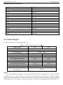
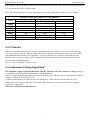
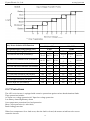
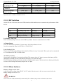
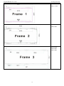
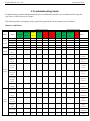
Yiyuan Electric Co., Ltd
www.yiyen.com
AP Series
Pure Sine Wave Inverter/Charger
User’s Manual
Version 1.0
Date: Feb 12th, 2012
Composer: Franklin Chu
1
Yiyuan Electric Co., Ltd
www.yiyen.com
Table of Contents
1. Important Safety Information ........................................................................................................................ 3
1-1. General Safety Precautions ......................................................................................................................... 3
1-2. Precautions When Working with Batteries ................................................................................................ 3
2. Introduction .................................................................................................................................................... 4
2-1. General Information ................................................................................................................................... 4
2-2. Application.................................................................................................................................................. 4
2.3 Mechanical Drawing .................................................................................................................................... 5
2-4. Features ....................................................................................................................................................... 6
2.5 Electrical Performance ................................................................................................................................. 7
2.5.1 Invert .................................................................................................................................................. 7
2.5.2 AC Charger ........................................................................................................................................ 7
2.5.3 Solar Charger* ................................................................................................................................... 9
2.5.4 Power Saver ..................................................................................................................................... 10
2.5.5 Transfer ............................................................................................................................................ 11
2.5.6 Automatic Voltage Regulation* ...................................................................................................... 11
2.5.7 Protections........................................................................................................................................ 12
2.5.8 Remote control ................................................................................................................................. 13
2.5.9 LED Indicator & LCD ..................................................................................................................... 13
2.5.10 Audible Alarm ............................................................................................................................... 14
2.5.11 FAN Operation............................................................................................................................... 14
2.5.12 DIP Switches .................................................................................................................................. 15
2.5.13 Other features ................................................................................................................................. 15
3 Installation..................................................................................................................................................... 17
3.1 Location .............................................................................................................................................. 17
3.2 Wiring recommendation ..................................................................................................................... 17
3.3 Install Flange ....................................................................................................................................... 17
4 Troubleshooting Guide ................................................................................................................................. 19
5 Warranty ....................................................................................................................................................... 20
2
Yiyuan Electric Co., Ltd
www.yiyen.com
1. Important Safety Information
WARNING! Before using the Inverter, you need to read and save the safety instructions.
1-1. General Safety Precautions
1-1-1.Do not expose the Inverter to rain, snow, spray, bilge or dust. To reduce risk of hazard, do not cover or
obstruct the ventilation openings. Do not install the Inverter in a zero-clearance compartment. Overheating
may result.
1-1-2. To avoid a risk of fire and electronic shock. Make sure that existing wiring is in good electrical
condition; and that wire size is not undersized. Do not operate the Inverter with damaged or substandard
wiring.
1-1-3. This equipment contains components which can produce arcs or sparks. To prevent fire or explosion
do not install in compartments containing batteries or flammable materials or in locations which require
ignition protected equipment. This includes any space containing gasoline-powered machinery, fuel tanks,
or joints, fittings, or other connection between components of the fuel system.
See Warranty for instructions on obtaining service.
1-1-4. Do not disassemble the Inverter/Charger. It contains no userserviceable parts. Attempting to service
the Inverter/Charger yourself may result in a risk of electrical shock or fire. Internal capacitors remain
charged after all power is disconnected.
1-1-5. To reduce the risk of electrical shock, disconnect both AC and DC power from the RV Series
Inverter/Charger before attempting any maintenance or cleaning. Turning off controls will not reduce this
risk
CAUTION: Equipment damage
The output side of the inverter’s AC wiring should at no time be connected to public power or a generator.
This condition is far worse than a short circuit. If the unit survives this condition, it will shut down until
corrections are made.
Installation should ensure that the inverter’s AC output is, at no time, connected to its AC input.
Warning: Limitations On Use
SPECIFICALLY, PLEASE NOTE THAT THE APC SERIES INVERTER/CHARGER SHOULD NOT BE
USED IN CONNECTION WITH LIFE SUPPORT SYSTEMS OR OTHER MEDICAL EQUIPMENT OR
DEVICES.
1-2. Precautions When Working with Batteries
1-2-1. If battery acid contacts skin or clothing, wash immediately with soap and water. If acid enters eye,
immediately flood eye with running cold water for at least 20 minutes and get medical attention
immediately.
1-2-2. Never smoke or allow a spark or flame in vicinity of battery or engine.
1-2-3. Do not drop a metal tool on the battery. The resulting spark or short-circuit on the battery of other
electrical part may cause an explosion.
1-2-4. Remove personal metal items such as rings, bracelets, necklaces, and watches when working with a
lead-acid battery. A lead-acid battery produces a short-circuit current high enough to weld a ring or the like
to metal, causing a severe burn.
1-2-5. To reduce the risk of injury, charge only deep-cycle lead acid, lead antimony, lead calcium gel cell,
absorbed mat, or NiCad/NiFe type rechargeable batteries. Other types of batteries may burst, causing
personal injury and damage.
3
Yiyuan Electric Co., Ltd
www.yiyen.com
2. Introduction
2-1. General Information
APC Series Pure Sine Wave Inverter is a combination of an inverter, battery charger and AC auto-transfer
switch into one complete system with a peak conversion efficiency of 88%.
It is packed with unique features and it is one of the most advanced inverter/chargers in the market today.
It features power factor corrected, sophisticated multi-stage charging and pure sine wave output with
unprecedentedly high surge capability to meet demanding power needs of inductive loads without
endangering the equipment.
For the regular model, when utility AC power cuts off(or falls out of acceptable range), the transfer relay is
de-energized and the load is automatically transferred to the Inverter output. Once the qualified AC utility is
restored, the relay is energized and the load is automatically reconnected to AC utility.
The APC Series Inverter is equipped with a powerful charger of up to 90Amp(depending on model).
The overload capacity is 300% of continuous output for up to 20 seconds to reliably support tools and
equipment longer
Another important feature is that the inverter can be easily customized to Battery priority via a DIP switch,
this helps to extract maximum power from battery in renewable energy systems.
Thus, the APC Series Pure Sine Wave Inverter is suitable for Renewable energy system,Utility, RV, Marin
and Emergency appliances.
To get the most out of the power inverter, it must be installed, used and maintained properly. Please read the
instructions in this manual before installing and operating.
2-2. Application
Power tools–circular saws, drills, grinders, sanders, buffers, weed and hedge trimmers, air compressors.
Office equipment – computers, printers, monitors, facsimile machines, scanners.
Household items – vacuum cleaners, fans, fluorescent and incandescent lights, shavers, sewing machines.
Kitchen appliances – coffee makers, blenders, ice markers, toasters.
Industrial equipment – metal halide lamp, high – pressure sodium lamp.
Home entertainment electronics – television, VCRs, video games, stereos, musical instruments, satellite
equipment.
4
Yiyuan Electric Co., Ltd
www.yiyen.com
2.3 Mechanical Drawing
5
Yiyuan Electric Co., Ltd
www.yiyen.com
2-4. Features
High overload ability up to 300% rated power(20 sec)
Low quiescent current, low power “ Power Saving Mode “ to conserve energy
3-step intelligent battery charging, PFC(Power Factor Correction) for charger
8 pre set battery type selector plus de-sulphation for totally flat batteries
Powerful charge rate up to 90Amp, selectable from 0%-100%
10 ms typical transfer time between battery and AC, guarantees power continuity
Smart remote control
15s delay before transfer when AC resumes, extra protection for loads when used with
generator
Allows start up and through power with depleted batteries
30A/40A through current ability
Multiple controlled cooling fan
Extensive protections against various harsh situations
13VDC battery recover point, dedicated for renewable energy systems
6
Yiyuan Electric Co., Ltd
www.yiyen.com
2.5 Electrical Performance
2.5.1 Invert
Topology
The APC inverter/charger is built according to the following topology.
Invert: Full Bridge Topology.
Charge: Isolate Boost Topology
The peak efficiency of APC series is 88%.
Overload Capacity
The APC series inverters have different overload capacities, making it ideal to handle demanding loads.
1 For 110%<Load<125%(±10%), no audible alarm in 14 minutes, beeps 0.5s every 1s in the 15th minute,
and Fault(Turn off) after the 15th minute.
2 For 125%<Load<150%(±10%), beeps 0.5s every 1s and Fault(Turn off) after the 1 minute.
3 For 300%≧Load>150%(±10%), beeps 0.5s every 1s and Fault(Turn off) after 20s.
2.5.2 AC Charger
APC Series is equipped with an active multistage battery charger.
The APC series inverter is with a strong charging current of 90Amp(for 3KW,12V), and the max charge
current can be adjusted from 0%-100% via a liner switch at the right of the battery type selector. The liner
switch can effectively reduce the max charging current to 20% of its peak.
Choosing “0” in the battery type selector will disable charging function.
There are mainly 3 stages:
Bulk Charging: This is the initial stage of charging. While Bulk Charging, the charger supplies the battery
with controlled constant current. The charger will remain in Bulk charge until the Absorption charge voltage
(determined by the Battery Type selection) is achieved.
Software timer will measure the time from A/C start until the battery charger reaches 0.3V below the boost
voltage, then take this time asT0 and T0×10 = T1.
Absorb Charging: This is the second charging stage and begins after the absorb voltage has been reached.
Absorb Charging provides the batteries with a constant voltage and reduces the DC charging current in order
to maintain the absorb voltage setting.
In this period, the inverter will start a T1 timer; the charger will keep the boost voltage in Boost CV mode
until the T1 timer has run out. Then drop the voltage down to the float voltage. The timer has a minimum
time of 1 hour and a maximum time of 12 hours.
Float Charging: The third charging stage occurs at the end of the Absorb Charging time. While Float
charging, the charge voltage is reduced to the fl oat charge voltage (determined by the Battery Type
7
Yiyuan Electric Co., Ltd
www.yiyen.com
selection*). In this stage, the batteries are kept fully charged and ready if needed by the inverter.
If the A/C is reconnected or the battery voltage drops below 12Vdc/24Vdc, the charger will reset the cycle
above.
If the charge maintains the float state for 10 days, the charger will deliberately reset the cycle to protect the
battery.
Battery type selector
Switch setting
0
1
2
3
4
5
6
7
8
9
Description
Charger Off
Gel USA
AGM 1
AGM 2
Sealed lead acid
Gel EURO
Open lead acid
Calcium
De sulphation
Not used
Boost / Vdc
Float / Vdc
14.0
14.1
14.6
14.4
14.4
14.8
15.1
15.5 (4 Hours then Off)
13.7
13.4
13.7
13.6
13.8
13.3
13.6
12Vdc Mode (*2 for 24Vdc ; *4 for 48Vdc)
De-sulphation
The de-sulphation cycle on switch position 8 is marked in red because this is a very dangerous setting if you
do not know what you are doing. Before ever attempting to use this cycle you must clearly understand what
it does and when and how you would use it.
What causes sulphation? This can occur with infrequent use of the batteries, or if the batteries have been left
discharged so low that they will not accept a charge. This cycle is a very high voltage charge cycle designed
to try to break down the sulphated crust that is preventing the plates taking a charge and thus allow the plates
to clean up and so accept charge once again.
Charging depleted batteries
The APC series inverter allows start up and through power with depleted batteries.
8
Yiyuan Electric Co., Ltd
www.yiyen.com
Charging current for each model
Model
1012E
1024E
1512E
1524E
2012E
2024E
2048E
3012E
3024E
3048E
4024E
4048E
5024E
5048E
6024E
6048E
Current
35+/-5A
20+/-5A
45+/-5A
25+/-5A
65+/-5A
30+/-5A
20+/-5A
85+/-5A
45+/-5A
30+/-5A
65+/-5A
35+/-5A
70+/-5A
40+/-5A
85+/-5A
55+/-5A
2.5.3 Solar Charger*
For APV series, there is a solar charger built in.
Table 1 Electrical Specifications @ 25℃
Rated Voltage
12V
24V
Rated Charge Current
40A
Rated Output Current
15A
Self Consumption
At idle < 10mA
Bulk Charge
14.5V(default)
29.0V(default)
①
Floating Charge
13.5V(default)
27.0V(default)
①
Equalization Charge
14.0V(default)
28.0V(default)
Over Charge Disconnection
14.8V
29.6V
Over Charge Recovery
13.6V
27.2V
①
Over Discharge Disconnection
10.8 V(default)
21.6V(default)
Over Discharge Reconnection
12.3V
24.6V
①
Temperature Compensation
-13.2mV/℃
-26.4mV/℃
Ambient Temperature
0-40℃(full load) 40-60℃(derating)
Terminal Size
#8AWG
(fine/single wire)
NOTE:
① The optional battery temperature sensor automatically adjusts the charging process of the controller
according to the type of the battery is selected by user through battery type selector. With the battery
temperature sensor installed, the controller will increase or decrease the battery charging voltage depending
on the temperature of the battery to optimize the charge to the battery and maintain optional performance of
9
Yiyuan Electric Co., Ltd
www.yiyen.com
the battery.
Maximum Power Point Tracking (MPPT) Function
Maximum Power Point Tracking, frequently referred to as MPPT, is an electronic system that operates the
Photovoltaic (PV) modules in a manner that allows the modules to produce all the power they are capable
of.
The PV-seeker Charge controller is a microprocessor-based system designed to implement the MPPT.
And it can increase charge current up to 30% or more compared to traditional charge controllers (see figure
1).
Figure 1 Current, Power vs. Voltage Characteristics
2.5.4 Power Saver
There are 2 different working status for APC
inverter: “Power On” and “Power Off”.
When power switch is in “Unit Off” position, the
inverter is powered off.
When power switch is in either of “Power Saver
Auto” or “Power Saver Off”, the inverter is
powered on.
Power saver function is to dedicated to conserve
battery power when AC power is not or little
required by the loads.
In this mode, the inverter pulses the AC output
looking for an AC load (i.e., electrical appliance).
Whenever an AC load (greater than 25 watts) is
turned on, the inverter recognizes the need for power and automatically starts inverting and output goes to
full voltage. When there is no load (or less than 25 watts) detected, the inverter automatically goes back into
search mode to minimize energy consumption from the battery bank.
In “Power saver on” mode, the inverter will draw power mainly in sensing moments, thus the idle
consumption is significantly reduced.
10
Yiyuan Electric Co., Ltd
www.yiyen.com
The inverter is factory defaulted to detect load for 250ms in every 30 seconds. This cycle can be customized
to 3 seconds thru the SW3 on DIP switch.
Note: The minimum power of load to take inverter out of sleep mode (Power Saver On) is 25 Watts.
Model
1000W
1500W
2000W
3000W
4000W
5000W
6000W
AnyPower Combi Series Idle Power Consumption
Power Saver Off
Power Saver Auto
Idle
3Secs(Max)
30Secs(MAX)
42W
16W
10W
48W
20W
10W
60W
25W
10W
72W
28W
12W
120W
45W
15W
135W
50W
18W
145W
55W
18W
2.5.5 Transfer
While in the Standby Mode, the AC input is continually monitored. Whenever AC power falls below the
VAC Trip voltage (154 VAC, default setting), the inverter automatically transfers back to the Invert Mode
with minimum interruption to your appliances - as long as the inverter is turned on. The transfer from
Standby mode to Inverter mode occurs in approximately 10 milliseconds. And it is the same time from
Inverter mode to Standby mode.
There is a 15-second delay from DC to AC.
2.5.6 Automatic Voltage Regulation*
The automatic voltage regulation function is only for APS Pure Sine Wave Inverter/ Charger which is
a combination of APC inverter and Automatic Voltage Regulator.
Instead of simply bypassing the input AC to power the loads, the APS series inverter stabilizes the input AC
voltage to a range of 230V/120V±10%.
Connected with batteries, the APS inverter will function as a UPS with max transfer time of 10 ms.
With all the unique features from the inverter and AVR, it brings you long-term trouble free operation
beyond your expectation.
APS Series AVR Function Introduction
11
Yiyuan Electric Co., Ltd
www.yiyen.com
Any-Power Solution Series
Any-Power Solution AVR Function
LV (NA/JPN)
HV (INTL)
0-160
0-300
Acceptable Input Voltage Range (Vac)
Nominal Input Voltages (Vac)
100
110
120
220
230
75/65
84/72
92/78
**
168/14
3
178/15
3
**
176/15
0
186/16
0
**
80/70
89/77
97/83
(C) Line 2nd boost threshold (On Boost)
**
**
(D) Line 2nd boost comeback (On normal)
**
**
**
**
**
**
(E) Line 1st boost threshold (On Boost)
90
99
108
198
207
216
(F) Line 1st boost comeback (On normal)
93
103
112
205
215
225
(G) Line buck comeback (On Normal)
106
118
128
235
246
256
(H) Line buck threshold (On Buck)
110
121
132
242
253
264
(I) Line high comeback (On Buck)
115
127
139
253
266
278
(J) Line high loss (On Battery)
120
132
144
263
276
288
(A) Line low loss N/W (On battery)
(B) Line Low comeback N/W (On Boost)
240
183/156
193/166
**
2.5.7 Protections
The APC series inverter is equipped with extensive protections against various harsh situations/faults.
These protections include:
AC Input over voltage protection/AC Input low voltage protection
Low battery alarm/High battery alarm
Over temperature protection/Over load protection
Short Circuit protection (1s after fault)
Back feeding protection
When Over temperature /Over load occur, after the fault is cleared, the master switch has to be reset to
restart the inverter.
12
Yiyuan Electric Co., Ltd
www.yiyen.com
The Low batter voltage trip point can be customized from defaulted value 10VDC to 10.5VDC thru the SW1
on DIP switch.
The inverter will go to Over temp protection when heat sink temp. ≥105ºC, and go to Fault (shutdown
Output) after 30 seconds. The switch has to be reset to activate the inverter.
The APC series Inverter is with back feeding protection which avoids presenting an AC voltage on the AC
input terminal in Invert mode.
After the reason for fault is cleared, the inverter has to be reset to start working.
2.5.8 Remote control
Apart from the switch panel on the front of the inverter, an
extra switch panel connected to the RJ11 port at the DC side of
the inverter thru a standard telephone cable can also control the
operation of the inverter.
If an extra switch panel is connected to the inverter via “remote
control port”, together with the panel on the inverter case, the
two panels will be connected and operated in parallel.
Whichever first switches from “Off” to “Power saver off” or
“Power saver on”, it will power the inverter on.
If the commands from the two panels conflict, the inverter will
accept command according to the following priority:
Power saver on> Power saver off> Power off
Only when both panels are turned to “Unit Off” position, the inverter will be powered off.
2.5.9 LED Indicator & LCD
SHORE POWER ON
INVERTER ON
FAST CHARGE
FLOAT CHARGE
OVER TEMP TRIP
OVER LOAD TRIP
GREEN LED lighting on AC Mode
GREEN LED lighting on Inverter Mode
Yellow LED lighting on Fast Charging Mode
GREEN LED lighting on Float Charging Mode
RED LED lighting on Over Temperature
RED LED lighting on Over Load
GREEN LED lighting on Power Saver Mode (Power
Saver Load ≦25W)
POWER SAVER ON
13
Yiyuan Electric Co., Ltd
www.yiyen.com
The Inverter can be customized into LCD type. The LCD will display the following content:
1 Greeting message of “Welcome to EYEN”
2 AC Status & Input Voltage
3 Output Voltage/Frequency and Battery voltage
“AC: abnormal” will be displayed when AC input is
not qualified.
4 Output Current( in percentage)
2.5.10 Audible Alarm
Inverter green LED Lighting, and the buzzer beep 0.5s every 5s.
Inverter green LED Lighting, and the buzzer beep 0.5s every 1s,
and Fault after 60s.
(1)110%<load<125%(±10%), No audible alarm in 14 minutes,
Beeps 0.5s every 1s in 15th minute and Fault after 15 minutes;
(2)125% <load<150%(±10%), Beeps 0.5s every 1s and Fault after 60s;
(3)Load>150%(±10%), Beeps 0.5s every 1s and Fault after 20s;
Heat sink temp. ≥105ºC, Over temp red LED Lighting, beeps 0.5s every
1s;
Battery Voltage Low
Battery Voltage High
Invert Mode Over-Load
Over Temperature
2.5.11 FAN Operation
For 1-3KW, there is one multiple controlled DC fan which starts to work according to the following logics.
For 4-6KW, there is one multiple controlled DC fan and one AC fan. The DC fan will work in the same
way as the one on 1-3KW, while the AC fan will work once there is AC output from the inverter.
So when the inverter is in power saver mode, the AC fan will work from time to time in response to the
pulse sent by the inverter in power saver mode.
The Operation of DC fan at the DC terminal side is controlled in the following logic:
Condition
Enter Condition
Leave condition
14
Speed
Yiyuan Electric Co., Ltd
www.yiyen.com
T ≥ 85℃
T < 80℃
I > 50%Max
I ≤ 40%Max
Load ≥ 50%
Load ≤ 40%
T < 85 ℃
T ≥ 85℃
I ≤ 50%Max
I > 50%Max
Load < 50%
Load ≥ 50%
HEAT SINK
TEMPERATURE
CHARGER
CURRENT
LOAD Percentage
(INV MODE)
50%
100%
50%
100%
50%
100%
Fan noise level <60db at a distance of 1m
2.5.12 DIP Switches
On the DC end of inverter, there are 4 DIP switches which enable users to customize the performance of the
device.
Switch NO
SW1
SW2
SW3
SW4
Switch Function
Low Battery Trip Volt
AC Input Range
Load Sensing Cycle
Battery/AC Priority
Position: 0
10.0VDC
184-253VAC
30 seconds
Utility Priority
Position: 1
10.5VDC
154-253VAC
3 seconds
Battery Priority
Low Battery Trip Volt:
The Low Battery Trip Volt is set at 10.0VDC by default. It can be customized to 10.5VDC..
AC Input Range:
There are different acceptable AC input ranges for different kinds of loads.
It can be customized from 184-253VAC to 154-253VAC.
Load Sensing Cycle:
The inverter is factory defaulted to detect load for 250ms in every 30 seconds. This cycle can be customized
to 3 seconds thru the SW3 on DIP switch.
AC/Battery Priority:
Our inverter is designed AC priority by default. This means, when AC input is present, the battery will be
charged first, and the inverter will transfer the input AC to power the load.
The AC Priority and Battery Priority switch is available upon request. When you choose battery priority, the
inverter will inverting from battery despite the AC input.
2.5.13 Other features
Battery voltage recover start
After low battery voltage shut off(10V for 12V model), the inverter is able to restore to work after the
battery voltage recovers to 13V.
WARNING
Never leave the loads unattended, some loads (like a Heater) may cause accident in such cases.
15
Yiyuan Electric Co., Ltd
www.yiyen.com
It is better to shut everything down after low voltage trip than to leave your load in the risk of fire. Nobody
wants to return home, finding house surrounded by fire trucks, and naughty neighborhood kids toasting hot
dogs against his house.
16
Yiyuan Electric Co., Ltd
www.yiyen.com
3 Installation
3.1 Location
Follow all the local regulations to install the inverter.
Please install the equipment in a location of Dry, Clean, Cool with good ventilation.
Working temperature : ‐10℃‐40℃
Storage temperature : ‐40‐70℃
Relative Humidity : 0%‐95%,non-condensing
Cooling : Forced air
3.2 Wiring recommendation
It is suggested the battery bank be kept as close as possible to the inverter. The following able is a suggested
wiring option for 1 meter DC cable.
Please find the following minimum wire size. In case of DC cable longer than 1m, please increase the cross section of
cable to reduce the loss.
Power
1KW
1KW
1.5KW
1.5KW
2KW
2KW
2KW
3KW
3KW
3KW
4KW
4KW
5KW
5KW
6KW
6KW
DC Input voltage
12V
24V
12V
24V
12V
24V
48V
12V
24V
48V
24V
48V
24V
48V
24V
48V
Wire Gage
AWG 8
AWG 8
AWG 8
AWG 8
AWG 8
AWG 8
AWG 8
AWG 8
AWG 8
AWG 8
AWG 8
AWG 8
AWG 8
AWG 8
AWG 8
AWG 8
3.3 Install Flange
17
Strings
3
2
3
2
5
3
2
7
4
2
5
2
6
3
7
4
Yiyuan Electric Co., Ltd
www.yiyen.com
APC1-1.5KW
APS1-1.5KW
APC2-3KW
APS2-3KW
APC4-6KW
APS4-6KW
APS1-3KW
18
Yiyuan Electric Co., Ltd
www.yiyen.com
4 Troubleshooting Guide
Troubleshooting contains information about how to troubleshoot possible error conditions while using the
Any Power Combi Inverter & Charger.
The following chart is designed to help you quickly pinpoint the most common inverter failures.
Indicator and Buzzer
Indicator on top cover
SHORE
Status
Item
POWER
ON
INVERT
FAST
FLOAT
ER ON
CHG
CHG
LED on Remote Switch
OVER
OVER
POWER
TEMP
LOAD
SAVER
TRIP
TRIP
ON
BATT
INVERTE
CHG
R
Alarm
Buzzer
CC
√
×
√
×
×
×
×
√
×
×
×
Line
CV
√
×
√, blink
×
×
×
×
√
×
×
×
Mode
Float
√
×
×
√
×
×
×
√
×
×
×
Standby
√
×
×
×
×
×
×
×
×
×
×
Inverter On
×
√
×
×
×
×
×
×
√
×
×
×
×
×
×
×
×
√
×
×
×
×
×
√
×
×
×
×
×
×
√
√
×
√
×
×
×
×
×
×
√
√
Inverter
Mode
Power
Saver
Battery
Low
Battery
High
Overload
On Invert
Mode
×
√
×
×
×
√
×
×
√
√
×
√
×
×
√
×
×
×
√
√
√
×
√
×
√
×
×
√
×
√
√
×
√
×
×
×
×
√
×
√
×
×
×
×
×
×
×
×
×
×
×
√
×
×
×
×
×
×
√
×
×
×
×
×
×
√
×
×
×
×
×
×
×
×
×
√
×
×
×
√
Over-Temp
×
×
×
×
√
×
×
×
×
×
Over
×
×
√
×
×
×
×
√
×
×
Mode
Over-Temp
On Line
Mode
Over
Charge
Fan Lock
Battery
High
Inverter
Fault
Mode
Mode
Overload
Output
Short
Beep 0.5s
every 1s
“Audible
alarm”
Over-Temp
On Invert
every 5s
Refer to
Mode
Inverter
Beep 0.5s
19
Beep 0.5s
every 1s
Beep 0.5s
every 1s
Beep 0.5s
every 1s
Beep
continuous
Beep
continuous
Beep
continuous
Beep
continuous
Beep
continuous
Beep
Yiyuan Electric Co., Ltd
www.yiyen.com
Charge
Back Feed
Short
continuous
×
×
Symptom
Inverter will not turn on during
initial power up.
No AC output voltage and no
indicator lights ON.
AC output voltage is low and the
inverter turns loads OFF in a short
time.
Charger is inoperative and unit
will not accept AC.
Charger is supplying a lower
charge rate.
Charger turns OFF while charging
from a generator.
Sensitive loads turn off
temporarily when transferring
between grid and inverting.
Noise from Transformer/case
×
×
×
×
×
×
×
×
Beep
continuous
Possible Cause
Batteries are not connected, loose
battery-side connections.
Recommended Solution
Check the batteries and cable
connections.
Low battery voltage.
Inverter has been manually
transitioned to OFF mode.
Low battery.
Charge the battery.
Press the switch to Power saver on
or Power saver off position.
Check the condition of the
batteries and recharge if possible.
AC voltage has dropped
out-of-tolerance
Charger controls are improperly
set.
Check the AC voltage for proper
voltage and frequency.
Refer to the section on adjusting
the “Charger Rate”.
Low AC input voltage.
Source qualified AC power..
Loose battery or AC input
connections.
High AC input voltages from the
generator.
Check all DC /AC connections.
Inverter's Low voltage trip voltage
may be too low to sustain
certain loads.
Applying specific loads such as
hair drier
5 Warranty
We offer 1 year limited warranty.
20
Load the generator down with a
heavy load.
Turn the generator output voltage
down.
Choose narrow AC voltage in the
DIP switch, or Install a UPS if
possible.
Remove the loads


![RessqM, Enhanced Version of RESSQ [Javandel et al., 1984]](http://vs1.manualzilla.com/store/data/005674408_1-e8a4b9f66c80cdc83d847a710e5b4b1f-150x150.png)