1
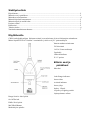
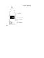
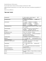
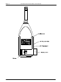
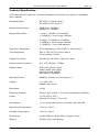
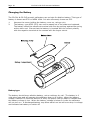
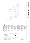
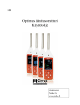
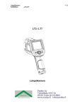
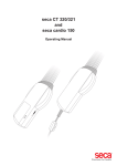
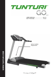
Äänitasomittarin CR 306
Käyttöohje
Markkinointi: Pietiko Oy
www.pietiko.fi
02 2524402
Sisällysluettelo
Käyttöönotto.........................................................................................................................................2
Mittarin osat ja painikkeet....................................................................................................................2
Mittauksen suorittaminen.....................................................................................................................4
Mittarin käytössä huomattavaa.............................................................................................................5
Mittarin näyttö ja merkkivalot..............................................................................................................5
Pariston vaihto......................................................................................................................................5
Kalibrointi.............................................................................................................................................5
Tekniset tiedot.......................................................................................................................................6
Vaatimuksenmukaisuusvakuutus..........................................................................................................7
Käyttöönotto
CR306 on helpokäyttöinen äänitason mittari ja on tarkoitettu yleiseen äänitasojen mittaukseen.
Mittari täyttää IEC61672 luokka 2 vaatimukset ja siinä on A ja C painotuskäyrät.
Mittarin mukana toimitetaan
CR:306 mittari
UA:236 50 mm tuulisuoja
Käyttöohje
Kalibrointitodistus
1X 9 V paristo
Mittarin osat ja
painikkeet
Mikrofoni
Under Range indicator:
Alueen alitus
Overload indicator
Alueen ylitys
Display: Näyttö
Frequency weighting switch
Taajuuspainotus valinta
Range Switch: Alue kytkin
On Off Switch
Päälle/ Pois kytkin
MAXHold Button
Makximi/pito painike
Calbration Adjustment
Kalibrointiruuvi
Serial Number: Sarjanumero
AC output: AC-lähtö
DC Power input
Jännitesyöttö
Battery Cover : pariston kansi
Mittauksen suorittaminen
Ennen mittausten aloittamista varmista, että mittarissa on kunnossa olevat paristot.
Kytke mittari päälle kääntämällä Päälle/Pois kytkin F asentoon
OFF : mittari on pois päältä
F
mittari on kytketty nopeaan mittaukseen lyhyellä aikavakiolla
Odota noin 10 s ennen varsinaista mittausta.
Varmista, että mittari on kalibroitu
Valitse tarvittava taajuuspainotus A/C kytkimellä
A: A-painotus (dB(A)
C : C-painotus dB(C)
Valitse sopiva mittausalue H/L kytkimellä
L: alempi alue (max 100 dBA)
H: ylempi alue(yli 65 dBA)
Jos haluat mitat maksimiäänentasoja paina MAXHOLD painiketta vähintään 0.5 s. Kun vapautat
painikkeen HOLD teksti näkyy näytöllä ylhäällä vasemmalla. Mittari näyttää nyt suurinta mitattua
äänentasoa.
Kytke tämä toiminto pais painamalla HOLD uudelleen tai kytke mittari pois päältä.
Mittarin käytössä huomattavaa
● Odota 10s mittarin käynnistyksen jälkeen ennen mittauksen aloittamista tai kalibrointia
● Tarkista paristojen kunto ennen mittausta. CR 306 seuraa paristojen tasoa jatkuvasti
mittauksen aikana.
● Tarkista, että MAXHOLD toiminto on kytketty pois päältä kun se ei ole käytössä.
● Kalibroi mittari mahdollisimman usein
● Poista paristo mittarista, kun sitä ei käytetä pitkään aikaan
Mittarin näyttö ja merkkivalot
Mittarin näytöllä on merkkitekstejä seuraavasti:
LOWBAT
Pariston kapasiteetti riittämätön, vaihda paristot
MAXHOLD näyttö näyttää maksimiarvoa, poistu painamalla MAXHOLD
Näytön päällä on seuraavat merkkivalot
Vihreä valo
Äänitaso on alle mittausalueen. Siirrä L/H kytkin asentton L
Punainen valo Äänitaso on yli alueeen. Siirrä L/H kytkin asentoon H
Pariston vaihto
Varmista, että mittari on pois päältä
Avaa paristokotelo painamalla kannen vasenta puolta ja työntämällä oikealle
Vaihda uusi paristo , tyyppiä IEC6F22 (PP3)
Aseta pariston kansi paikoilleen
Kalibrointi
Paras mittaustulos saavutetaan kaliboimalla mittari aina ennen käyttöä j akäytön jälkeen. Näin
varmistetaan mittauksen oikeellisuus.
Mittari kalibroidaan akustisesti käyttämällä ulkoista verailuäänilähdettä, esim kalibraattoria CR:514
Kalibraattori antaa Äänitason 94 dB(+/-0.3 db) taajuudella 1 kHz
Kalibroinnin suoritus
Varmista paristojen kunto
Varmista, että kalibraatori on kunnolla mikrofonikapselin ympärillä
Kytke mittari päälle seuraavin asetuksin
OFF/F asennossa A, L/H asennossa L ja A/C asennossa A
Varmista, että MAXHOLD ei ole tominnassa
Kytka kalibraattori 94 db asentoon
Kierrä kalibrointiruuvia hitaasti kunnes mittarissa on lukema 93,7 dBA.
(Mikrofonikapselin painekorjaus on 0.3 dBA. Tämän vuoksi mittari on säädettävä näyttämään 93,7
dBA)
Mittari on nyt kalibroitu
Tekniset tiedot
Standardit:
IEC 61672-1:2002 Class 2
60651:1979 Type 2 I
Mittausalueet:
35dB(A) to 130dB(A)
130dB(C)
Aluetiedot:
L (Low) = 35dB(A) to 100dB(A)
>
100dB(A) = ylialue
H (High) =
65dB(A) to 130dB(A)
< 65dB(A) =
alialue
> 130dB(A) = ylialue
Taajuuspainotus
A & C-painotus IEC 61672-1:2002 Class
2 mukaan
Aikasuodatus
Nopea IEC 61672-1:2002 Class 2
mukaan
aikavakio 125mS
Näyttö:
Mittaustoiminnot:
IEC
40dB(C) to
Normal (Äänitaso, Maximum Hold
LAF, LCF, LAFMax, LCFMax
Näyttötekstit:
Ylialue (Vihreä)
Alialue (Punainen)
Maximum Hold (HOLD)
paristovaroitusy (LOWBAT)
Vertailupiste:
94dB(A), 1000Hz on Low Range (L)
Näyttö:
3 ½ digit LCD
Lukematarkkuus:
0.1dB
virkistystaajuus 1Hz
Sähköinen lähtöliityntä:
AC Out Max output = 2V, output
impedance 600Ohm
Teholähde:
1 x 9V (6F22, PP3)
7V .. 10V
Microfoni:
½” pre-polarised electret condenser
type MK:268
Toimintalämpötila:
-10°C to +50°C
Varastointilämpötila:
-20°C to +60°C
mitat:
paino
Ulkoien DC ,
pituus 248mm, leveys 66mm, korkeus
30mm
227g (8oz) paristolla
Vaatimuksenmukaisuusvakuutus
CR:306 Sound Level Meter User Manual
User Manual for the
CR:306 Sound Level Meter
This manual, the software to which it relates, the
program code and drawings are all:
© Copyright Cirrus Research plc 1989-2007
Page 1
Page 2
CR:306 Sound Level Meter User Manual
The content of this manual, any illustrations, technical information and descriptions within this document
were correct at the time of going to print. Cirrus Research plc reserves the right to make any changes
necessary, without notice, in line with the policy of continuing product development and improvement.
No part of this publication may be duplicated, reprinted, stored in a data processing system or transmitted
by electronic, mechanical, photographic or other means, or recorded, translated, edited, abridged or
expanded without the prior written consent of Cirrus Research plc.
No liability is accepted for any inaccuracies or omissions in this manual, although due care has been taken
to ensure that it is complete and as accurate as possible.
Accessories supplied by Cirrus Research plc have been designed for use with the instrumentation
manufactured by Cirrus Research plc. No responsibility is accepted for damage caused by the use of any
other parts or accessories.
In order to take account of a policy of continual development, Cirrus Research plc reserves the right to
change any of the information contained in this publication without prior notice.
Produced by Cirrus Research plc, Acoustic House, Bridlington Road, Hunmanby, North Yorkshire, YO14
0PH, United Kingdom.
© Copyright Cirrus Research plc 2007
Reference Number 04/07/CR:306/01
Document Printing Date Tuesday, 24 April 2007
CR:306 Sound Level Meter User Manual
Page 3
Overview. ..................................................................................................................... 4
First time use. .............................................................................................................. 4
CR:306 Instrument Check List ...................................................................................... 4
Instrument Controls ..................................................................................................... 5
Taking Measurements .................................................................................................. 7
Fundamental precautions. ............................................................................................ 7
Display and Indicators.................................................................................................. 8
Display ...................................................................................................................... 8
Indicator.................................................................................................................... 8
Fitting a New Battery ................................................................................................... 9
Field Calibration ......................................................................................................... 10
Calibration Procedure................................................................................................. 10
Technical Specification ............................................................................................... 11
Appendix 1 - CE Declaration of Conformity ................................................................. 12
Acoustic Calibrator Information ................................................................................. 13
Warranty Information. ................................................................................................23
Cirrus Research Offices ...............................................................................................24
Page 4
CR:306 Sound Level Meter User Manual
Overview.
Thank you for purchasing the CR:306 sound level meter from Cirrus Research plc. This
entry level meter is designed to be quick and simple to use when taking basic sound
measurements and we are sure it will meet your requirements.
The CR:306 is a general purpose digital sound level meter which meets the full
requirements of IEC 61672 to Class 2. The instrument has 'F' (Fast) response and has
both 'A' and 'C' frequency weightings. In addition facilities are provided to hold the
maximum reading occurring throughout the measurement period.
First time use.
The CR:306 should be inspected for any signs of damage and also to ensure that all
relevant accessories are present. Your CR:306 will have been supplied either as a single
unit or as part of a full measurement kit, CK:306.
CR:306 Instrument Check List
The CR:306 Sound Level Meter is supplied with the following accessories as standard:
CR:306 Class 2 Sound Level Meter
UA:236 50mm wind shield
Calibration Screwdriver
User Manual
Certificate of Calibration
1 x 9V Battery
The CR:306 Sound Level Meter can also be supplied as a complete measurement kit,
the CK:306, which includes a CR:514 Class 2 Acoustic Calibrator and a CP:65 carrying
pouch.
For further details of the options and accessories for the CR:306 Sound Level Meter,
please contact your local representative.
CR:306 Sound Level Meter User Manual
Instrument Controls
Page 5
Page 6
CR:306 Sound Level Meter User Manual
CR:306 Sound Level Meter User Manual
Page 7
Taking Measurements
Before taking measurements, ensure the instrument has a new or highly charged
battery fitted. The instrument is supplied with a battery but it is not fitted for transit.
See page 9 for details of fitting and changing the battery.
Turn the instrument on by moving the OFF/F slide switch to the F position:
> OFF
>F
= Instrument is powered off.
= Fast Time Weighting
Allow the instrument to settle for 10 seconds before calibrating or taking
measurements.
Ensure the instrument is calibrated (see page 10 for details of calibration)
Select the required Frequency Weighting using the A/C slide switch:
>A
>C
= A-Weighting or dB(A)
= C-Weighting or dB(C)
Select the most appropriate range for the acoustic environment using the H/L slide
switch:
>L
>H
= Low Range (suitable for levels up to 100dBA)
= High Range (suitable for levels over 65dBA)
If the maximum exceeded level is required then press the MAX HOLD button for at least
½ second.
Once released the text HOLD is illuminated in the top left of the instrument display. In
this mode the highest measured sound pressure level is displayed.
To turn off the maximum hold facility either press the MAX HOLD button again or turn
the unit off.
Fundamental precautions.
This section contains some simple points that should be considered when using the
CR:306 instrument:
a)
Allow the instrument to settle for 10 seconds after switching on before calibrating
or taking measurements.
b)
Always check the battery before and after each measurement. The CR:306
monitors the battery continuously while operating.
c)
Ensure that the white MAX HOLD function is turned off when not required. If this
is not done, the display will freeze the last reading and the word HOLD will be
displayed on the top left of the LCD.
CR:306 Sound Level Meter User Manual
Page 8
d)
Wherever possible, always check the instrument calibration before and after each
measurement.
e)
Whenever the instrument is not to be used for a long period of time (> one
month) then remove the battery completely. This action will prevent leakage
damage.
Display and Indicators
Display
The LCD display of the CR:306 is scaled in decibels, either 'A' or 'C' weighted,
depending on the position of the A/C slide switch.
There are indicators in the display as follows:Function
Indicator
Cause and Possible Action
Low Battery
LOWBAT
Battery capacity low, replace battery
Maximum Hold
MAX HOLD
The display is MAX, push MAX HOLD to reset
Indicator
There are also two status indications above the instrument display, these have the
following functions:
Function
Indication
Cause and Possible Action
Under Range
Green Light
The sound level is below the current
measurement range. Move the L/H slide to the L
position.
Overload
Red Light
The sound level is above the current
measurement range. Move the L/H slide switch
to the H position.
CR:306 Sound Level Meter User Manual
Page 9
Fitting a New Battery
1. Ensure the instrument is turned off before removing the battery cover.
2. Remove the battery cover.
3. The battery is made accessible by pressing the left hand side of the battery
cover down slightly and then sliding it to the right. The spent battery can then be
removed and disposed of safely.
4. A new battery, IEC 6F22 (NEDA 1604, PP3) can then be fitted. The battery can
only be fitted in one orientation.
5. Replace the battery cover by sliding it back into place from right to left.
Page 10
CR:306 Sound Level Meter User Manual
Field Calibration
It is vital that the calibration of ANY sound level meter is checked before and after each
measurement. If this is done, it is reasonable to assume that the calibration during the
measurement was correct.
If this is NOT done, you will not subsequently be able to be certain that the instrument
calibration was correct and you can never be certain the sound level was as measured.
This process is commonly referred to as field calibration.
The sound level meter is calibrated acoustically using an external reference, e.g the
Sound Level Calibrator CR:514, which is placed over the microphone. The calibrator
generates a stabilised Sound Pressure Level of 94dB (+- 0.3dB) at a frequency of 1kHz.
Calibration Procedure
1. Ensure the batteries are fitted correctly and have sufficient power left.
2. Ensure the MK:268 microphone capsule is fitted correctly
3. Turn the instrument on with the following settings:
OFF/F in the A position
L/H in the L position
A/C in the A position
(This relates to Fast Time Weighting, Low Measurement Range and dB(A)
Frequency)
4. Ensure the MAX HOLD function is not active. (The word HOLD is not displayed
in the top left hand corner of the instrument display)
5. Attach the acoustic calibrator and turn it onto the 94dB output setting. An
acoustic calibrator such as the CR:514 is suitable.
6. Using the provided calibration screwdriver, slowly adjust the CAL
potentiometer until the instrument display reads 93.7dBA. (Turning the CAL
potentiometer clockwise increases the displayed level whereas anti-clockwise
reduces the displayed level)
Note: Although the CR:514 Acoustic Calibrator has an output of 94dB, the
pressure correction of the MK:268 microphone capsule is 0.3dBA. For this reason
the CR:306 must be adjusted to give a reading of 93.7dBA.
7. The instrument is now calibrated.
For details of the operation of the CR:514 and CR:515 Acoustic Calibrators, please refer
to the information contained at the back of this manual.
CR:306 Sound Level Meter User Manual
Page 11
Technical Specification
A full technical user manual, including mandated rating plate information is available
upon request.
Standardisation:
IEC 61672-1:2002 Class 2
IEC 60651:1979 Type 2 I
Measurement Range:
35dB(A) to 130dB(A)
40dB(C) to 130dB(C)
Range Information:
L (Low) = 35dB(A) to 100dB(A)
> 100dB(A) = over range indicator
H (High) = 65dB(A) to 130dB(A)
< 65dB(A) = down range indicator
> 130dB(A) = over load indicator
Frequency Weighting:
A & C-Weighting to IEC 61672-1:2002 Class 2
Time Weighting:
Fast to IEC 61672-1:2002 Class 2
Time constant 125mS
Display Functions:
Normal (Sound Level), Maximum Hold
Measurement Functions:
LAF, LCF, LAFMax, LCFMax
Display Flags:
Over Load (Green Light)
Under range (Red Light)
Maximum Hold (HOLD)
Low battery (LOWBAT)
Reference Point:
94dB(A), 1000Hz on Low Range (L)
Display:
3 ½ digit LCD
Update rate of 1Hz
Resolution:
0.1dB
Electrical Outputs:
AC Out Max output = 2V, output impedance 600Ohm
Power:
1 x 9V (6F22, PP3)
External DC Power, 7V to 10V
Microphone:
½” pre-polarised electret condenser type MK:268
Operating Temperature:
-10°C to +50°C
Storage Temperature:
-20°C to +60°C
Dimensions:
Length 248mm, Width 66mm, Depth 30mm
Weight:
227gms (8oz) with battery
CR:306 Sound Level Meter User Manual
Page 12
Appendix 1 - CE Declaration of Conformity
Cirrus Research plc Hunmanby UK
CE Certificate of Conformity
Manufacturer:
Cirrus Research plc
Acoustic House, Bridlington Road
Hunmanby, North Yorkshire, YO14 0PH
United Kingdom
Telephone +44 1723 891655
Equipment Description
The following equipment manufactured after 1st January 2007:
CR:306 Sound Level Meter
Along with their standard accessories
According to EMC Directives 89/336/EEC and 93/98/EEC
meet the following standards
EN 61000-6-3 (2001)
EMC : Generic emission standard for residential, commercial and light industrial
environments.
EN 61000-6-1 (2001)
EMC : Generic immunity standard for residential, commercial and light industrial
environments.
Signed
S. O′Rourke
Director
Dated 1st January 2007
CR:514 & CR:515 Acoustic Calibrator
CR:514 & CR:515
Acoustic Calibrator
User Manual
This manual, the software to which it relates, the
program code and drawings are all:
© Copyright Cirrus Research plc 1989-2007
Page 13
Page 14
CR:514 & CR:515 Acoustic Calibrator
The content of this manual, any illustrations, technical information and descriptions within this document
were correct at the time of going to print. Cirrus Research plc reserves the right to make any changes
necessary, without notice, in line with the policy of continuing product development and improvement.
No part of this publication may be duplicated, reprinted, stored in a data processing system or transmitted
by electronic, mechanical, photographic or other means, or recorded, translated, edited, abridged or
expanded without the prior written consent of Cirrus Research plc.
No liability is accepted for any inaccuracies or omissions in this manual, although due care has been taken
to ensure that is it complete and accurate as possible.
Accessories supplied by Cirrus Research plc have been designed for use with the instrumentation
manufactured by Cirrus Research plc. No responsibility is accepted for damage caused by the use of any
other parts or accessories.
In order to take account of a policy of continual development, Cirrus Research plc reserves the right to
change any of the information contained in this publication without prior notice.
Produced by Cirrus Research plc, Acoustic House, Bridlington Road, Hunmanby, North Yorkshire, YO14
0PH, United Kingdom.
© Copyright Cirrus Research plc 2007
Reference Number 11/06/CR514&515/01
Document Printing Date Tuesday, 24 April 2007
CR:514 & CR:515 Acoustic Calibrator
Page 15
Operation. .................................................................................................................. 16
Switching on the Calibrator......................................................................................... 16
Permanent-on Mode ..............................................................................................................16
Calibrating a Sound Level Meter. ................................................................................. 17
Background Noise ..................................................................................................... 17
Stabilisation ............................................................................................................. 17
Changing the Battery.................................................................................................. 18
Battery type. ............................................................................................................ 18
Specification............................................................................................................... 19
Appendix 1 – Technical Information ........................................................................... 20
Appendix 2 – Free Field Correction ............................................................................. 21
Microphone Correction Values .................................................................................................21
Example ..............................................................................................................................21
Appendix 3 - CE Declaration of Conformity ................................................................. 22
Equipment Description ............................................................................................... 22
Page 16
CR:514 & CR:515 Acoustic Calibrator
Operation.
Switching on the Calibrator
Press the Power Button on the end of the Calibrator to switch the unit on. The Indicator
will illuminate to show that the unit is operating.
The calibrator will automatically switch off after 5 minutes to preserve battery power.
To switch off the calibrator manually, press the power button again and the indicator
will extinguish to show that the unit is switched off.
Permanent-on Mode
For some applications there may be a need to have the calibrator switched on
continuously. To allow for this, the calibrator can be turned on by pressing and holding
the power button for three seconds.
Release the button and the indicator will flash to show that the unit is in permanent-on
mode. Press the power button to switch off the calibrator.
CR:514 & CR:515 Acoustic Calibrator
Page 17
Calibrating a Sound Level Meter.
Push the microphone of the Sound Level Meter into the cavity at the end of the
calibrator. Ensure the microphone is fully inserted into the cavity and is past the ‘O’ ring
seals. The microphone should be parallel to the body of the calibrator. Also ensure that
the small bleed-hole next to the microphone cavity is not blocked as this could cause
damage to the microphone.
Most modern Sound Level Meters have electronic calibration with the level adjusted
automatically. Adjust the Sound Level Meter to the correct level where applicable.
When correcting the value generated by the calibrator a correction for the type of
microphone capsule may need to be applied (see Appendix 2)
Background Noise
In order for the calibrator to operate as intended, the ambient acoustic noise level
should be no greater than 80dBA.
Stabilisation
In order for the sound pressure level and frequency to stabilise after switching the
calibrator on when coupled to a microphone, a period of at least 3 seconds should be
allowed before performing a calibration.
Page 18
CR:514 & CR:515 Acoustic Calibrator
Changing the Battery
The CR:514 & CR:515 acoustic calibrators use a single 9v alkaline battery. This type of
battery is known as 6F22 or NEDA 1604. It is also commonly known as PP3.
1.
2.
Unscrew the screw holding the battery cover on, using a coin.
The battery, type 6F22 (PP3) can now be eased out of its holder and replaced.
The battery should be eased out terminal side first by pushing against the spring
at the other end. Ensure that the battery is inserted with the correct polarity
with the negative terminal at the contact with the larger cutout.
Battery type.
The battery should be an alkaline battery, not an ordinary dry cell. The battery is 9
volts when new and will operate the calibrator down to 6.4 volts. When the battery
voltage is below 6.6 volts but above 6.4 volts, the power LED will flash to indicate that
the battery voltage is low. When the battery voltage is below 6.4 volts the calibrator
will not turn on. A discharged battery may allow switch-on but will soon drop in voltage
and indicate low battery or switch off.
CR:514 & CR:515 Acoustic Calibrator
Page 19
Specification.
Frequency
1kHz ± 1%
Sound Level
94dB re 20μPa
Standardisation
CR:514 - IEC 60942:2003 Class 2
CR:515 - IEC 60942:2003 Class 1
Distortion
Less than 2%
Operating Humidity
25 to 90% Relative Humidity
Operating Static Pressure
65 kPa to 108kPa
Operating Temperature
-10oC to +50oC
Storing Temperature
-20oC to +60oC
Effective Volume
6.19 cm3 ± 0.2 cm3
Cavity Diameter
0.525 inch
Battery
1 x 9v 6F22 (Neda 1604)
Battery Life
Approx 15 Hours Continuous Use
Battery Voltage
9v Nominal (10v Maximum, 6.4v Minimum)
Weight with Battery
185g
Dimensions
135mm x Ø48mm
Page 20
CR:514 & CR:515 Acoustic Calibrator
Appendix 1 – Technical Information
The normal mode of operation of the calibrator is with the unit switched on.
When the LED indicates the unit is switched on this produces the greatest radio
frequency emissions.
The calibrator continues to function after exposure to contact discharges up to 4kV and
air discharges up to 8kV, for both positive and negative voltages relative to earth
ground.
The calibrator conforms to IEC 60942:2003 for a modulated root-mean-square
electromagnetic field strength of 10 V/m.
The maximum susceptibility to power and radio frequency fields is with the cavity facing
away from the emitter with the battery compartment facing the table, the antenna
polarisation horizontal and the calibrator switched on.
CR:514 & CR:515 Acoustic Calibrator
Page 21
Appendix 2 – Free Field Correction
When calibrating a microphone which is to be used for free field measurements, a small
correction may be necessary to compensate for the difference between the
microphone's free field response at 'zero degrees' or 'head-on' incidence and the
pressure level generated by the calibrator.
The correction is typically -0.3dB for ½ inch microphones (making the effective
calibration level 93.7dB).
The table below shows the correction values for the standard microphones of Cirrus
Research plc.
Calibration corrections are listed below for the Cirrus Research plc ½" Capsules and
three microphone capsules commonly used in Calibration Laboratories:
Microphone Correction Values
Microphone Type
Calibration Correction
Effective Calibration Level
MK:202
MK:215
MK:216
MK:226
MK:224
-0.3dB
-0.3dB
-0.3dB
-0.3dB
-0.3dB
93.7
93.7
93.7
93.7
93.7
B&K 4134
B&K 4180
B&K 4192
0dB
0dB
0dB
94.0 dB
94.0 dB
94.0 dB
dB
dB
dB
dB
dB
Example
An example of the procedure used to calculate the value for an MK:224 microphone is
shown below :
Level = 94.0dB + Microphone Correction
Level = 94.0dB + ( -0.3dB)
Level = 93.7dB
Different microphones will have different correction values. Please check the operation
manual for the Sound Level Meter or microphone concerned for details.
CR:514 & CR:515 Acoustic Calibrator
Page 22
Appendix 3 - CE Declaration of Conformity
Cirrus Research plc Hunmanby UK
CE Certificate of Conformity
Manufacturer:
Cirrus Research plc
Acoustic House, Bridlington Road
Hunmanby, North Yorkshire, YO14 0PH
United Kingdom
Telephone +44 1723 891655
Equipment Description
The following equipment manufactured after 1st January 2007:
CR:514 Acoustic Calibrator
CR:515 Acoustic Calibrator
Along with their standard accessories
According to EMC Directives 89/336/EEC and 93/98/EEC
meet the following standards
EN 61000-6-3 (2001)
EMC : Generic emission standard for residential, commercial and light industrial
environments.
EN 61000-6-1 (2001)
EMC : Generic immunity standard for residential, commercial and light industrial
environments.
Signed
S. O′Rourke
Director
Dated 1st January 2007
Page 23
CR:306 Sound Level Meter User Manual
Warranty Information.
1. This document is a summary of the full warranty document and explains the Cirrus
Research plc warranty in ordinary English; not in legal or complex terms.
2. The warranty covers any acoustic instrument such as a sound level meter, acoustic
calibrator, real time acoustic analyser or personal sound exposure meter (dosemeter)
manufactured by Cirrus Research plc after March 1st 2007.
3. The warranty covers all faults on the instrument except the microphone and the
display for the period defined in para (4) below, including minor accidental damage
except to the microphone or display.
4. In common with almost all acoustic manufacturers, Cirrus Research plc do not give a
warranty on the microphone or display – normally an LCD, because of their fragile
nature.
5. The period of the warranty is 2 (two) years or 104 weeks from the date of purchase as
a new instrument from Cirrus Research plc or their formally approved distributors OR 130
weeks from the date the instrument passed its final manufacturing inspection at Cirrus
Research plc - whichever is the shorter.
6. Any rechargeable battery only has the battery manufacturer’s one year warranty.
7. No warranty is offered for used equipment unless a special arrangement is made and a
written confirmation of the warranty is given by Cirrus Research plc.
8. The warranty becomes void if the instrument is not returned for calibration within 18
months or 78 weeks of purchase. In the International Standard IEC 61672 this
‘calibration’ is described as “Routine Verification” and it is required to ensure that any
acoustic instrument measures correctly.
9. On completion of the “Routine Verification” by Cirrus Research plc, the instrument will
automatically be given an additional free one year warranty.
10. There will be a charge for this routine verification and the price is published in the
Service Price List.
11. It follows that should the instrument be routinely verified by Cirrus Research plc
every year, the warranty is effectively continuous to a maximum of 12 (twelve) years
from the date of purchase.
12. Cirrus Research endeavour to ensure stocks of instrument components for the full
twelve year period but do not guarantee to do so as certain components do become
obsolete or discontinued.
13. If a sub-component becomes obsolete and stocks are depleted then Cirrus Research
will endeavour to facilitate a repair but will not offer the same length guarantee.
14. In the event of any dispute on the terms of the warranty Cirrus Research plc will
accept pendulum arbitration by the United Kingdom Institute of Acoustics Ltd.
15. The warranty does not in any way reduce any legal right of the buyer or user of the
sound level meter; it is in addition to all legal rights determined by the European Union.
CR:306 Sound Level Meter User Manual
Page 24
Cirrus Research Offices
The addresses given below are the Cirrus Research plc offices. Cirrus Research
plc also have approved distributors and agents in many countries worldwide. For
details of your local representative, please contact Cirrus Research plc at the
address below. Contact details for Cirrus Research authorised distributors and
agents are also available from the Internet Web site at the address shown below.
Main Office
Cirrus Research plc
Acoustic House
Bridlington Road
Hunmanby
North Yorkshire
United Kingdom
YO14 0PH
Telephone:
Fax:
e-mail:
Technical Support
Web Site:
01723 891655
01723 891742
[email protected]
[email protected]
www.cirrusresearch.co.uk
Germany
Cirrus Research Buro Dresden
Schlueterstrasse 29
01277 Dresden
Germany
Telephone:
Fax:
e-mail:
Website
(+49) 351 316 0950
(+49) 351 316 0949
[email protected]
www.cirrusresearch.de