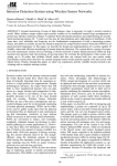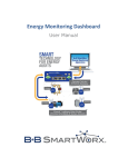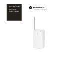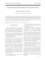
1
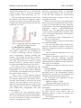
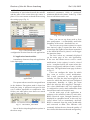
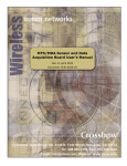
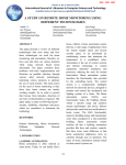
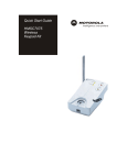
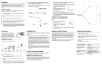
Review of the Air Force Academy No 2 (24) 2013 BROWSER-BASED HOME MONITOR USING ZIGBEE SENSORS Marian ALEXANDRU, Vlad URSU “Transilvania” University of Brasov, Romania Abstract: A study of how to implement a web application used to remote monitor parameters read by wireless sensors placed in the rooms of a home is described in this paper. The main goal of our work was the migration of certain features of the MoteView proprietary software package (provided by the manufacturer) in this web application and adding new features or fixing some existing drawbacks. The system created by us displays on a secured web page home specific environmental parameters, and indicates the status of the set values also, sending e-mail alert to the user when various events occur. Keywords: ZigBee,web browser, database, mesh network, MoteView 1. INTRODUCTION Many applications have been developed over the years, which aim to transform homes and office spaces into comfortable and safe places. This requires sensors and equipment to gather data read by them (temperature, humidity, pressure, light, etc.). However, these data must be sent remote in some cases, to make decisions and act in the opposite direction, to change the (environmental) parameters. Browser-based term in the title is the first clue to the fact that we chose to monitor these parameters via a web application. The major advantage of web applications in comparison with a classical application is the facile management of clients. In the case of applications for which there are many clients, there is no need for each client to install software packages that can sometimes reach large dimensions. Another considerable advantage of web applications is the software / hardware platform dependence removing. These can be accessed using almost any existing browser from workstations which can run under Linux, Windows or Mac. As data acquisition from sensors evolved, specific standards appeared. One of them, which we use in this paper, is the one designated to low range wireless sensor networks (IEEE 802.15.4). LR-WPAN (Low Range - Wireless Personal Area Network) is used for information transmission over relatively short distances and transfer rates up to 250 kbps. The IEEE 802.15.4 standard, for these kinds of networks, defines the physical layer and medium access sub-layer for wireless connections having lowspeed data transfer between devices with low power consumption. The main objectives of LR-WPAN are ease of installation, the secure transfer of data, and a reasonable battery life, operating on short ranges, at low price while keeping a simple and flexible protocol. ZigBee, defined for IEEE 802.15.4 is a standard for low power and low-speed wireless networks, designed specifically for remote monitoring and control applications. While IEEE 802.15.4 can only support 255 nodes in the physical network, The ZigBee network addresses support on 64-bit extended this number to 65,000 nodes. A ZigBee device can be Full Function or Reduced Function. A ZigBee sensor network must contain at least one Full Function device that will act as network coordinator; we used only Full Function equipment. 17 Browser-based home monitor using zigbee sensors 2. IMPLEMENTATION OF THE MONITORING SYSTEM 2.1 Equipment used. Mesh topology involves a special network of ad-hoc type (in our case), highly scalable, which is selfforming and self-regenerating, reliability and lifetime being maximum. For these reasons we have chosen for our application such topology, using six nodes (MICAz motes) and a gateway The radio processor (MICAz Processor Radio - MPR2400) uses a transceiver (2400 2483.5 MHz) for ZigBee, in accordance with 802.15.4 standard, which it is integrated with a micro-controller ATMEGA128L. Programming these nodes is performed using the MIB520 (Mote Interface Board) interface, with USB port. Fig. 3. Sensors board MTS400/MTS420 Fig. 1. Mesh network built with the Crossbow development kit Our web application picks and interprets the measurements performed by the sensor network. The WSN Professional development kit used by us (manufactured by Crossbow Technology, Inc.) includes six preprogrammed MICAz mote sensor, plus a gateway (MIB520 with extension), a data acquisition board (MDA300) and a programming board through USB (MIB520). A MICAz mote and its block diagram are presented in the Fig. 2. Each MICAz sensor includes a MTS400/420 acquisition board on which various sensors (temperature, humidity, pressure, light, acceleration on OX and OY axis, or even a GPS module) are integrated (Fig. 3). Fig. 2. MICAz and its block diagram 18 Features offered by MTS420 boards allow a wide range of applications ranging from a simple weather station to a full network of environmental monitoring nodes, and can be part of more complex systems (HVAC - Heating Ventilating and Air Conditioning). MDA300 is a versatile acquisition board that is suitable for applications monitoring ambient parameters. This board has two integrated sensors (humidity and temperature) and allows connection of additional sensors on the digital and analogue channels. In order to detect possible break-ins in the home, a magnetic contact door / window was connected to the MDA300 acquisition board, only for demonstration purposes. Instead, other types of sensors may be connected, depending on the application. The magnetic contact was connected to A2 analog channel as shown in the Fig. 5. Fig. 4. MDA300 acquisition board Review of the Air Force Academy As long as the contact is closed, the voltage measured on channel A2 is 0 V, and when the contact is open (door is open) the measured voltage will have values in the range 1.4-1.7V. The web application reads these values from the database, and when the magnetic contact opening is detected in the specified timeframe, it triggers the intrusion alert, and sends this alert to the user via e-mail. Fig. 5. Connecting magnetic contact to the MDA300 A2 analog channel 2.2 The MoteView Solution The Crossbow kit contains both the hardware and software required for the installation of a network monitoring ambient parameters such as temperature, lighting, humidity and pressure. The solution provided by Crossbow can be divided into three levels: Sensors, Server and Client. The first level consists of a mesh network (6 nodes + gateway) and is designed to collect data and provide them to the server. The Server level is represented by the Xserve application. This is a daemon that runs continuously on a PC station and is designed for buffering and translation data provided by the wireless sensor network. Xserve serves as main gateway between the wireless sensor network and visualization and analysis applications. Essentially, Xserve provides data routing to and from the mesh network, and also superior level services of analysis, transformation and processing of such data. Superior level services are customizable using XML-based configuration files and loaded plug-ins. To achieve our web application Xserve method was used for insertion into the database. The server can introduce into the results table a new row for each set of values received from a sensor or can update rows, also. No 2 (24) 2013 The Client level is represented by the MoteView application which is responsible for the graphical interface. This level provides to the user data collected by sensors using common units such as degrees Celsius, Lux, percentages and Volt. Moteview can be used to view data acquired from a single type of acquisition board at a time. If there are several MICAz motes within the mesh network, each of them including different acquisition boards (MTS400/MDA300/ MTS420, etc.), the application cannot show to the user data acquired from all boards. This is one of the major drawbacks of the proposed Crossbow solution. The following are other disadvantages of the Moteview application: - Requires relatively large space on the hard drive (about 200 MB); - If it is desired to monitor the wireless sensor network from multiple computer stations, the MoteView application needs to be installed on each of these; - The port that the application uses is an insecure port (9001); - Platform dependent. MoteView is only compatible with the following operating systems: Microsoft Windows XP Home Edition, Microsoft Windows XP Professional, Windows 2000 (only ServicePack4); - Minimum resolution on which can run is 800x600. 2.3 Our solution Our goal was to develop a web application that takes some of the functionalities offered by MoteView, provides new functionalities and eliminates the disadvantages listed above. The developed web application has the following advantages: - Small size (approx. 2 MB); - Minimum requirements (no special computing power needed to run the web application); - Platform independence: instead MoteView, the client will be a web browser. Thus, an unlimited number of users can monitor the sensors network; - The web application can run on any operating system; 19 Browser-based home monitor using zigbee sensors - Instead of port 9001, port 80 is used; - Configurable warning function were included; - The web application sends by e-mail notifications to the user; - Security features were implemented (eg. forced entry alert). 2.4 Storing and accessing data XServe inserts all the data acquired from the sensors to a PostgreSQL database. PostgreSQL is a relational database and is available for free under Open Source license. Data from the sensors are placed in the MTS400_results table; each data acquisition board has a corresponding table in the database. The web application accesses this table through a DAO (Data Access Object); a second DAO is used for the intrusion alerts table. DAO methods are useful for opening the connection, executing the query and closing the connection to the database. A critical point in the development of the home monitoring web application was the knowledge of the database structure provided by Crossbow. Detailing the structure of the database is not subject of this paper, in which only new items added will be presented. One of the top features of the developed web application is represented by the configurable alerts. The user can set different alert conditions using the acquired values from the sensors. For example, the application can be configured to trigger an alert if the temperature in one of the rooms in which it was placed a sensor falls below a certain threshold. To implement this mechanism, storing additional data in the database is imperative. Database used by Xserve cannot be altered. Any changes can make the select or insert operations performed by the server to return errors. In order not to compromise the integrity of the system, we created a supplementary database (Alert), which stores the data used by the alerting function. The new database contains four tables: Alert, Alert_log, Room and Sensor_user. 20 Fig. 6. The Alert database, including 4 tables Fig. 7. The Alert table The significations of the parameters are: Unit: is the sensor identifier that triggers the alert; Lower and Upper: margins where alerts are triggered; Name: the alert title; Active: Boolean variable (true/false) indicating whether the alert is active or not; Email_notification: flag that determines if the alert will be sent to the user by e-mail. Fig. 8. The Alert_log table In Fig. 8 the table that stores the alerts displayed on the main page of the web application is presented. The alert_time and alert_end_time fields are used by the application to assess the alerts status. An alert where only alert_time field is set appears as active on the web interface. Review of the Air Force Academy The Room table is used only to create a relationship of association between the nodeID and the name of the room where the sensor is placed. User can rename each nodeID accessing the settings page (Fig. 9). No 2 (24) 2013 The user can create an alert condition using monitored parameters, fields of maximum, minimum and the alert name. In the Fig. 12 the form to add alerts can be seen. Fig. 12. Form to add alerts Fig. 9. The Room table and the configuration section from the web application 2.5 Application functionalities A mandatory element of any web application is the login page. Fig. 10. The Login page for the web application User passwords are stored in encrypted form in the database. Encryption mode is based on hash plus jump. A password encrypted in this way is almost impossible to compromise. The Sensor_user table where user data were stored can be seen in the Fig. 11. Fig. 11. The Sensor_user table One of the developed application options is the alerts setup. Thus, you can set up alerts such as frost alert (temperature < set threshold), mold alert (humidity of the room > threshold set), etc. The user can set up alerts so that in a certain time interval, when is opened the door of the room where the ZigBee sensor that was attached to the MDA300 board is placed, it will trigger the intrusion alarm. The last 8 alerts are constantly displayed on the main page of the web application. If the user has chosen not to receive e-mail notifications, in the registry it can be viewed active / completed alerts, the rooms where the alerts were triggered, and time of enter / exit the alert state. The application home page is shown in Fig. 13. Users can configure the alerts for which they want to receive e-mail notifications. The e-mail generated by the application includes: the time the alert was triggered; the sensor for which the alert has been configured (temperature, humidity or light); the room where the alert has been triggered. Through a Java class (MailSender) the web application is configured to send e-mail notifications both into alertness and exit from this state. On the main page of the application, in addition to the measured values of each node, RSSI (Received Signal Strength Intensity) is displayed in a graphical mode. In this way, any sensor failure can be immediately observed. RSSI is extracted from the node_health table and converted to dBm. This indicator will constantly inform the user about the quality of the wireless link between the node and gateway. 21 Browser-based home monitor using zigbee sensors In Fig. 13, lines marked with green color symbolize the normal parameters, the ones marked with pink indicate the values that are out of the set ranges, and the red lines indicate that there was an intrusion alarm. Considering the application description above, we believe that our work has immediate practical applications and offers a wide range of benefits. The future work will consist of: - Changing the application so that it will be transformed from a house monitor into an automation application, using ZigBee sensors + actuators; - Installing the application on a dedicated server and configuring the remote access to it; - Building a complex domotic system around our application. REFERENCES Fig. 13. The web monitoring application homepage 3. CONCLUSIONS & FUTURE WORK This paper presents the steps that we followed and equipment used to set up a remote house monitoring system. Due to the fact that it is very scalable, this system can be extended to a wide range of applications. Information about the developed application source code can be obtained from the authors, who considered that it is not subject of this paper. 22 1. Bates, B., Sierra, K. (2003). Head First 1. Bates, B., Sierra, K. (2003). Head First Java, O’Reilly Media. 2. 2. Lin, C., Young, S., Kuo, T. (2007). A remote data access architecture for homemonitoring health-care applications. Source. [online]. Available: http://www. orcatech.org/papers/home_monitoring/07_ Lin_remote_data_access.pdf [2012 june 12]. 3. 3. *** MDA300 Data Sheet. Source. [online]. Available: http://www. investigacion.frc.utn.edu.ar/sensores/ Equipamiento/Wireless/MDA300CA_ Datasheet.pdf [2012 june 12]. 4. 4. *** XServe User Manual. Source. [online]. Available: http://www.pdfio. com/k-436819.html [2012 june 12]. 5. 5. *** (2009). ZigBee Wireless Sensors: Applications for Health, Wellness and Fitness. Source. [online]. Available: https:// docs.zigbee.org/zigbee-docs/dcn/09-4962. pdf [2012 june 19].