1
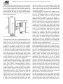
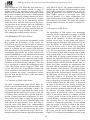
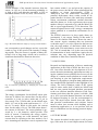
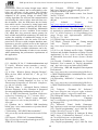
EJSE Special Issue: Wireless Sensor Networks and Practical Applications (2010)
Intrusion Detection System using Wireless Sensor Networks
Absar-ul-Hasan1, Ghalib A. Shah2 & Ather Ali3,
1,3
2
National University of Science and Technology, Islamabad, Pakistan
Center for Advanced Research in Engineering, Islamabad Pakistan
ABSTRACT: Ground monitoring of areas of high strategic value is necessary in today’s security sensitive
world. Often, military setups require tight security cordons to be established around large encampments to
protect any intruder, malicious attacker or saboteur from entering the premises and compromising its security.
Such monitoring requires 24 / 7 watch over the area for long durations and a high degree of stealthiest. At the
same time, cost, reliability and longevity are the fundamental requirements of such a monitoring system.
Hence, the ability to monitor an area for intrusion detection by using Wireless Sensor Networks (WSNs) is of
great practical importance. In this paper, we describe the design and implementation of a system capable of
reliable, robust and efficient monitoring for human intrusion detection. The system allows a group of cooperative but autonomous sensory devices forming a wireless network to detect human presence within the deployment area and also track the positions of moving target. We evaluate the performance of the system consisting up to 30 nodes that includes MicaZ motes and also our custom built low cost sensor nodes.
Performance results show that how the custom designed sensor nodes perform equally well and coexist with
MicaZ motes. Finally, through this paper, we share our experiences and the valuable lessons learned in developing such a complete running system.
1
1. INTRODUCTION
Security is today one of the primary concerns around
the world. Recent trends have shown that surveillance of tactically important areas for suspicious activities is a high priority for organizations. Despite
technological advances, the major threat that still
lurks is from unauthorized humans who can gain
access to a target location and compromise its integrity. This results in surveillance of key areas for
possible intrusion to be one of the most desired
goals for security. Wireless Sensor Networks
(WSNs) are one of the most contemporary and successful technique used for environmental monitoring
of certain physical parameters. WSNs can be effectively used to gather useful data from the physical
environment they are deployed in and communicating that information wirelessly to base stations
which can process it and extract useful information.
WSNs are envisioned to reduce, and eventually,
completely eliminate human involvement in information gathering in certain applications [1]. However, they have their own limitations, the most important of which is the amount of energy available to a
sensor node. With slow progress in energy scavenging, the current solutions need to be very energyefficient; using the minimum amount of energy
while having the maximum useful throughput. Other
major challenges faced by WSNs are tamper resistance,
unobtrusiveness and real-time constraints
Despite these limitations, WSNs do have the advantage of deploying sensors in hostile environments
autonomously. This fulfills a very important need for
any real time monitoring, especially in remote scenarios. These advantages and disadvantages of
WSNs compel development of a system which can
be deployed and tested in the real-time environment.
Evaluations done through simulations tend to make
simplified assumptions which fail to hold well in
practice rendering the simulated systems incomplete.
Simulation does, however, give an in-sight on the
operation of such systems under ideal conditions,
which can be a scale to measure the results achieved
in real world scenarios [2].
In this paper, we describe our effort in designing and
implementing a system on a network of up to 30
sensor nodes, with at least half of them being MicaZ
motes and the rest our own designed sensor nodes.
The primary goal is to build a system, which is able
to reliably and stealthily detect human presence, and
track the movement pattern of the human within the
sensor network with minimum cost, size and energy
consumption. The core of the system is use of the
Passive Infrared (PIR) sensors, which are interfaced
to the MicaZ motes and custom designed sensor
nodes. PIR sensor responds to the infrared radiation
of the human body and is quite reliable in determining human presence within its sensing range [3], [4].
The remainder of the paper is organized as follows.
Section II describes the application scenario i.e. application requirements for which this system is implemented. Section III describes the hardware and
1
This work is supported by TWAS Italy under the grant
number 09-068-C.
90
EJSE Special Issue: Wireless Sensor Networks and Practical Applications (2010)
software components and the system setup. Section
IV discusses the implementation details of the system. Section V provides system evaluation results
and lessons learned from our experience. Conclusion
is presented in section VI.
2. APPLICATION REQUIREMENTS
The design of our system is motivated by the requirements of a perimetric monitoring application.
The general objective of such an application is to
monitor the perimeter, in most cases a boundary wall
for any human presence over the wall or within
some distance of it. The base station, where all the
information is sent, needs to have a map of the entire
security perimeter and human detection at any segment of the wall must be reported to the base station
with acceptable latency. Some applications requirements which must be satisfied to make our system
useful in practice are following. First, continuous
monitoring requires the sensor devices to be active
all the time. Therefore, energy conservation schemes
are required so that lifetime of sensor devices can be
extended for uninterrupted active sensing. Second,
the perimeter must be entirely covered without any
unattended spaces in between any two nodes. This
requires effective and acute positioning and orientation of the sensor devices. Third, it is crucial for the
sensor nodes to have a very low possibility of being
detected by the intruder which can then, possibly,
find a way to bypass detection. Small physical size
of sensor nodes along with zero RF communication
is desired in absence of significant events. Fourth,
effective detection of human presence along with
low reporting latency is also required so that active
countermeasures can be deployed against the threat
well in time. Fifth, the sensor nodes need to communicate with each other in a line topology since wall
coverage is done by placing sensor nodes in a semistraight or straight line. Thus, the routing must be
done in such a way to ensure that radio links are
maintained even if any node goes down.
tures an Atmel ATmega128L low powered microcontroller with 128K bytes of program flash memory, 512 Kbytes measurement (serial) flash and 4K
bytes configuration EEPROM. The device also has a
250 kbps, 2.4 GHz, IEEE 802.15.4 standard compliant, MPR2400 radio. The MicaZ motes provide
low power operation (8 mA current draw in active
mode and lesser than 15 μA draw while in sleep) and
a radio range of up to 100 m. It makes it an ideal
platform for large-scale, long-term deployment. The
MicaZ mote also has a 51-pin expansion connector
which supports analog inputs, Digital I/O, I2C, SPI
and UART interfaces. These interfaces make it easy
to connect to a wide variety of external peripherals.
The 51-pin expansion connector is used to interface
the PIR sensor with the MicaZ mote. The MicaZ is
powered by two AA batteries [5].
The cost of one MicaZ mote is approximately US
$130 (incl. shipment cost). The physical parameters
of MicaZ motes help to achieve the stealthiness required by the application. A MicaZ mote is also used
as a gateway to aggregate the sensor network data
onto a PC where base station monitoring application
visually displays the data on a user-friendly GUI.
For the gateway node, a MicaZ mote is attached to a
MIB520 interfacing board via its 51-pin expansion
connector which provides USB connectivity to MicaZ motes for communication and in-system programming. The MIB520CB offers two separate
ports: one dedicated to in-system Mote programming and a second for data communication over
USB. The MIB520CB has an on-board processor
that programs mote processor radio board. USB bus
power eliminates the need for an external power
source [6].
3. SYSTEM COMPONENTS AND SETUP
3.1 Hardware
The hardware platform used for the outdoor test-bed
consists of two sensor node types. Firstly, the industry standard MicaZ motes are used and secondly, in
order to reduce the cost of each sensor node, we
have designed our own custom sensor node using
discrete components (micro-controller, voltage regulating switches, ZigBee transceivers etc.).
1) MicaZ Motes: MicaZ is a crossbow Inc.’s flagship commercial mote designed for applications to
run in low power wireless sensor networks. It fea-
Fig. 1.Block diagram of custom designed sensor node.
2) Custom Designed Sensor Node: A new sensor
network hardware platform is designed in order to
reduce the cost up to US 50$ per node, which is half
the cost of MicaZ platform. For our application
which requires dense sensor node deployments to
increase system reliability and effectiveness, sensory
devices should be as much cost effective as possible
while maintaining efficient detection and operation.
For RF communications, we have used the Telegesis
EJSE Special Issue: Wireless Sensor Networks and Practical Applications (2010)
ETRX2-PA module, which is a power amplified
2.4GHz ISM band transceiver based on the Ember
EM250 single chip ZigBeeR/ IEEE802.15.4 solution. This transceiver enables us to communicate
with the base station PC for reporting the sensor’s
detection data. The module is based on AT style
command line interface that allows us to communicate with transceiver on the custom sensor node
through RS-232 serial interface [8]. It has small
form factor measuring at 37.5 x 20.5 x 3.2 mm and
supports data rate up to 250 kbps with 16 channels
(802.15.4 Channel 11 to 26). Also, the device supports four different power modes for extended battery life which we have extensively used. The device
has very flexible input voltage requirements and can
operate between 2.1- 3.6 V DC input, with current
draw as low as 1A in deep sleep mode. This makes it
an ideal choice for low powered energy efficient
node design [9].
3) Sensor for Human Detection: In outdoor conditions, the sensor network needs to detect the presence of stationary as well as walking or running human beings. Other properties of the sensor for such a
scenario are lower power operations with lesser
processing power requirements. The size and cost of
the sensor should be reasonable so as to make the total size and cost per node under check for maximum
cost and size effectiveness. At the same time, the
sensor should be powerful enough to detect objects
at long range while being reliable (they should not
give false positive or negative readings).Considering
the design requirements, different sensors could
have been used for human detection and tracking.
The sensors which came under our consideration
were accelerometer (seismic), ultrasound (ultrasonic) and infrared (thermal). Based on the analysis reported in Table I, ultrasound sensor is excluded
since low-power property is required. Comparing
the accelerometer and the infrared sensor, the infrared sensor has better detection properties for movement.
of movement. We have used Hygrosens low power
PIR motion sensor, which operates with pyroelectric sensors and shows maximum sensitivity under the effect of heat radiation from living bodies
[10]. At 37 degree Celsius body temperature, the
spectral sensitivity lies between 7 and 14 μA. The
PIR sensor is segmented form inside i.e. two or more
individual elements are interconnected within the
unit so that they mutually compensate with each
other. With this the self-temperature of the sensor is
compensated. A MOSFET is integrated in the sensor
as an impedance converter because the pyroelements can only be driven by high ohmic value.
As depicted in Figure 2, a change in output voltage
occurs only when the part segments of sensors experience different levels of infrared radiation.
A person passing the sensor will first activate one
element and then the other, which gives a positive or
negative difference between the elements depending
on which element is activated first. As soon as the
signal level, indicating the difference between the
elements, exceeds a certain limit, a digital switching
signal is generated. This is further processed by the
micro-controller that handles it as an interrupt. Figure 3 shows the changes in the voltage reading of the
sensor as the person passes through the detection
area of the sensor. The pyro elements of the PIR
sensor are covered by Fresnel lens [11], which enhances the capability of the sensor by dividing the
space in front of the sensor element into segments.
The sensor has operating voltage of 3.5 V DC with
80 μA current input. This makes the PIR sensor ideal
for battery powered operations. The sensing range of
PIR sensor is 12 m with an opening angle of 120 degree. Also, the sensor can operate at temperatures
upto 70 degree Celsius [10]. Since the PIR sensor is
made as a separate unit, it needs to interface to the
51-pin expansion connector of MicaZ motes and the
pins of micro-controller.
Fig. 3. Analog output signal of PIR sensor [10].
Fig. 2. Illustration of movement detection with PIR sensor
[11].
Thus the sensor used in this project is a thermal sensor, more precisely a passive infrared sensor (PIR).
Another advantage is that the analog output signal of
a PIR sensor can give an indication of the direction
3.2 Software
1) TinyOS: The software running on the MicaZ
sensor nodes is written in nesC [12] and run on TinyOS [13], an event driven operating system developed for wireless embedded sensor platforms. TinyOS is written in nesC, a programming language
92
EJSE Special Issue: Wireless Sensor Networks and Practical Applications (2010)
with a C-like syntax for programming network embedded systems. nesC applications consist of one or
more components linked together to form an executable.A component provides and uses interfaces. Interfaces declare a set of functions called commands
that the provider of the interface must implement.
Another set of functions called events that the user
of the interface must implement. nesC has two types
of components: modules and configurations.
Modules implement one or more interfaces. Confi
gurations are used to assemble other components together, connecting interfaces to their implementation. This is called wiring [14]. The TinyOS tools
are available for Linux and Microsoft Windows (under Cygwin) and contain various tools: nesC compiler, AVR compiler and utilities (for Atmel microcontrollers) etc. and a sensor network simulator,
TOSSIM.All our simulations for nesC based applications are done in TOSSIM [15]. TOSSIM simulates the entire TinyOS network stack at the bit level, allowing experimentation with low-level
protocols in addition to top-level application systems. It works
by replacing components with simulation implementations. When it runs, it pulls events of the event
queue which is sorted by time and executes them.
Depending on the level of simulation, simulation
events can represent hardware interrupts or highlevel system events (such as packet reception).
Additionally, tasks are simulation events, so that
posting a task causes it to run a short time in the future [16].
2) Custom Node Implementation: Application
program for custom node is written in C programming language and compiled and burned on the micro-controller using the Microchip MPLab IDE [17]
and C18 compiler [18]. C was used as a programming language to develop detection application because it provides time and management efficiency
with the micro-controller. The same application
code written in assembly would be much longer,
with subsequent changes and code maintenance being difficult. Application development was done using the tools available in the MPLAB Integrated Development Environment (IDE) which is a free
toolset for embedded application development with
PIC micro-controller. The MPLAB editor and debugger tool are used to write the C code for our application and then compiled using the C18 compiler.
For controlling the RF transceiver, we used the Telegesis Terminal PC Software/HyperTerminal which
accesses the command line of the ETRX2 module.
This is a utility designed to manage a ZigBee wireless network consisting of Telegesis ETRX2 devices
using the Telegesis AT command set. Telegesis
Terminal enables connection to ETRX2 wireless
meshing modules, sending commands to it and
viewing the responses received from remote ETRX2
devices [19].
3) Base Station Monitoring: The monitoring application at the base station is developed using the
C# programming language with Microsoft Visual
Studio 2008. C# is a modern, general purpose object
oriented programming language suitable for development of software components in distributed environments. It is also suitable for writing applications
for embedded systems and uses strong type checking, array bounds checking and other features to
bring software robustness, durability and productivity [20].
Fig. 4. MicaZ sensor platform setup.
IV. SYSTEM IMPLEMENTATION
The system is implemented using the MicaZ and
custom designed nodes cooperatively to monitor the
human presence through a base station application.
The MicaZ based sensor devices communicate with
each other and traverse their data to the base station
whereas the custom designed sensor nodes also
communicate with the base station which has the gateway node for both the MicaZ and custom sensor
nodes. The entire setup is shown in Figure 4.
Fig. 5. Application architecture. It uses a timer to act, PIR sensor to collect data and CTP routing layer to deliver data to sink.
The core MicaZ sensor node application is the Detection-Interrupt module, a multiple mode event generator for human detection and node availability.
The sensing application relies on various services
and subsystems that facilitate network management
and interaction. Figure 5 [22] describes the software
services on the MicaZ sensor platform.
The DetectionInterrupt module relies on the Collection Tree Protocol (CTP) [23] which enables reliable, robust and efficient data collection. It works by
building one or more collection trees, each of which
is rooted at a base station When a node has data
EJSE Special Issue: Wireless Sensor Networks and Practical Applications (2010)
Sensor
Infrared
Ultrasound
Low power
Yes
No
Processing
Low
High
Reliability
Medium
High
Size & Cost
Low
High
Accelerometer
Yes
Low
Low
Low
TABLE I PROPERTIES OF DIFFERENT TYPES OF SENSING MODULES FOR HUMAN DETECTION
which needs to be collected, it sends the data up the
tree, and forwards collected data that other nodes
send to it. Each node in our system can perform four
different roles in collection: producer, snooper, innetwork processor, and consumer. Depending on
their role, the odes use different interfaces to interact
with the collection component, which in our case is
the base station node. The configurations of the
routing stack of CTP are shown in Figure 6 [24].
lo packet by the base station node in order to confirm node availability. Type 3 packet is sent through
the radio link when detection is made and the interrupt variable is true that contains the interrupt value,
node id and packet identifier as its payload. All incoming radio packets from MicaZ motes are received by the gateway node which simply forwards
the message received on its radio link to the serial
communication port of the PC from where the monitoring application takes over.
a) MicaZ sensor mote. (b) Custom designed node
Fig. 6. Some CTP routing stack configurations [23].
Fig. 7. PIR sensor integrated with two different platforms.
The PIR sensor is interfaced with the 51-pin expansion connector of the MicaZ mote using the external
interrupt pins of the MicaZ mote as shown in Figure
7(a). Whenever the sensor generates a DC interrupt,
it is recognized and the DetectionEvent module triggers the RadioMessage event which then forwards
the interrupt along with the node id in a radio packet
towards the root, which is the base station node. In
order to distinguish the data packets, we have used
three packet types. Type 1 packet is sent only once
when the entire network is booted that contains node
id from which the packet is being generated and also
the node id’s of all the immediate neighbors of the
node along with the gateway identifier which is true
if the node is in direct radio range of the base station. This is done to ensure at network startup time
that all nodes correctly booted and have full information about their neighboring nodes and can multihop successfully to send their data to the root. Type
2 packet is sent after a period of every 2.5 sec that
contains the node id and a string identifier of the
packet type as he payload and is recognized as a hel
The custom nodes also work in the same way, albeit
different components are used to perform the same
tasks. The PIR sensor integrated with the custom
node is shown in Figure 7(b). To process the information provided by the sensor, PIC18F452 microcontroller is used. It has bi-directional ports which
can be declared as inputs or outputs according to
their purpose. PORT B is an 8-bit wide, bidirectional port. The corresponding data direction
register is TRISB. Setting a TRISB bit to 1, it makes
the corresponding PORT B pin an input. Clearing a
TRISB to 0 makes the corresponding PORT B pin
an output (i.e. put the contents of the output latch on
the selected pin). Whenever the sensor detects an intruder, RB0 which is configured to INT0 will give a
digital interrupt to the micro-controller. It is a negative edge triggered interrupt and when this occurs,
the micro-controller comes out of the sleep mode.
Once awake internal interrupts are called, it converts
analog data of the sensor at AN0 pin to digital data
which is then compared to a pre-defined threshold
value for deciding whether it’s a human or a small
94
EJSE Special Issue: Wireless Sensor Networks and Practical Applications (2010)
rodent or any other animal. Due to this, weak signals
are discarded and once the detection comes out to be
in the desired range of values, the microcontroller
gives a unicast command to ETRX2 RF module via
a data string through its TX (pin 25) which is connected with the RX (pin 28) of the ETRX2 module.
After that the microcontroller returns to sleep mode
till next detection occurs.
Fig. 8. PCB connection diagram.
To minimize overall power consumption of the network, the custom sensor platform consists of two
kind of devices; the first kind are declared as mobile
end devices while others are fully functional devices
to function as routers. Each router has multiple
(usually 8-10) mobile end devices as its children.
PCB connection diagram of the router node is shown
in Figure 8.All network related tasks are performed
by the routers and the mobile end devices are asleep
and wake up after an intrusion is detected only to
notify its parent router. After notifying, they go back
to sleep again. There is no other task of a mobile end
device, therefore we do not need micro-controllers
on them, thereby reducing power consumption.
A mobile end device only has a ETRX2 standard
module which is interfaced with a sensor. When the
sensor detects it informs the ETRX2 RF module at
I/O11 [Ref ETRX2 Command Manual] which is
physically its pin 31. It is a falling edge therefore bit
6 of S10 register is set to correctly configure
ETRX2. When such external interrupt occurs, an internal interrupt IRQ3 is generated for which the
functionality register is S26. This register holds the
code of specific functionality which we need the
ETRX2 module to perform when an external interrupt at I/O11 occurs. We set it to 8110 that sends the
reading of the I/O, the two analogue ports and Vcc
as well as an 8-bit transmission counter to the sink.
If no sink is known, then the node searches for a
sink instead. The router is responsible for delivering
data of end devices to sink by collaborating with
other routers present in the network managing the
whole network while end devices are dedicated only
to intrusion detection.
A standard module is declared as a mobile end device by changing the contents of S-register 0A, bits
F-E to 11. By default it is 00 i.e. a router. The reason
for declaring a mobile end device is that it cannot
move around the network, e.g. if its location is
changed in the network, it dynamically changes its
parent to a nearby router. Furthermore a mobile end
device is kept in a low power mode to consume less
battery. This is done by changing the S-register 39
contents to 0002; basically this enables the module
to fall asleep. If no polling and other timed actions
are performed the power consumption can be as little as 1.5 μA in this mode. However due to polling
we expect this value to be little more. The data is
passed on to network sink which is serially connected to the computer. The sink is essentially the
same module but it can connect serially to the computer. A node can be declared as sink by setting bit 4
of S-register 10. Hence all data coming from the
network can then be manipulated in any desired
manner once it is at the serial port. fig 9 displays the
end device picture and MicaZ sensor node. Note the
same PIR sensor on both platforms.
The base station performs two tasks; first, it receives
packet from MicaZ through other nodes connected
to the MIB520 interfacing board. Secondly, it transfers received packets from network to serial USB
port. The monitoring application parses the received
packets over serial port and filters out relevant information such as packet type, node ID, interrupt variable’s value. According to the packet type detected, specific action is taken by the monitoring
application. For packet type 1 in case of MicaZ
based network, the application displays a popup alert
with the information that mote ID x has joined the
network. The user at the monitoring PC has to map
the node to the correct location on the screen which
displays the map of the area under surveillance. The
node icon is placed at a position in the GUI depicting the actual physical location of the sensor node.
In case of type 2, blue wireless bubble is drawn on
mote ID x which shows that the mote is alive. For
packet type 3, same bubble is drawn but in red color
that depicts the event detection at node x.
In order to track the intruder, the proposed algorithm
uses the information received from both the custom
node platform and the MicaZ platform. When a human is detected by either of the platforms, it is reported to the base station and visual notification is
EJSE Special Issue: Wireless Sensor Networks and Practical Applications (2010)
made through the GUI. When the next detection is
made (assuming the intruder moved in range of
another sensor), the detection at new node ID is
made and we compare the current detection ID from
the previous detection ID to create a tracking arrow
which gives a relatively reliable direction of movement of intruder within the sensor network. A single
intruder, in this way can be continuously tracked
within the sensor network with respect to the physical placement of the network. Since the application
requirement is to place the sensor nodes over the
wall in a line, intruder can change positions from being in one sensor’s range and then in another’s, thereby making this tracking strategy effective.
5. PERFORMANCE EVALUATION
In this section, we present the experimental results
that evaluate the performance of the system described in the previous sections. Results are obtained
by deploying MicaZ and custom designed sensor
nodes in a straight line on a grassy field depicting
their deployment over the boundary wall. For energy
consumption experiments, the system needed to be
deployed unattended for long durations which could
not be done due to security issues, so energy consumption experiments were conducted with a smaller number of nodes in controlled environments. Experiments are divided into three categories. The first
set of experiments evaluates the transmission range
of the MicaZ radio and the Telegesis ETRX2 transceiver. The second set of experiments evaluates the
sensor capabilities and finally the last set of experiments evaluates the energy consumption calculations for both the MicaZ sensor nodes and custom
designed sensor nodes.
5.1 Evaluation of Sensor Node Radios
The radio communication of the MicaZ motes depends on several factors such as antenna length, elevation from the ground, positioning of motes. The
conclusions drawn in experiments are based on the
assumption that the antenna size is same for all MicaZ motes, same elevation above ground with similar line of sight. Under these assumptions, we have
observed the radio range of single hop packet transmission i.e. two MicaZ motes communicating with
each other to be approximately 70 m. This range is
achieved when both nodes were communicating
with the default power levels defined for their radios
in TinyOS. We believe that increasing the power
level for the radio, transmission range can be enhanced to much closer than the theoretical maximum
value which is 100 m. The custom designed sensor
platform has the Telegesis ETRX2 transceiver which
uses ZigBee protocol to communicate. It also depends on almost the same factors as MicaZ motes
since ZigBee protocol is developed over IEEE
802.15.4 protocol [25]. Same assumptions were
made for the custom sensor platform’s radio and results achieved were similar. The single hop communication distance between two nodes is between 70 80 m.
5.2 Evaluation of PIR Sensor
The capabilities of PIR sensors were thoroughly
tested for effective human detection range of the PIR
sensor. We place a MicaZ sensor node with a PIR
sensor at the elevation 1 m above the ground and
perform several tests. At this height with sensor’s
opening angle of 120 degree with variation of 20 degree, we achieve the maximum detection range of
9.1 m (30 ft) This value is about 24% lesser than
what is described in the data sheet of the PIR sensor
[10]. The next experiment is done with the PIR sensor to evaluate its horizontal coverage range with the
same opening angle. A test subject moves in front of
the PIR sensor at varying vertical distances and we
measure the horizontal distance from the center of
the lens until the first detection is made. The results
obtained comply with the fact that Fresnel lens enhances the sensor capability by segmentation and
detection, and the detection cone gets wider as distance from the center increases. The graph in Figure
9 shows the plot of the results obtained. The trend
shows that as the vertical distance from the center of
the PIR sensor lens increases, the angle of detection
(horizontal distance) of detection also increases.
This is due to the segmentation effect from Fresnel
lens covering the pyro elements of the sensor. As the
vertical distance from the PIR sensor is increased,
the angle of detection increases thereby enabling the
sensor to detect at a wider horizontal distance. The
last experiment performed with the PIR sensor was
the detection ratio and reliability when a moving
target passes in front of the sensor at varying distances. A test subject, moving at a constant speed of
1 feet/sec passed in front of the sensor at varying
vertical distances. Assuming that the total detection
and reporting time of one detection event is 1
second, we evaluate the probability of events missed
while the person is moving in front of the sensor.
The probabilities of detection events are plotted
against the vertical distance of the test subject from
the sensor and the results obtained are plotted in
Figure 10. The detection probability decreases as the
96
EJSE Special Issue: Wireless Sensor Networks and Practical Applications (2010)
vertical distance of the intruder increases from the
sensor. At 1.82 m (6 ft) the detection probability is
as high as 85% and degrades gracefully to 22% at
maximum distance of 9:1 m (30 ft). The results do
Fig. 9. Horizontal detection range by varying vertical distance
not correspond to speed changes and we expect the
results to vary if the speed of the intruder is changing rapidly. Thus, the sensor is capable of binary detection even at long range which can be used as a
significant threshold for intrusion detection.
base station within 1 sec and given the capacity of
the power source, the MicaZ sensor platform has the
capability to report approximately ([2700 *
3600]/26.4) 368; 181 detect-tions. Obviously, in
practical deployment, these results would be degraded because of factors like multi hop communication, environment conditions, random detections
and false alarms etc. In the experiments, the average
number of hops is reported to five and the MicaZ are
able to report approximately 57156 detections. The
custom designed sensor node’s energy consumption
values gathered in a controlled environment are as
follows:
The ETRX2 transceiver in sleep mode draws approximately 2 µA current. During Tx/Rx mode, it
draws 36 mA and the PIR sensor draws the same 1
mA current. Again, assuming that one detection
event takes up to 1 sec to be reported to the base station, the total number of detections which can be
made with 2700 mAh battery source turns out to be
255, 790. It is noted that 1 sec is the worst case time
for transmission of such a small data. Again, the calculations may vary depending upon the physical
condition or other above mentioned factors.
7. CONCLUSION
Fig. 10. Detection probability by changing the vertical distance.
6 ENERGY CONSUMPTION
The energy consumption for the MicaZ sensor platform are as follows: the current draw for the microcontroller is 8 mA in active mode and 15 µA in
sleep mode. The CC2420 radio on the MicaZ mote
draws 19.7 mA in Rx mode and between 11 – 17.4
mA in Tx mode. While in idle mode, the current
draw for the radio is 20 µA. The PIR sensor draws 1
mA current in ON state. The sensor platform is powered by 2 x AA batteries, which provide 2700
mAh of current. Considering the energy requirements for reporting one event detection, the total
current draw in reporting to the base station is 26.4
mA. Assuming one detection event is reported to the
Research and implementation of diverse monitoring
applications in the field of WSNs has been very active. Our efforts describe the development of an intrusion detection monitoring application not only using the standard sensor platform but focuses on the
design of a custom sensor platform at a much lower
cost keeping in view the application requirements.
Moreover, the ability to integrate both platforms into
one standard WSN application is the highlight of our
efforts. The field evaluation results of the system
with 30 sensor nodes, half of which are MicaZ and
half our own custom designed platform correspond
to the cost efficient intrusion detection. Field experiments result show that the system is reliable, with
up to 85% successful human detection rate and can
be deployed keeping in view the environmental issues. The major lesson learned from this effort is
that practical considerations and real-time factors
must be taken into account while building such a
monitoring application, so it can perform well not
only in simulation, but also during practical deployment.
8. FUTURE WORK
The system described in this paper is still a prototype, with room for several improvements for better
EJSE Special Issue: Wireless Sensor Networks and Practical Applications (2010)
performance. There are many design issues which
can be solved to enhance the overall usability, reliability and efficiency of the system. This includes
improving the power consumption and energy consumption of the system, design of robust WSN
routing algorithms for efficient data communication
and securing the entire wireless network from overthe-air attacks. Also, the PIR sensor has its limitations which can be overcome by using better modules, or even by entirely replacing the PIR sensor
with an alternate means of monitoring. Multimedia
sensor platforms are now available in the market
[26] which have low powered camera systems for
more reliable and efficient monitoring. We shall also
explore the usability of multimedia sensors in our
monitoring application. Also, the entire GUI can be
ported on a web server with complete database management to provide a global access to the deployed
network. Node localization issues also need to be
solved and finally a scalable architecture can be developed to allow thousands of nodes in one network
while maintaining the performance requirements of
the application.
REFERENCES
[1] I. Akyildiz, W. Su, Y. Sankarasubramaniam and
E. Cayirci, “Wireless sensor networks: a survey”,
Computer Networks, vol. 38, No. 4, 2002, pp. 393422.
[2] A. Hac. “Wireless Sensor Network Designs”,
Wiley & Sons, ISBN: 0470867361, 1st Ed., pp. 213234, 2003.
[3] S. Ram, J. Sharf, “The People Sensor: A Mobility Aid for the Visually Impaired”, In Proc. of 2nd
International Symposium on Wearable Computers,
pp. 166-167, October 1998.
[4] Keller, Hans J., “Advanced Passive Infrared
Presence Detectors as Key Elements in Integrated
Security and Building Automation Systems”, in
Proc. of IEEE International Carnahan Conference
on Security Technology,pp. 75-77, October 1993.
[5] Crossbow Inc.’s, “MicaZ sensor platform”,
http://courses.ece.ubc.ca/494/files/MICAz
Datasheet.pdf.
[6] Crossbow Inc.’s, “MIB520 USB Interfacing
board”,http://www.astiautomation.ro/produse/Mems
ic/mib520 en.html.
[7] Microchip, “PIC18F452 Microcontroller”,
ww1.microchip.com/downloads/en/devicedoc/39564
c.pdf.
[8] Telegesis, “ETRX2 AT-Command Manual”,
http://www.telegesis.com/downloads/general/TGETRX-R212-Commands.pdf
[9] Telegesis, “ETRX2 Zigbee Module”,
http://www.telegesis.com/downloads/general/TGETRX2PA-PM-003-107.pdf.
[10] Hygrosens, “PIR motion sensor Low Power
Art.No.: 172526”,
http://shop.hygrosens.de/out/media/172526 pir lp
dbe.pdf.
[11]
Infrared
Fresnel
Lens,
http://www.murata.com/catalog/s21e.pdf.
[12] D. Gay, P. Levis, R. von Behren, M. Welsh, E.
Brewer, and D. Culler, “The nesc language: a holistic approach to networked embedded systems”, In
Proc. of ACM Conference on Programming Language Design and Implementation (PLDI’03),
vol.38, pp. 1-11, 2003.
[13] TinyOS, http://www.tinyos.net.
[14] TinyOs, “Tutorial Lesson 1: Getting started
with
TinyOS
and
nesC”,
http://www.tinyos.net/tinyos1.x/doc/tutorial/lesson1.
html.
[15] N. Lee, M. Welshd, and D. Culler, “TOSSIM:
Accurate and Scalable Simulation of Entire TinyOS
Applications”, In Proc. of the 1st ACM Conference
on Embedded Networked Sensor Systems (SenSys
2003).
[16] TinyOS, “TOSSIM: A Simulator for TinyOS
Networks, User’s manual, in TinyOS documentation”, http://docs.tinyos.net/index.php/TOSSIM
[17] Microchip, “MPLAB Integrated Development
Environment”,
http://www.microchip.com/stellent/idcplg?IdcServic
e=SSGETPAGE&nodeId=1406&dDocName=en019
469&part=SW007002
[18] Microchip, “MPLAB C Compiler for PIC18
MCUs”,
http://www.microchip.com/stellent/idcplg?IdcServic
e=SSGETPAGE&nodeId=1406&dDocName=en010
014
[19] Telegesis, “Terminal PC Software:”
http://www.telegesis.com/ telegesis zigbee technology technical support / telegesis terminal.htm
[20] Wikipedia Online Encyclopedia entry on C#
Programming
Language:
http://en.wikipedia.org/wiki/CSharp%28programmi
ng language%29
[21] Microsoft Visual Studio Homepage:
http://msdn.microsoft.com/enus/vstudio/default.aspx
[22] “TinyOS programming”, April 2009 Ed, Cambridge University Press,pp. 8, 2009.
[23] O. Gnawali, R. Fonseca, K. Jamieson, D. Moss
and P. Levis, “CollectionTree Protocol”, in Proc. of
the 7th ACM Conference on Embedded
Networked Sensor Systems (SenSys), 2009.
[24] “TinyOS programming”, April 2009 Ed, Cam98
EJSE Special Issue: Wireless Sensor Networks and Practical Applications (2010)
bridge University Press,pp.49, 2009.
[25] I. Jawhar, N. Mohamed and K. Shuaib, “IEEE
802.115.4: a wireless communication technology for
large-scale ubiquitous computing applications”,
http://ubicomp.algoritmi.uminho.pt/csmu/proc/koub
aa-129.pdf
[26] MEMSIC, “iMote Multimedia WSN Mote information document”,
http://www.memsic.com/support/documentation/wire
less-sensornetworks/category/7-datasheets.html
?download=139%3Aimote2-multimedia.