1
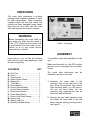
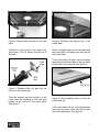
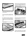
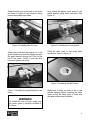
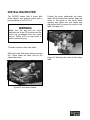
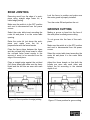
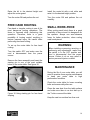
CX200R ROUTER TABLE ATTACHMENT User Manual GENERAL SAFETY INSTRUCTIONS FOR MACHINES Extreme caution should be used when operating all power tools. Know your power tool, be familiar with its operation, read through the user manual and practice safe usage procedures at all times. ALWAYS read and understand the user manual before operating the machine. CONNECT your machine ONLY to the matched and specific power source. ALWAYS wear safety glasses respirators, hearing protection and safety shoes, when operating your machine. DO NOT wear loose clothing or jewelry when operating your machine. A SAFE ENVIRONMENT is important. Keep the area free of dust, dirt and other debris in the immediate vicinity of your machine. BE ALERT! DO NOT use prescription or other drugs that may affect your ability or judgment to safely use your machine. DISCONNECT the power source when changing drill bits, hollow chisels, router bits, shaper heads, blades, knives or making other adjustments or repairs. NEVER leave a tool unattended while it is in operation. NEVER reach over the table when the tool is in operation. ALWAYS keep blades, knives and bits sharpened and properly aligned. ALL OPERATIONS MUST BE performed with the guards in place to ensure safety. ALWAYS use push sticks and feather boards to safely feed your work through the machine and clamp the work-piece (when necessary) to prevent the workpiece from any unexpected movement. ALWAYS make sure that any tools used for adjustments are removed before operating the machine. ALWAYS keep bystanders safely away while the machine is in operation. NEVER attempt to remove jammed cutoff pieces until the saw blade has come to a full stop. 2 UNPACKING The router table attachment is properly packaged and shipped completely in a box for safe transportation. When unpacking, carefully inspect the box and ensure that nothing has been damaged during transit. Open the box and check that the router table and the parts are in good condition. WARNING Before assembling the router table on your table saw, make sure the switch is in the “OFF” position and the power cord is disconnected from the power source. Failure to do so may cause serious personal injury or death. Figure- 1 Inventory ASSEMBLY Inside the box, you will find the following parts with the router table attachment. (Not shown in the picture) CONTENTS A. B. C. D. E. F. G. H. I. J. K. L. M. N. O. QTY Dust Port ......................................... Fence .............................................. Table Inserts ................................... Plastic Router Guard ....................... Starting Pin...................................... T-Slot Bars ...................................... Fence Boards.................................. Router Guard Bracket ..................... Knurled Fence Handles................... Router Guard Knobs ....................... Fence Board Shims......................... Router Hold Down Clamps.............. Support Leg..................................... Support Leg Foot ............................ Mounting Hardware Bag.................. 1 1 2 1 1 2 2 1 2 2 2 4 1 1 1 To install the router table attachment to the saw: Make sure the switch is in the OFF position and the cord is un-plugged from the power source. The router table attachment installed to the saw in two ways: can be 1. Assemble the router table to the extension wing on the right side of the saw. Since the extension wing doesn’t have mounting holes, you will need to drill and tap three holes into the extension wing, matching the ones on the router table attachment. 2. Remove the right hand extension wing and attach the router table to the saw table using the existing mounting holes. See figure-2. 3 Figure-2 Router table mounted to the saw table Figure-4 Attaching the support leg to the router table Thread the foot pad into the support leg. See figure-3. Do not tighten the jam nut at this time. Place a straight-edge on the saw table and the router table, and make sure they are flat with each other. If the router table tilts down, use a masking tape along the bottom edge of the saw table to shim the router table up. See figure-5. Figure-3 Threading the foot pad into the bottom of the support leg Take the support leg and secure it to the router table by threading in onto the stud located at the bottom of the router table. See figure-4. Figure-5 Using masking tape to shim the router table up If the router table tilts up, use masking tape along the top edge of the saw tale to shim the router table down. See figure-6. 4 Place the fence on the table with the studs of the T-slot bars passing through the hole on the fence. Thread the knurled knob on the studs of the T-slot bars and secure the fence as shown in figure-8. Figure-6 Using masking tape to shim the router table down When the router table is installed properly, remove the excessive masking tape using a blade. Now, adjust the foot pad by rotating it so that it sits firmly on the floor and doest not change the router table height alignment. Tighten the jam nut to lock the foot pad in place. Figure-8 Securing the fence to the router table Attach the fence boards to the front left and front right side fence using screws and nuts provided. See figure-9. Slide the T-slot bars into the T-slot as shown in figure-7. Figure-9 Installing the fence boards Figure-7 T-slot bars into the T-slot The fence board shims can be placed between the out-feed fence board and the fence to offset the out-feed fence board. 5 Attach the dust port to the back of the fence as shown in figure-10 and secure it using screws and washers provided. Now, attach the plastic router guard to the guard bracket using knobs provided. See figure-12. Figure-10 Installing the dust port Figure-12 Installing the router guard Attach the screw and the square nut to the guard bracket and slide the square nut with the guard bracket through the T-slot on the top of the fence. Center it with the dust hood and tighten the screw. Place the table insert on the router table opening as shown in figure-13. Figure-13 Installing the table insert Figure-11 Installing the guard bracket to the fence Make sure to clean any dust or dirt on the spindle opening before installing the table insert so that the table insert is flush with the table surface when installed. WARNING To reduce the risk of injury, make sure the router guard is properly installed to the fence. 6 INSTALLING ROUTER The CX200R comes with 4 router hold down clamps and supports router with a base thickness of 1/4" to 2-1/4”. WARNING Position the router underneath the router table, with the hold down clamps. Align the router in the center of the router table opening and tighten the lock knobs and adjustment bolts to secure the router to the table. See figure-15. Make sure the saw and the router switches are in the OFF position and the cords are up-plugged from the power source. Failure to do so may result in serious personal injury. To install a router to the router table: Slide the router hold down clamps through the T-slots under the table and do not tighten the knobs. Figure-15 Securing the router to the router table Figure-14 Hold down clamps 7 OPERATIONS WORK-PIECE INSPECTION The purpose of the Operations Section is to give the operator a basic understanding of how the router table is used for different routing operations. Router is designed to cut wood only, do not cut any kind of metal, stone or glass. WARNING Before starting the router, make sure that you have read and understood the manual and you are familiar with the functions and safety features on this machine. Failure to do so may cause serious personal injury. Before performing any operation, make sure that all the parts are assembled correctly and all the screws, nuts and bolts are tighten properly. Adjust the fence and the bit height according to the depth of cut and to the desired cutting profile. Make sure the router guard is installed properly. Wear safety glasses for your eye protection and make sure that the router table is connected to a proper sized dust collector for adequate dust collection. WARNING The fine dust particles produced by woodworking machines can go inside your lungs and cause serious respiratory problems. Make sure to wear a dust mask and the machine is connected to a proper dust collection system while operation. Before cutting the work-piece, make sure to inspect it for nails, staples, small pieces of stone or metal and any other foreign objects which could come in contact with the bit. If the wood contains any of these objects and it comes in contact with the bit, the object might fly and hit the operator or damage the bit. For safe cutting method always inspect your work-piece carefully before you cut and wear eye protection. Some woods with excessive twisting or wrapping are un-stable while cutting and are dangerous to cut because during operation the work-piece can move unexpectedly which either damage the blade or hurt the operator. If the wood is slightly cupped, make sure the cupped face of the wood is held against the fence. If the bowed side of the workpiece is held against the fence, the workpiece will move while cutting. WARNING The information above is just a guideline for you to understand how to cut a workpiece with slight cupping. If you are not sure and do not have any experience in cutting cupped stock, do not cut it. Failure to follow these instructions might bring personal injuries to the operator or serious damage to the blade Some stock with large knots can damage the bit and wet stock will give a poor result. 8 EDGE JOINTING Removing wood from the edge of a workpiece using straight edge router bit, is called edge jointing. Lock the fence in position and make sure the router guard is properly installed. Turn the router ON and perform the cut. Make sure the switch is in the OFF position and cord is disconnected from the power source. Select the router table insert according the router bit and place it on the router table opening. Raise the router bit just above the workpiece and make sure the bit is perpendicular with the fence boards. Place the fence shims between the fence and the out-feed (left) fence board to offset the out-feed fence board equals to the amount of wood, to be removed from the edge of the work-piece. GROOVE CUTTING Making a groove or bead into the face of the work-piece is called groove cutting. To cut groove into the face of the workpiece: Make sure the switch is in the OFF position and cord is disconnected from the power source. Select the router table insert according the router bit and place it in the router table opening. Place a straight edge against the out-feed (left) fence board and make sure the fence board and the bit flute are even with each other. Adjust the fence boards so that both the boards are even with each other and behind the bit according to the desired depth of cut. Figure-16 Fence position for edge jointing Figure-17 Fence position for grove cutting 9 Raise the bit to the desired height and adjust the router guard. Install the router bit with a rub collar and raise it to the desired height position. Turn the router ON and perform the cut. Turn the router ON and perform the cut carefully. FREE HAND ROUTING Free hand or irregular routing is one of the most dangerous routing operations. The fence is removed while performing this operation. Therefore, there is a great possibility of loosing control, resulting in serious personal injury. Be careful while performing free hand routing. To set up the router table for free hand routing: Turn the switch OFF and make sure the cord is disconnected from the power source. Remove the fence assembly and insert the starting pin in one of the most suitable holes on the router table. See figure-18. SMALL WORK-PIECE When routing small stock there is a great possibility of tear out and it is dangerous for the operator. Always use zero-tolerance fence for better protection, when routing small work-pieces. WARNING When installing or removing, servicing, or performing any adjustments, make sure the switch is in the OFF position and cord is disconnected from the power source. Failure to do so may result in serious personal injuries or death. MAINTENANCE During the life of your router table, you will need to practice some regular maintenance to keep your router table in high performance condition. Check the router table for loose mounting bolts and screws daily after use. Figure-18 Using starting pin for free hand shaping Clean the saw dust from the table surface and make sure there is no dust built up in the T-slots or around the table. Keep the cast iron surface free from rust. 10 ROUTER TABLE PARTS BREAKDOWN & LIST REF# 601 602 603 604 605 606 607 608 DESCRIPTION ROUTER TABLE TABLE INSERT (29mm) 1"D TABLE INSERT (60mm) 2-3/8"D THREADED STUD M8-1.25*40 SUPPORT LEG HEX NUT M8-1.25 FOOT PAD HEX BOLT M8-1.25*80 QTY REF# 1 1 1 1 1 2 1 1 609 610 611 612 613 614 615 616 DESCRIPTION CAP SCREW M8-1.25*25 LOCK WASHER 8mm FLAT WASHER 8mm ROUTER HOLD-DOWN HOLD-DOWN KNOB M6-1 HEX NUT M6-1 HEX BOLT M6-1*20 STARTER PIN QTY 3 4 4 4 4 4 8 1 11 FENCE PARTS BREAKDOWN & LIST REF# 501 502 503 504 505 506 507 508 509 510 511 512 513 DESCRIPTION DUST PORT 2-1/2" DUST HOOD DUST HOOD SIDE COVER KNURLED HANDLE M8-1.25 ROUTER GUARD BRACKET FENCE PLASTIC ROUTER GUARD T-SLOT BAR T-SLOT RING GUARD STAND-OFF STAR KNOB BOLT M6-1*15 PHENOLIC FENCE BOARD FENCE BOARD SHIM 0.7mm QTY 1 1 2 2 1 1 1 2 4 2 2 2 1 REF# 514 515 517 518 519 520 521 522 523 524 525 526 DESCRIPTION BUTTON HD CAP SCR M5-.8*12 FENCE BOARD SHIM 1.5mm BUTTON HD CAP SCR M6-1*10 LOCK WASHER 6mm FLAT WASHER 6mm CAP SCREW M6-1*12 SQAURE NUT M6 CAP SCREW M6-1*16 FLAT HD SCR M6-1*25 TEDLON FLAT WASHER 8 FLAT HD SCR M5-.8*8 PVC STRIP QTY 8 1 4 3 8 4 9 3 4 4 4 2 12 WARRANTY CRAFTEX 3 YEARS LIMITED WARRANTY Craftex warrants every product to be free from defects in materials and agrees to correct such defects where applicable. This warranty covers three years for parts and 90 days for labour (unless specified otherwise), to the original purchaser from the date of purchase but does not apply to malfunctions arising directly or indirectly from misuse, abuse, improper installation or assembly, negligence, accidents, repairs or alterations or lack of maintenance. Proof of purchase is necessary. All warranty claims are subject to inspection of such products or part thereof and Craftex reserves the right to inspect any returned item before a refund or replacement may be issued. This warranty shall not apply to consumable products such as blades, bits, belts, cutters, chisels, punches etceteras. Craftex shall in no event be liable for injuries, accidental or otherwise, death to persons or damage to property or for incidental contingent, special or consequential damages arising from the use of our products. RETURNS, REPAIRS AND REPLACEMENTS To return, repair, or replace a Craftex product, you must visit the appropriate Busy Bee Tools showroom or call 1800-461-BUSY. Craftex is a brand of equipment that is exclusive to Busy Bee Tools. For replacement parts directly from Busy Bee Tools, for this machine, please call 1-800-461-BUSY (2879), and have your credit card and part number handy. All returned merchandise will be subject to a minimum charge of 15% for re-stocking and handling with the following qualifications. Returns must be pre-authorized by us in writing. We do not accept collect shipments. Items returned for warranty purposes must be insured and shipped pre-paid to the nearest warehouse Returns must be accompanied with a copy of your original invoice as proof of purchase. Returns must be in an un-used condition and shipped in their original packaging a letter explaining your reason for the return. Incurred shipping and handling charges are not refundable. Busy Bee will repair or replace the item at our discretion and subject to our inspection. Repaired or replaced items will be returned to you pre-paid by our choice of carriers. Busy Bee reserves the right to refuse reimbursement or repairs or replacement if a third party without our prior authorization has carried out repairs to the item. Repairs made by Busy Bee are warranted for 30 days on parts and labour. Any unforeseen repair charges will be reported to you for acceptance prior to making the repairs. The Busy Bee Parts & Service Departments are fully equipped to do repairs on all products purchased from us with the exception of some products that require the return to their authorized repair depots. A Busy Bee representative will provide you with the necessary information to have this done. For faster service it is advisable to contact the nearest Busy Bee location for parts availability prior to bringing your product in for repairs. 13