1
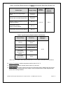
ENERGY STAR® Program Requirements
Product Specification for
Computer Servers
Test Method
Rev. Apr-2013
1 OVERVIEW
The following test method shall be used for determining compliance with requirements in the ENERGY
STAR Product Specification for Computer Servers and when acquiring test data for reporting of Idle State
power and Active State power on the ENERGY STAR Power and Performance Data Sheet.
2 APPLICABILITY
The following test method is applicable to all products eligible for qualification under the ENERGY STAR
Product Specification for Computer Servers.
3 DEFINITIONS
Unless otherwise specified, all terms used in this document are consistent with the definitions contained
in the ENERGY STAR Product Specification for Computer Servers.
4 TEST SETUP
A) Input Power: Input power shall be as specified in Table 1 and Table 2. The frequency for input power
shall be as specified in Table 3.
Table 1: Input Power Requirements for Products with Nameplate Rated Power Less Than or
Equal to 1500 watts (W)
Product Type
Supply Voltage
Servers with alternating current (ac)direct current (dc) Single-Output
Power Supply Units (PSUs)
230 volts (V) ac
or 115 V ac*
Servers with ac-dc Multi-Output PSUs
230 V ac or
115 V ac*
Optional Testing Conditions For ac-dc
(Japanese Market)
100 V ac
Three-phase Servers (North American
Market)
208 V ac
Three-phase Servers (Europe Market)
400 V ac
Voltage
Tolerance
Maximum Total
Harmonic
Distortion
+/- 1.0 %
2.0 %
ENERGY STAR Program Requirements for Computer Servers –Test Method (Rev. Apr-2013)
Page 1 of 7
Table 2: Input Power Requirements for Products with Nameplate Rated Power Greater Than
1500 W
Product Type
Supply Voltage
Servers with ac-dc Single-Output
PSUs
230 V ac or
115 V ac*
Servers with ac-dc Multi-Output PSUs
230 V ac or
115 V ac*
Optional Testing Conditions For ac-dc
(Japanese Market)
100 V ac
Three-phase Servers
(North American Market)
208 V ac
Three-phase Servers (Europe Market)
400 V ac
Voltage
Tolerance
Maximum Total
Harmonic
Distortion
+/- 4.0 %
5.0 %
Table 3: Input Frequency Requirements for All Products
Supply Voltage
Frequency
100 V ac
50 hertz (Hz) or
60 Hz
115 V ac
60 Hz
230 V ac
50 Hz or 60 Hz
Frequency
Tolerance
±1.0%
Three-phase
(North American
Market)
Three-phase
(Europe Market)
60 Hz
50 Hz
* Note: 230 V ac refers to the European market and 115 V ac refers to the North American market
B) Ambient Temperature: Ambient temperature shall be within 25 ± 5 °C.
C) Relative Humidity: Relative humidity shall be within 15% and 80%.
D) Power Analyzer: The power analyzer shall report true Root Mean Square (RMS) power and at least
two of the following measurement units: voltage, current, and power factor. Power analyzers shall
possess the following attributes:
ENERGY STAR Program Requirements for Computer Servers – Test Method (Rev. Apr-2013)
Page 2 of 7
1) Compliance: The power analyzer shall be chosen from the list of power measuring devices
TM1
2
specified in the Server Efficiency Rating Tool (SERT)
Design Document 1.0.0 .
2) Calibration: The analyzer shall have been calibrated within a year of the test date, by a standard
traceable to the National Institute of Science and Technology (USA) or a counterpart national
metrology institute in other countries.
3) Crest Factor: An available current crest factor of 3 or more at its rated range value. For analyzers
that do not specify the current crest factor, the analyzer must be capable of measuring an
amperage spike of at least 3 times the maximum amperage measured during any 1 second
sample.
4) Minimum Frequency Response: 3.0 kHz.
5) Minimum Resolution:
a) 0.01 W for measurement values less than 10 W;
b) 0.1 W for measurement values from 10 W to 100 W; and
c) 1.0 W for measurement values greater than 100 W.
6) Logging: The reading rate supported by the analyzer shall be at least 1 set of measurements per
second, where set is defined as a power measurement, in watts. The data averaging interval of
the analyzer shall equal the reading interval. Data averaging interval is defined as the time period
over which all samples captured by the high-speed sampling electronics of the analyzer are
averaged to provide the measurement set.
7) Measurement Accuracy: Power measurements shall be reported by the analyzer with an overall
accuracy of 1% or better for all measured power values.
E) Temperature Sensor: The temperature sensor shall possess the following attributes:
1) Compliance: The temperature sensor shall be chosen from the list of temperature measuring
devices specified in the SERT Design Document 1.0.0.
2) Logging: The sensor shall have a minimum reading rate of 4 samples per minute.
3) Measurement Accuracy: Temperature must be measured no more than 50mm in front of (upwind
of) the main airflow inlet of the Unit Under Test (UUT) and reported by the sensor with an overall
accuracy of ± 0.5 °C or better.
F) Active State Test Tool: SERT 1.0.0, provided by Standard Performance Evaluation Corporation
3
(SPEC) .
G) Controller System: The Controller System may be a Server, a desktop computer, or a laptop and shall
be used to record power and temperature data.
1) The power analyzer and the temperature sensor shall be connected to the Controller System.
2) The Controller System and the UUT shall be connected to each other via an Ethernet network
switch.
H) General SERT Requirements: Any additional requirements specified in any SPEC or SERT 1.0.0
supporting documents shall be followed, unless otherwise specified in this test method. Supporting
documents from SPEC include:
1) SPEC Power and Performance Methodology
2) SPEC Power Measurement Setup Guide
3) SPEC PTDaemon Design Document
1
http://www.spec.org/sert/
http://www.spec.org/sert/docs/SERT-Design_Document.pdf
3
http://www.spec.org/
2
ENERGY STAR Program Requirements for Computer Servers – Test Method (Rev. Apr-2013)
Page 3 of 7
4) SERT Design Document
5) SERT Run and Reporting Rules
6) SERT User Guide
7) SERT JVM Options
8) SERT Result File Fields
5 TEST CONDUCT
5.1 Test Configuration
Power and efficiency shall be tested and reported for the Computer Servers being tested. Testing shall be
conducted as follows:
A) As-shipped Condition: Products shall be tested in their “as-shipped” configuration, which includes
both hardware configuration and system settings, unless otherwise specified in this test method.
Where relevant, all software options shall be set to their default condition.
B) Measurement Location: All power measurements shall be taken at a point between the ac power
source and the UUT. No Uninterruptible Power Supply (UPS) units may be connected between the
power meter and the UUT. The power meter shall remain in place until all Idle and Active State power
data are fully recorded. When testing a Blade System, power shall be measured at the input of the
Blade Chassis (i.e., at the power supplies that convert data center distribution power to Chassis
distribution power).
C) Air Flow: Purposefully directing air in the vicinity of the measured equipment in a way that would be
inconsistent with normal data center practices is prohibited.
D) Power Supplies: All PSUs shall be connected and operational.
1) UUTs with Multiple PSUs: All power supplies shall be connected to the ac power source and
operational during the test. If necessary, a Power Distribution Unit (PDU) may be used to connect
multiple power supplies to a single source. If a PDU is used, any overhead electrical use from the
PDU shall be included in the power measurement of the UUT. When testing Blade Servers with
half-populated Chassis configurations, the power supplies for the unpopulated power domains
can be disconnected (see section 5.2.D)2) for more information).
E) Power Management and Operating System: The as-shipped operating system or a representative
operating system shall be installed. Products that are shipped without operating systems shall be
tested with any compatible operating system installed. For all tests, the power management
techniques and/or power saving features shall be left as-shipped. Any power management features
which require the presence of an operating system (i.e. those that are not explicitly controlled by the
Basic Input Output System (BIOS) or management controller) shall be tested using only those power
management features enabled by the operating system by default.
F) Storage: Products shall be tested for qualification with at least one Hard Disk Drive (HDD) or one
Solid State Drive (SSD) installed. Products that do not include pre-installed hard drives (HDD or SSD)
shall be tested using a storage configuration used in an identical model for sale that does include preinstalled hard drives. Products that do not support installation of hard drives (HDD or SSD) and,
instead, rely exclusively on external storage solutions (e.g. storage area network) shall be tested
using external storage solutions.
ENERGY STAR Program Requirements for Computer Servers – Test Method (Rev. Apr-2013)
Page 4 of 7
G) Blade System and Dual/Multi-Node Servers: A Blade System or Dual/Multi-Node Server shall have
identical configurations for each node or Blade Server including all hardware components and
software/power management settings. These systems shall also be measured in a way that ensures
all power from all tested nodes/Blade Servers is captured by the power meter during the entire test.
H) Blade Chassis: The Blade Chassis, at a minimum, shall have power, cooling, and networking
capabilities for all the Blade Servers. The Chassis shall be populated as specified in section 5.2.D).
All power measurements for Blade Systems shall be made at the input of the Chassis.
I)
BIOS and UUT System Settings: All BIOS settings shall remain as-shipped unless otherwise
specified in the test method.
J) Input/Output (I/O) and Network Connection: The UUT shall have at least one port connected to an
Ethernet network switch. The switch shall be capable of supporting the UUT’s highest and lowest
rated network speeds. The network connection shall be live during all tests, and, although the link
shall be ready and able to transmit packets, no specific traffic is required over the connection during
testing. For the purpose of testing ensure the UUT offers at least one Ethernet port (using a single
add-in card only if no onboard Ethernet support is offered).
1) Ethernet Connections: Products shipped with support for Energy Efficient Ethernet (compliant
with IEEE 802.3az) shall be connected only to Energy Efficient Ethernet compliant network
equipment during testing. Appropriate measures shall be taken to enable EEE features on both
ends of the network link during all tests.
5.2 UUT Preparation
A) The UUT shall be tested with the processor sockets populated as specified in Section 6.1.2 of
ENERGY STAR Eligibility Criteria Version 2.0.
B) Install the UUT in a test rack or location. The UUT shall not be physically moved until testing is
complete.
C) If the UUT is a Multi-node system, the UUT shall be tested for per node power consumption in the
fully-populated Chassis configuration. All Multi-node Servers installed in the Chassis shall be
identical, sharing the same configuration.
D) If the UUT is a Blade System, the UUT shall be tested for Blade Server power consumption in the
half-populated Chassis configuration with an additional option of testing the UUT in the fullypopulated Chassis configuration. For Blade Systems, populate the Chassis as follows:
1) Individual Blade Server Configuration
a) All Blade Servers installed in the Chassis shall be identical, sharing the same configuration
(homogeneous).
2) Half Chassis Population (Required)
a) Calculate the number of Blade Servers required to populate half the number of Single-wide
Blade Server slots available in the Blade Chassis.
b) For Blade Chassis having multiple power domains, choose the number of power domains
that is closest to filling half of the Chassis. In a case where there are two choices that are
equally close to filling half of the Chassis, test with the domain or combination of domains
which utilize a higher number of Blade Servers.
Example 1: A certain Blade Chassis supports up to 7 Single-wide Blade Servers on two
power domains. One power domain supports 3 Blade Servers and the other supports 4
ENERGY STAR Program Requirements for Computer Servers – Test Method (Rev. Apr-2013)
Page 5 of 7
Blade Servers. In this example, the power domain which supports 4 Blade Servers would
be fully populated during testing, while the other power domain would remain
unpopulated.
Example 2: A certain Blade Chassis supports up to 16 Single-wide Blade Servers on four
power domains. Each of the four power domains supports 4 Blade Servers. In this
example, two of the power domains would be fully populated during testing, while the
other two power domains would remain unpopulated.
c) Follow all user manual or manufacturer recommendations for partially populating the Chassis,
which may include disconnecting some of the power supplies and cooling fans for the
unpopulated power domains.
d) If user manual recommendations are not available or are incomplete, then use the following
guidance:
i.
Completely populate the power domains.
ii.
If possible, disconnect the power supplies and cooling fans for unpopulated power
domains.
iii. Fill all empty bays with blanking panels or an equivalent airflow restriction for the duration
of testing.
3) Full Chassis Population (Optional)
a) Populate all available Chassis bays. All power supplies and cooling fans shall be connected.
Proceed with all required tests in the test procedure as specified in Section 6.
E) Connect the UUT to a live Ethernet (IEEE 802.3) network switch. The live connection shall be
maintained for the duration of testing, except for brief lapses necessary for transitioning between link
speeds.
F) The Controller System required to provide SERT workload harness control, data acquisition, or other
UUT testing support shall be connected to the same network switch as the UUT and satisfy all other
UUT network requirements. Both the UUT and Controller System shall be configured to communicate
via the network.
G) Connect the power meter to an ac voltage source set to the appropriate voltage and frequency for the
test, as specified in Section 4.
H) Plug the UUT into the measurement power outlet on the power meter following the guidelines in
5.1.B).
I)
Connect the data output interface of the power meter and the temperature sensor to the appropriate
input of the Controller System.
J) Verify that the UUT is configured in its as–shipped configuration.
K) Verify that the Controller System and UUT are connected on the same internal network via an
Ethernet network switch.
L) Use a normal ping command to verify that the Controller System and UUT can communicate with
each other.
4
M) Install SERT 1.0.0 on the UUT and the Controller System as specified in the SERT User Guide 1.0.0 .
4
http://www.spec.org/sert/docs/SERT-User_Guide.pdf
ENERGY STAR Program Requirements for Computer Servers – Test Method (Rev. Apr-2013)
Page 6 of 7
6 TEST PROCEDURES FOR ALL PRODUCTS
6.1 Idle State Testing
A) Power on the UUT, either by switching it on or connecting it to mains power.
B) Power on the Controller System.
C) Begin recording elapsed time.
D) Between 5 and 15 minutes after the completion of initial boot or log in, set the power meter to begin
accumulating idle power values at an interval of greater than or equal to 1 reading per second.
E) Accumulate idle power values for 30 minutes. The UUT shall maintain in Idle State throughout this
period and shall not enter lower power states with limited functionality (e.g., sleep or hibernate).
F) Record the average idle power (arithmetic mean) during the 30 minute test period.
G) When testing a Multi-node or Blade System, proceed as follows to derive single node or single Blade
Server power:
1) Divide the measured total idle power in Section 6.1.F) by the number of nodes/Blade Servers
installed for the test;
2) Record the measured total and per-node/per-Blade Server power values as calculated in 6.1.G)1)
for each measurement.
6.2 Active State Testing Using SERT
A) Reboot the UUT.
B) Between 5 and 15 minutes after the completion of initial boot or log in, follow the SERT User Guide
1.0.0 to engage SERT.
C) Follow all steps outlined in the SERT User Guide 1.0.0 to successfully run SERT.
1) Manual intervention or optimization to the Controller System, UUT, or its internal and external
environment is prohibited during the execution of SERT.
D) Once SERT is completed, include the following output files with all testing results:
1) Results.xml
2) Results.html
3) Results.txt
4) All results-chart png files (e.g. results-chart0.png, results-chart1.png, etc.)
5) Results-details.html
6) Results-details.txt
7) All results-details-chart png files (e.g. results-details-chart0.png, results-details-chart1.png, etc.)
ENERGY STAR Program Requirements for Computer Servers – Test Method (Rev. Apr-2013)
Page 7 of 7