1
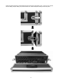
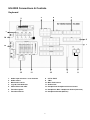
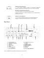
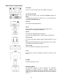
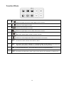
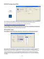
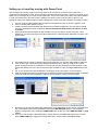
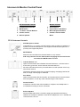
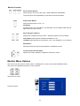
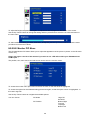
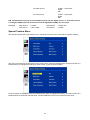
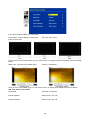
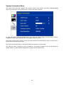
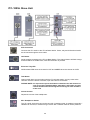
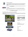
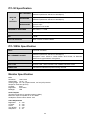
Mobile Video Studio HS-2000 Hand Carried Studio (SE-2000+ITC-50+TLM-170) Instruction Manual Rev 250110 www.datavideo-tek.com Contents Warnings and Precautions ............................................................................................................................... 3 Warranty ........................................................................................................................................................... 4 Disposal ............................................................................................................................................................ 4 What is in the Package ..................................................................................................................................... 4 Introduction ....................................................................................................................................................... 4 Unpacking the HS-2000 ................................................................................................................................... 5 HS-2000 Connections & Controls..................................................................................................................... 7 Keyboard ................................................................................................................................................... 7 Keyboard Controls ..................................................................................................................................... 8 Rear Panel............................................................................................................................................... 11 Rear Panel Connections ......................................................................................................................... 12 Main Source and Sub Source Rails ........................................................................................................ 13 Transition Effects ..................................................................................................................................... 14 System Configuration Menu .................................................................................................................... 15 USER’S PROFILE .............................................................................................................. 15 INPUT SETTINGS .............................................................................................................. 15 PIP SETTING...................................................................................................................... 16 LUMA SETTING ................................................................................................................. 16 LOGOS ............................................................................................................................... 16 MODE SETTING................................................................................................................. 17 MONITOR MODE ............................................................................................................... 17 INPUT 4 MODE .................................................................................................................. 17 MASTER USER SETTING ................................................................................................. 17 SOFT EDGE ....................................................................................................................... 17 AUTO TAKE SPEED .......................................................................................................... 17 BACKGROUND .................................................................................................................. 18 BLACK & BARS POS.RIGHT ............................................................................................. 18 FACTORY SETTINGS ........................................................................................................ 18 CLOCK SETTINGS............................................................................................................. 18 Audio Inputs and Levels .......................................................................................................................... 19 HS-2000 Configuration Utility .................................................................................................................. 20 Storing New Logos .................................................................................................................................. 20 Setting up a Luma Key overlay with Power Point ................................................................................... 21 HD-SDI Cabling Advice ........................................................................................................................... 22 Intercom & Monitor Control Panel .................................................................................................................. 23 Monitor Function ............................................................................................................................................. 24 Menu Options ............................................................................................Error! Bookmark not defined. Colour Processor ..................................................................................................................................... 25 PIP Menu ................................................................................................................................................. 26 Special Feature Menu ............................................................................................................................. 27 ITC-100SL Slave Unit ..................................................................................................................................... 30 Optional Datavideo Accessory Items for the HS-2000 ................................................................................... 31 HS-2000 (SE-2000) Specification................................................................................................................... 32 ITC-50 Specification ....................................................................................................................................... 33 ITC-100SL Specification ................................................................................................................................. 33 Monitor Specification ...................................................................................................................................... 33 Service & Support ........................................................................................................................................... 34 2 Warnings and Precautions 1. Read all of these warnings and save them for later reference. 2. Follow all warnings and instructions marked on this unit. 3. Unplug this unit from the wall outlet before cleaning. Do not use liquid or aerosol cleaners. Use a damp cloth for cleaning. 4. Do not use this unit in or near water. 5. Do not place this unit on an unstable cart, stand, or table. The unit may fall, causing serious damage. 6. Slots and openings on the cabinet top, back, and bottom are provided for ventilation. To ensure safe and reliable operation of this unit, and to protect it from overheating, do not block or cover these openings. Do not place this unit on a bed, sofa, rug, or similar surface, as the ventilation openings on the bottom of the cabinet will be blocked. This unit should never be placed near or over a heat register or radiator. This unit should not be placed in a built-in installation unless proper ventilation is provided. 7. This product should only be operated from the type of power source indicated on the marking label of the AC adapter. If you are not sure of the type of power available, consult your Datavideo dealer or your local power company. 8. Do not allow anything to rest on the power cord. Do not locate this unit where the power cord will be walked on, rolled over, or otherwise stressed. 9. If an extension cord must be used with this unit, make sure that the total of the ampere ratings on the products plugged into the extension cord do not exceed the extension cord’s rating. 10. Make sure that the total amperes of all the units that are plugged into a single wall outlet do not exceed 15 amperes. 11. Never push objects of any kind into this unit through the cabinet ventilation slots, as they may touch dangerous voltage points or short out parts that could result in risk of fire or electric shock. Never spill liquid of any kind onto or into this unit. 12. Except as specifically explained elsewhere in this manual, do not attempt to service this product yourself. Opening or removing covers that are marked “Do Not Remove” may expose you to dangerous voltage points or other risks, and will void your warranty. Refer all service issues to qualified service personnel. 13. Unplug this product from the wall outlet and refer to qualified service personnel under the following conditions: a. When the power cord is damaged or frayed; b. When liquid has spilled into the unit; c. When the product has been exposed to rain or water; d. When the product does not operate normally under normal operating conditions. Adjust only those controls that are covered by the operating instructions in this manual; improper adjustment of other controls may result in damage to the unit and may often require extensive work by a qualified technician to restore the unit to normal operation; e. When the product has been dropped or the cabinet has been damaged; f. When the product exhibits a distinct change in performance, indicating a need for service. 3 Warranty Standard Warranty x Datavideo equipment is guaranteed against any manufacturing defects for one year from the date of purchase. x The original purchase invoice or other documentary evidence should be supplied at the time of any request for repair under warranty. x Damage caused by accident, misuse, unauthorized repairs, sand, grit or water is not covered by this warranty. x All mail or transportation costs including insurance are at the expense of the owner. x All other claims of any nature are not covered. x Cables & batteries are not covered under warranty. x Warranty only valid within the country or region of purchase. x Your statutory rights are not affected. Two Year Warranty x All Datavideo products purchased after 01-Oct.-2008 qualify for a free one year extension to the standard Warranty, providing the product is registered with Datavideo within 30 days of purchase. For information on how to register please visit www.datavideo-tek.com or contact your local Datavideo office or authorized Distributors x Certain parts with limited lifetime expectancy such as LCD Panels, DVD Drives, Hard Drives are only covered for the first 10,000 hours, or 1 year (whichever comes first). x Any second year warranty claims must be made to your local Datavideo office or one of its authorized Distributors before the extended warranty expires. Disposal For EU Customers only - WEEE Marking. This symbol on the product indicates that it will not be treated as household waste. It must be handed over to the applicable take-back scheme for the recycling of electrical and electronic equipment. For more detailed information about the recycling of this product, please contact your local Datavideo office. What is in the Package 1 4 4 4 4 1 4 1 x x x x x x x x Gooseneck Microphone MC-1 Headphone ITC-100SL Tally LED TD-1 with Black Velcro 36cm CB-3 XLR Cable + CON 20M AC Power Cord 3.5Ø earphone (M) to earphone (F) L: 17cm HS-2000 Instruction Manual Introduction Editing, monitoring and communication are all in one box. Datavideo HS-2000 mobile video studio is a ready to go solution; it saves a lot of your valuable time when setting up or breaking down in the field. To get the most out of your HS-2000 please read this user manual, and the other user manuals supplied with it, and familiarise yourself with its many features. 4 Unpacking the HS-2000 Place the HS-2000 on a stable, flat surface, such as a desk with the two locks of the case facing towards you. Unlock the two locks and lift the lid. 5 Open the locking catches on both sides and remove the rear connections cover. You can now connect source cabling, output cabling, AC power and the ITC-100SL belt pack cabling to this rear panel. 6 HS-2000 Connections & Controls Keyboard 3 2 4 5 1 14 6 7 13 12 1. 2. 3. 4. 5. 6. 7. 11 Audio input selectors / Level Controls Audio meters Menu and Controls Logo & Clock Selection Video Effect: PIP / KEY Transition Speed Transition Effects 10 8. 9. 10. 11. 12. 13. 14. 7 9 8 CUT & TAKE T-Bar Main / Sub Source Audio mixer Headphone & Headphone Volume Control Headphone / MIC / Headphone Socket (Intercom) Headphone Socket (Monitor) Keyboard Controls Audio Input Source Selectors and Level Controls This section of the HS-2000 controls which audio input channel (CH1~CH4) will be sent to the Audio Bus and its associated Fader. This row of audio channel selection buttons has LEDs built in to show which input channel is active. Level control for each audio input source is via the rotary pots above each of the audio channel selection buttons. A+V: When this button is engaged or lit, the audio associated with a selected video input source automatically follows the video through any transition between the Main and Sub Sources. When the A+V button is inactive, the audio sources must be switched manually. For more information, see A+V (Page 19). Audio LED Meters These meters play a vital part in correctly setting the audio levels to avoid clipping or other distortion. The LED style Audio meters, show the signal strength at the Audio Output. The signal they measure is determined by the sources selected by the Audio Bus selectors and the levels set by the rotary pots and faders. Audio Monitor Button Use the Headphone section to accurately monitor any of the sources (CH1, CH 2, CH3, CH4) or “Master” output. Repeated presses of the Headphone Audio Monitor button will cycle through the monitoring choices. In many cases, headphones may be a more useful and accurate choice than speakers for audio monitoring. System Configuration Menu Press the Menu button in the HS-2000 function section to enter the System Configuration Menu. Press the up, down, left, and right arrow buttons to navigate the menu options and to change values. Use the ENT button to save and confirm any setting that has been amended. Logo Setting Press the Logo1, Logo2 or Clock buttons to display the selected function on the PVW and PGM screens. See Storing New Logos (Page 20) Logo1 and Logo2 or Logo1 and the Clock can both be selected at the same time. Logo2 and the Clock cannot be selected/displayed at the same time. 8 PIP / KEY LUMA PVW and LUMA PGM A Luma key can be performed between 2 inputs and the result sent to the PVW and PGM display channels. See Setting up a LUMA Key (Page 21) SET If you want to enable the PIP function, you must first press the SET key, then press the PIP PVW key and then select the Sub Source channel for the PIP window. The size and position of the window can be set within the System Configuration Menu. See PIP SETTING (Page 16) PIP PVW Allows the user to see what the PIP window will look like and make any adjustments before the PIP window is taken to the PGM output. Pressing the PIP PVW button toggles the PIP window on and off using a simple dissolve. PIP PGM Once the PIP window is ready to be taken to air the PIP PGM button will allow a simple dissolve in and out over the top of the current program output. Transition Speed Five buttons used to choose different speeds for a transition effect when using the TAKE button to switch between PVW and PGM sources. Transition Effects There are 10 Transition Effects keys. Six of these keys relate to the available types of WIPE effect. INV (Invert) changes the direction of the chosen WIPE. SFT changes the softness of the WIPE edge. FRZ freezes the current PGM image until toggled off or CUT away. MIX is a dissolve effect between the PVW and PGM sources. For more information, see Transition Effects (Page 14). CUT Forces an immediate switch between the selected main and sub sources. The selected sub source becomes the main program output with no transition effect applied. TAKE Starts an automated switch between the main and sub sources. The selected sub source becomes the main program output with the selected Transition Effect applied at the selected Effect Speed. 9 T-Bar The T-Bar is used to carry out a manual transition such as a wipe, fade, mix or key. When it has travelled as far as it can go the transition is complete. Calibrating the T-bar: 1. Turn the HS-2000 Power Off. 2. Press and hold in key SET and button 1 on the Sub Source row. 3. Turn the HS-2000 Power back On. 4. Keyboard indication power-up test begins. Wait until the test ends and key SET and Sub Source button 1 remain lit, then release these 2 keys. 5. Move the T-bar to its lowermost position and then move it slightly up about 1 to 2mm. 6. Press the CUT key. The PVW LED will light up. 7. Move the T-bar to its uppermost position and then move it slightly down about 1 to 2mm. 8. Press the TAKE key. The AIR LED will light up. 9. Press the SET key to return to the HS-2000 to operational mode. WARNING: If you do not follow the T-Bar calibrating steps correctly the T-Bar may work incorrectly. Main Source Used to select which of the source input channels or backgrounds that are sent to the Main video PROGRAM output. Sub Source Used to select which of the source input channels or backgrounds will be transitioned to or used as a sub source in an effect such as PIP. Audio mixer These CH1~CH4 Audio Level Faders are for controlling the CH1~CH4 audio mix. These faders correspond to the Audio Source selector buttons and control the relative volume of each input in the master output as well as the master output level. They are called faders because they are used to decrease (rather than increase) the signal levels to create a balanced and pleasing mix. When the CH1~CH4 Audio Level Faders are set at -6dB, or Unity, they pass the audio signal through at the same level as when it entered the bus. This is why the level setting at the Input Bus is so important. MASTER This Slider is for controlling the audio level for the Mixed audio output. Headphone Accepts a stereo mini jack plug for stereo headphones. Used with the Audio Monitor Button. The headphone volume is adjusted by the rotating Head phone volume control. Headphone Volume Control Controls Headphone volume level. Use the Headphone section to accurately monitor any of the sources ( CH1, CH2, CH3, CH4 or “Master” ) output. 10 Headphone Socket (Intercom) ¼ “/ 6.3mm Stereo Headphone Socket for conventional headphones. Plugging in headphones will disable the built-in ITC-50 Intercom speaker Microphone / Headset Socket (Intercom) 3.5mm Stereo Socket for combined Microphone Headset. Plugging in a Microphone / Headset will disable the built-in speaker and the XLR Microphone Input. Headphone Socket (Monitor) ¼ “/ 6.3mm Stereo Headphone Socket for conventional headphones. Plugging in headphones will disable the built-in monitor speakers. Rear Panel 13 1 1. 2. 3. 4. 5. 6. 7. 12 2 3 4 5 11 6 HD- SDI INPUTS 1~3 HD- SDI IN or DVI-D IN DVI-D IN TALLY Output RS-232 HD- SDI PGM OUT HD- YUV PGM OUT 10 7 8. AC INPUT 100~240V 2.5A 50~60HZ 9. POWER ON / OFF 10. MONITOR HDMI IN ** 11. AUDIO OUT 12. AUDIO IN 13. TO ITC-100SL BELTPACK ** Note : The HDMI input is for confidence monitoring only and cannot be mixed 11 9 8 Rear Panel Connections HD- SDI IN Inputs 1 to 3 are HD-SDI inputs only on BNC connections. HD- SDI IN / DVI-D IN Input 4 has a choice of two connections HD-SDI (via BNC) or DVI-D. You select the connection you wish to use - for more information, see INPUT 4 MODE (Page 17). DVI-D IN DVI-I Signal Input (Digital Input 5). TALLY Tally out socket. This supplies tally light information to the Datavideo ITC-50 system (not supplied). RS-232 9-pin serial port standard RS-232 interface. Connect PC to update firmware, Logos or Mixer Configuration. HD- SDI OUT 4:2:2 SDI Video data supports SMPTE 292M standard at 1.5G bps. SDI transfers professional level video signals and it’s can connect to long distance transmission systems. HD- YUV OUT HD- YUV component analogue output connectors. AC IN AC in socket connect the supplied 100~240V 2.5A PSU to this socket. POWER Switches the power On / Off. MONITOR HDMI IN The HS-2000 provides a useful connection for confidence monitoring of HDMI sources on location. However, this connection cannot be mixed. Instead use a DAC-9 to convert the HDMI source to HD-SDI and then the source can be mixed via inputs 1~4. 12 AUDIO OUT Supports two channels XLR Balanced Audio output. AUDIO IN The HS-2000 supports four XLR Balanced Audio Input channels. There are two kinds of switches under AUDIO IN: LINE/MIC switch is used to set the audio as LINE in or MIC in. When LINE in is selected please also set the 48V ON/OFF switch to OFF in order to prevent burn-out damage to the circuit. The 48V ON/OFF switch is for phantom power. If you want to use MIC in, please set the LINE/MIC switch first, and then if using a Condenser microphone turn ON the 48V ON/OFF switch. If you wish to use a Dynamic microphone please turn OFF the 48V ON/OFF switch. TO BELTPACK (For Intercom) Channel Input / Output XLR Sockets Each of the 5 channels has an XLR connector that carries bidirectional signals between the ITC-50 and ITC-100SL. All connections are contained within the one cable. Main Source and Sub Source Rails The Main Source Rail shows the active channel, this is the Live output. The active channel will also appear as the Program Output (PGM). You can immediately switch or CUT from one input channel to another directly on the Main Source Rail, you will see the PROGRAM Output switch as you press different keys along this rail. As each key is selected or pressed it will turn Red. The Sub Source Rail shows the Cued channel, the selected channel will appear in the Preview window. The selected key will turn Yellow. The Sub Source selection determines which input will be transitioned to when using any of the transition controls and provides the Sub Source video for Picture in Picture and Key functions. 13 Transition Effects 1 WIPE from upper Left corner to lower Right corner of screen 2 WIPE from Left to Right of screen 3 WIPE from Top to Bottom of screen 4 WIPE from upper Right corner to lower Left corner of screen 5 WIPE from outside edge of screen to centre of screen 6 WIPE from Left and Right hand sides into the centre of the screen. 7 SFT Controls the border softness of the WIPE or effect. 8 MIX 9 INV Inverts the WIPE direction – the chosen WIPE moves in the opposite direction. 10 FRZ This freezes the PGM video, press it again, and it returns to the selected Live PGM source. Also known as a fade or dissolve, is a transition where all the pixels of one source are replaced by all the pixels of another, at a smooth rate, and at the same time. 14 System Configuration Menu Menu and Navigation Press the MENU button in the Function section of the HS-2000’s keyboard to enter the System Configuration Menu. The menu will be displayed on the HS-2000’s Multi Preview output as below. Press the UP, DOWN, LEFT and RIGHT arrow buttons to highlight or select a menu option. Then use the UP and DOWN arrow buttons to change the value of the selected item or option. Press the ENT button to Enter and save your chosen value for the selected menu item. USER’S PROFILE - Press the MENU button and highlight the USER’S PROFILE option. - Press the arrow RIGHT button and select a profile number by using the UP and DOWN arrows. - Press the ENT button to confirm the chosen profile number to be used. The current user will also be confirmed between PREVIEW and PROGRAM windows on the Multi Preview Display. - Up to 6 User Profiles can be configured and saved. These profiles are numbered 0 ~ 5. User’s Profile 0 is also referred to as the BASIC or MASTER USER settings profile. If there are settings that will be common to all user profiles 1 ~ 5 then they are set here first under BASIC and then these common settings can be copied to the other user profiles (1 ~ 5) by selecting LINK TO BASIC. Then while adjusting USER 1 ~ 5, you can refer to the BASIC settings, thus avoiding multiple and repeated adjustments for all remaining user profiles. - Any changes made to the HS-2000’s configuration will be saved to the currently selected profile. The default user profile at Power On is the last selected profile used. INPUT SETTINGS - Press the MENU button and highlight the INPUT SETTINGS option. - Press the arrow buttons to select an item and press the ENT to confirm the setting. - BRIGHTNESS: adjustment range from -7 to +7 - CONTRAST: adjustment range from -7 to +7 - SATURATION: adjustment range from -7 to +7 - MASTER USER SETTING: When selected, the values for the above are copied from the BASIC profile. 15 PIP SETTING - Press the MENU button and highlight the PIP SETTING. - Press the arrow buttons to select an item and press the ENT to confirm the setting. - X- POSITION: adjustment range from 0 to +102 (when MODE SETTING is 1080i) - Y- POSITION: adjustment range from +113 to 0 (when MODE SETTING is 1080i) - X- POSITION: adjustment range from 0 to +70 (when MODE SETTING is 720p) - Y- POSITION: adjustment range from +77 to 0 (when MODE SETTING is 720p) - SIZE: adjusts the size of the smaller PIP window using a range from +1 to +97 - MASTER USER SETTING: When selected, the values for the above are copied from the BASIC profile. If you want to enable the PIP function, you must first press the SET key in the PIP / KEY section of the HS-2000 keyboard, then press the PIP PVW key and then select the Sub Source channel required for the PIP window. The PIP window will appear on the PREVIEW and PROGRAM displays when PiP PVW and PiP PGM buttons are lit on the HS-2000’s Keyboard. LUMA SETTING - Press the MENU button and highlight the LUMA SETTING option. - Press the arrow buttons to select an item and press the ENT to confirm the setting. - You can set the value for the LUMA LEVEL (0 Black to 255 White) - This LUMA LEVEL keys out a grey scale range between 0 and the LUMA LEVEL value set. - So LUMA LEVEL 20 would key out a range of Black between 0 and 20 from the PGM source. - MASTER USER SETTING: When selected, the value for the above is copied from the BASIC profile. LOGOS - Press the MENU button and highlight the LOGOS option. - Press the arrow buttons to select an item and press the ENT to confirm the setting. - You can select a pre-loaded Logo from the HS-2000’s 14 memory slots for Logo1 and Logo2. - You can set the on screen positions of Logo1, Logo2 and the Clock. - X- POSITION: adjustment range from 0 to +114 (under 1080i) - Y- POSITION: adjustment range from +112 to 0 (under 1080i) - X- POSITION: adjustment range from 0 to +72 (under 720p) - Y- POSITION: adjustment range from +150 to 0 (under 720p) - Accepted Logo sizes 256x192 pixels, 512x96 pixels or 128x384 pixels - MASTER USER SETTING: When selected, the values for the above are copied from the BASIC profile. Logos need to be loaded into the 14 memory slots in preparation before an event – See Storing New Logos (Page 20). 16 MODE SETTING - Press the MENU button and highlight the MODE SETTING. - Press the arrow buttons to select an item and press the ENT to confirm the setting. - This Mode setting is used to adjust the HD input mode. - HD Mode values can be 1080/50i - 1080/60i - 1080/59.94i - 720/50p - 720/60p or 720/59.94p - MASTER USER SETTING: When selected, the values for the above are copied from the BASIC profile. - Please ensure your HD input source(s) match the HD mode of the HS-2000. The selected HD mode is confirmed between the PREVIEW and PROGRAM windows on the Multi Preview Display. MONITOR MODE - Press the MENU button and highlight the MONITOR MODE option. - Press the arrow buttons to select an item and press the ENT to confirm the setting. - This mode adjusts the Multi Preview DVI-D output between 1080i 60Hz and 720p 60Hz. - MASTER USER SETTING: When selected, the values for the above are copied from the BASIC profile. INPUT 4 MODE - Press the MENU button and highlight the INPUT 4 MODE option. - Press the arrow buttons to select an input option and press the ENT to confirm the setting. - This mode is used to switch INPUT 4 from HD-SDI input to DVI-D input and vice versa. - MASTER USER SETTING: When selected, the values for the above are copied from the BASIC profile. The changed setting will also be confirmed between PREVIEW and PROGRAM windows on the Multi Preview Display. MASTER USER SETTING - Press the MENU button and highlight the MASTER USER SETTING option. - Press the arrow buttons to select an item and press the ENT to confirm the setting. - This mode is used to return the HS-2000 BASIC profile (USER 0) to its factory default settings. - If the BASIC profile is changed then any USER profiles (1 ~ 5) linked to BASIC will also be changed. SOFT EDGE - Press the MENU button and highlight the SOFT EDGE option. - Press the arrow buttons to select an item and press the ENT to confirm the setting. This mode is used to set the size of the soft border (SFT Key) when using a WIPE transition or the PIP effect. AUTO TAKE SPEED - Press the MENU button and highlight the AUTO TAKE SPEED option. - Press the arrow buttons to select an item and press the ENT to confirm the setting. - This adjusts the different speeds of the selected transition effect when the TAKE button is used. 17 BACKGROUND - Press the MENU button and highlight the BACKGROUND option. - Press the arrow buttons to select an item and press the ENT to confirm the setting. - This option sets the background colour of the Multi Preview screen – options are Black, Grey or Blue. BLACK & BARS POS.RIGHT - Press the MENU button and highlight the BLACK & BARS POS.RIGHT option. - Press the arrow buttons to select an item and press the ENT to confirm the setting. - This option allows the user to change the order of the keys on the Main and Sub Source rails. - When selected the order of the keys will be BLK, BAR, 1, 2, 3, 4, DVI instead of the original sequence. - Once changed the Key Cap Legends can be carefully removed and relocated to the new position. FACTORY SETTINGS - Press the MENU button and highlight the FACTORY SETTINGS option. - Press the arrow buttons to select an item and press the ENT to confirm the setting. - This menu option is used when it is required to return the product back to its factory state. - If you select this option then ALL user settings (BASIC and 1 to 5) are returned to their factory defaults. CLOCK SETTINGS - Press the MENU button and highlight the CLOCK SETTINGS. - Press the arrow buttons to select an item and press the ENT to confirm the setting. - This mode is used to set the clock within the HS-2000. The current Clock value is displayed in between the PREVIEW and PROGRAM windows of the Multi Preview Display. 18 Audio Inputs and Levels Analogue audio comes into the HS-2000 through the XLR connectors on the rear panel (see above diagram). The HS-2000 supports four XLR Balanced Audio Input channels. There are two kinds of switches next to each XLR input under AUDIO IN: The LINE/MIC switch is used to set the audio as LINE in or MIC in. When LINE in is selected please also set the 48V ON/OFF switch to OFF in order to prevent burn-out damage to the audio circuit/Mic*. The 48V ON/OFF switch is for Phantom power. If you want to use MIC in, please set the LINE/MIC switch first, and then if using a Condenser microphone* turn ON the 48V ON/OFF switch. If you wish to use a Dynamic microphone please turn OFF the 48V ON/OFF switch. *NOTE: Always double check the manual for the microphone being used to see what advice it gives regarding power as some MICs have internal batteries too. A+V The Audio Input Channel Selectors and Level pots are the first stage in the audio signal path. Each channel carries the audio associated with a video input channel. When the A+V button is active, the audio follows the video through a transition. This means that when this LED is lit, only one channel of the Audio input section (CH1, CH2, CH3, CH4) can be activated at a time. When the transition is a CUT, the audio will switch abruptly at the same time. Try this: With the A+V button engaged or lit, select Channel 2 on the Main Source bus (of course, you must have a valid video and audio source connected). Notice that CH2 is lit in the Audio Source section. Now, select channel 1 on the Sub Source bus. Work the T-Bar to manually perform a transition (if no specific transition is selected, the sources will dissolve) and watch Audio Input Source channel change from CH2 to CH1, following the video. When the A+V button is not engaged or off, you can manually select which of the 4 Audio input channels will be applied to the Video bus at the Fader. In fact, you have to select one or more of these channels, or there will be no audio present at the audio out connections. The A+V button should be inactive while doing level settings at the beginning-of-session so that you can select an input and adjust the initial level correctly. NOTE: Audio cannot be de-embedded by the HS-2000 from a HD-SDI input and Audio will not be embedded into the HS-2000’s HD-SDI PGM outputs. 19 HS-2000 Configuration Utility The Configuration Utility software allows a PC (running Windows XP Professional) to make changes to the mixer* Logos tab via the RS-232 port on the rear of the HS-2000 from the PC COM1 Serial port. This software Utility is free and can be downloaded from the following web page http://www.datavideo.info/en/Mixer%20-%20Switchers/SE-2000 Once downloaded, run the install wizard and follow the on-screen prompts. The installation will leave an Icon on the PC desktop as above. With the HS-2000 connected to the PC via an RS-232 cable, the initial utility screen will be displayed as above, when the program is launched. Storing New Logos The Configuration Utility software allows a Windows XP Professional PC to make changes to the Logos stored within the 14 memory slots of the HS-2000 mixer. This is done from the Logos tab shown below. New Logos to LOAD and WRITE into these memory slots MUST be a certain size. Accepted Logo sizes are 256x192 pixels, or 512x96 pixels, or 128x384 pixels. Your new Logos need to be created in a graphics software package first as a JPEG or BMP file. This 3rd party graphics software is not supplied by Datavideo. * We recommend that you only use the HS-2000 Configuration Utility to add/write new Logos as changing any other settings without guidance may cause the mixer or its set up menus to become un-usable. 20 Setting up a Luma Key overlay with Power Point The HS-2000 has 5 inputs. Input 5 is DVI only and this can be used to connect a DVI-D cable from a computer’s monitor/graphics card. The PC graphics card will need 2 connections 1 for the PC monitor and a spare DVI-D connection to go to input 5 on the HS-2000. The PC will need to have Microsoft Office installed in order for PowerPoint to be used. If all the settings are correct on the mixer and the PC then we can attempt to use this PC display output to create a simple text overlay using the HS-2000’s Luma Key function. 1. Connect a DVI-D cable between the HS-2000 and the spare DVI port on the PC’s graphics card. 2. Turn on the HS-2000 and then the PC. 3. Create a PowerPoint presentation with White text on a Black background. You may want to create your own Slide Master within PowerPoint. Use the PowerPoint Help function for advice on how to do this. 4. Check the Multi Preview Display on the HS-2000, can you see the PC output in the DVI VTR2 window? If you cannot see the PC’s output extend the PC’s desktop within Windows to monitor 2 as shown below. 5. PC screen size for monitor 2 should match the HD resolution, for example 1920x1080 or 1280x720. 6. If DVI VTR2 is just a blue screen (blue desktop background only), then try using the PC mouse pointer to drag a window or a desktop icon across and onto the HS-2000 DVI VTR2 window. It may help to also select DVI on the sub source rail of the HS-2000 so it is in the larger PREVIEW window too. 7. OK, so you should now have the Monitor 2 PC display running into input 5 on the HS-2000. 8. Open up Powerpoint on the PC and use Set Up Show so that the presentations play back on Monitor 2 (the HS-2000) and the presentator’s output is sent to Monitor 1 (the PC’s own monitor). 9. Now that you can see the presentation playing back in the PREVIEW window we can now attempt to key out the Black parts of the Presentation using the LUMA SETTING option in the HS-2000’s System Configuration menu whilst the LUMA PVW button is also ON. See LUMA SETTING on page 14 also. 10. Once you have the right LUMA SETTING or overlay effect in the PREVIEW window you can then press LUMA PGM key to toggle the overlay effect ON or OFF the main PROGRAM output. 21 HD-SDI Cabling Advice Start with good cabling. BNC coax cables and connectors are not all made to the same standard. From the thickness and grade of the centre conductor to the type of dielectric, all these factors contribute to impedance, attenuation and Return Loss (RL). Serial Digital Video coax like Belden 1694A or Canare L5CFB are good examples of broadcast quality SDI cable. A 75 Ohm (ȍ) impedance must be maintained throughout the HS-2000 SDI signal or cable path, including BNC connectors etc. Return Loss is the portion of the transmitted SDI signal that is not admitted to the receiver (mixer) and is then reflected back along the cable toward the transmitter (DAC-9). Reflections in the transmission path will cause attenuation as well as distortion of the SDI signal received. The signal is attenuated because part of it is reflected back and does not make it to the receiver (HS-2000 for example); it is also distorted because the reflected signal mixes with the original signal causing it to distort as well as adding to the noise floor. Care must also be taken with cable length, as it will affect the error rate in the SDI signal. Cable lengths beyond acceptable limits will see error rates reach a tipping point and this will bring about a total loss of picture also known as the Cliff Effect. Always check with your supplier for cabling advice on the maximum distance for a particular signal and data rate, in this case an SDI signal that complies with the SMPTE 292M standard at 1.5 Gbps. Datavideo Taiwan have determined that single BNC SDI cable (5CFB) runs of up to 100m should be possible with this unit before the signal would need to be re-clocked or repeated. Here is a basic list of other things to avoid • Do not step on or rest equipment on the cables. • Do not roll dollies or trolleys over the cables. • Do not put kinks or sharp bends in the cables. • Do not exceed the minimum bend radius of the cable. The general rule for an acceptable bend radius is 10 times the diameter of the cable. • Cable pulls should be done carefully – do not jerk or stretch the cable(s). Do not exceed the cable’s maximum pulling tension. (call the cable supplier / manufacturer for this information.) • Do not pull cable ties too tight on cable looms. If you cannot move any cable inside a loom tie, the tie is too tight. Put an extra piece of cable in when tightening loom ties - then remove it afterwards to create the space. • Do not put cable management fixings at standard distances apart. This can lead to deformity at a given wavelength, which can increase RL. Place your loom cable ties at random distances for the same reason. 22 Intercom & Monitor Control Panel 1 2 3 4 5 6 ITC-50 Intercom Controls 1. 2. 3. 4. 5. 7 8 9 Monitor Controls XLR Microphone Socket MUTE Button 1~5 & ALL Channel Buttons Volume Control Built-In Speaker 6. 7. 8. 9. Source Select Aspect Ratio & PIP Button Menu Navigation Buttons Volume Control & Audio Meter ITC-50 Intercom Controls XLR Microphone Socket Combined XLR / ¼” (6.3mm) Jack Microphone Input for either a Condenser or Dynamic Gooseneck Microphone. XLR supports Condenser Microphones ¼” (6.3mm) Jack supports Dynamic. MUTE Button Mutes all communication from the base station or any channel. N.B. If any channel uses the CALL button the paging tone will still sound even when the MUTE button is active. Channel Buttons 1~5 Opens communication with individual channels. More than 1 channel can be active at any given time, active channels are illuminated red. All active channels will hear any communication from the operator or from any other active channel. The buttons will also indicate if any channel is paging, the paging channel will flash in orange until the page is answered. ALL Button Opens communication with all channels. All channels will hear communication from the operator, or from any other channel using the TALK button. Volume Control Controls the Volume of the built-in speaker or outputs to the headphones or mic/headset according to what is connected Built-In Speaker Sounds audible alert when a channel is paging and provides audio during talkback conversations. Speaker is mute when headphones or mic / headset are connected to the ITC-50 23 Monitor Controls Source Select Buttons Select the type of input you are using - HDMI, PREVIEW, PROGRAM The active input will be indicated by a red LED on the Source Button Aspect Ratio Button Sets the Aspect Ratio to 16:9 / 4:3 PIP Button Activates Picture in Picture Mode - See PIP Menu for more details. Red LED will light when PIP mode is active. Menu Navigation Buttons Display and navigate the set up menus - See Menu Options for more details Down Button also switches the Safe Area Mask On / Off UP Button also switches the 4:3 Mask On / Off - (only available in 16:10 modes) Mute Button Mutes the audio from the internal speakers or headphone socket. Volume Control & Audio Meter Adjusts the monitor speakers / headphone volume up / down. Monitor Menu Options The TLM-170 is set up via on screen menus. To display the on screen menu press the MENU button. The menus are navigated using the Up / Down buttons. There are four menus Colour Processor 24 PIP Feature Setting Special Feature Setting System Information Colour Processor The first menu to be displayed is the Colour Processor Menu. To access the Colour Processor Menu press enter, the Brightness setting will be highlighted. 25 To adjust the Brightness press Enter again. An adjustment bar will appear at the bottom of the screen. Use the Up / Down buttons to change the setting and then press Enter to store the new value and return to the main menu. To select a different setting (Contrast, Saturation, Sharpness) use the Up / Down buttons. Follow the same procedure to set the other values. HS-2000 Monitor PIP Menu The HS-2000 Monitor PIP Menu allows you to adjust the appearance of the picture in picture on the HS-2000 monitor only. Please see pages 9 and 16 of this manual if you wish to use a PIP effect within your HS-2000 mixed PGM output. The position, size, main source and sub source can be set in the monitor menus. To access the monitor menu press menu and then the enter so that PIP Mode is highlighted To access the options for the selected setting press enter again, so that the option column is highlighted - In this case Large PIP. Use the Up / Down buttons to navigate the available options. You can choose: PIP Mode Large PIP Small PIP PIP Position Bottom-Right Top-Left Top-Right Bottom Left 26 PIP Main Source COMP. - Component HDMI SDI PIP Sub Source COMP. - Component HDMI SDI N.B. The PIP feature can only be one analogue source and one digital source. i.e. If the main source is analogue (COMP.) then the sub source must be digital(SDI / HDMI), and vice versa. Examples: Main Source Sub Source = COMP. = SDI / HDMI Main Source Sub Source = HDMI / SDI = COMP. Special Feature Menu The Special Feature Menu has settings for the safe area frame, the scan mode and the speaker settings. The menu is accessed in the same way as the other menus, press the ENTER button and then use the UP / DOWN buttons to highlight the setting you want to alter. In this case Frame Ratio Once the setting is highlighted press the ENTER button again to highlight the options, and then use the UP / DOWN buttons to select the required value, and press ENTER once more to accept the new value. 27 In the Special Feature Menu you can choose: Frame Ratio - This will display a “Safe Area” frame on the screen Off / 70% / 80% / 90% 80% 70% 90% Once you have set the Frame Ratio you can exit the menu. To display the Safe Area frame press the DOWN Button Mask Type - This sets the 4:3 Mask option. Overlay / Transparent Overlay Mode Transparent Mode Once you have set the Mask Type you can exit the menu. To display the 4:3 Mask press the UP Button N.B. Only works in 16:9 mode Scan Mode Overscan / Underscan Internal Speaker Mute Control - On / Off External Speaker Mute Control - On / Off 28 System Information Menu The System Information Menu displays the Firmware Version of the monitor, and offers a Factory Reset option, which will return all the settings of the monitor to the factory defaults. To reset the monitor press the ENTER button, then press the up/down button so that Factory Reset is highlighted, and then press ENTER again to highlight the options column. Use the UP / Down button to select Yes from the options and then press ENTER to reset the monitor. After a few seconds the monitor will be reset. This page also offers the ability to change the HDMI format between YUV and RGB. This page also offers 4 settings for Colour Temperature. The default is 6500K but this can be changed to 7500K, 9300K or a USER defined setting based on Red, Green and Blue values. 29 ITC-100SL Slave Unit XLR Connection Connects the ITC-100SL to the ITC-50 Base Station. Power, tally and bi-directional audio are all carried through the same cable. Call Button Sends a paging message to the ITC-50 Base Station. The channel button will flash orange and there will be an audible tone, each time the button is pressed. Bi-Colour Tally LED Will illuminate RED when the channel is LIVE and AMBER when the channel is CUED Talk Button Opens up talk back communication with the ITC-50 base station, and any other active channels. Press the button to activate; open the button to de-activate. PLEASE NOTE: It is important to press the button to deactivate the talk channel as soon as you have finished talking, otherwise it will remain an open channel and become distracting and confusing for other members of the crew. Volume Control Adjusts the volume of the headphones. Mic / Headphone Socket The ITC-100SL has both 3.5mm and 2.5mm Mic / Headset socket. A standard 3.5mm Mic / Headset can be used, or a Motorola type 2.5mm Mic / headset could be used if preferred. 30 External Tally LED Socket An external tally display (TD-1) can be connected to the ITC-100SL. This enables the tally light to be positioned in a more convenient place, such as on top of the camera. When the channel is LIVE the LED will be RED, and when the channel is CUED the LED will be AMBER. N.B. The Tally LED on the ITC-100SL will continue to operate as normal when a TD-1 has been added. Power LED The Power LED indicates when the channel is active. If the operator has opened the channel by pressing the channel button 1 ~ 8, or by pressing ALL then the LED will light up. N.B. The tally indicator lights will continue to work even when the Power LED is not on, and the channel is not active. Optional Datavideo Accessory Items for the HS-2000 Datavideo have a number of accessory products which will allow you to get the most from your new HS-2000. Please speak to your local dealer or visit the website for your local Datavideo office for more details on these and other products. 17” High quality LCD monitor ideal for HD-SDI / HDMI / HD-YUV monitoring Model No. Version TLM-170 Desktop TLM-170D SDI Desktop TLM-170M 1U 19” rack mount TLM-170MD 1U SDI 19” rack mount 4 models available depending on your requirement. TLM-700HD 7” HD-SDI /HDMI /HD YUV monitor IDX Battery or Mains powered Audio Delay Box AD-100 DAC-9 Tripod mounted HDMI to HD-SDI converter 31 HS-2000 (SE-2000) Specification Inputs Outputs Video Input • 4x BNC connector for HD -SDI input • 2x DVI connector for DVI-D input (1x DVI-D input is collective with SDI#4 channel) • 2x HD-SDI output, 1x HD-YUV output • HD (1080/50i - 1080/60i - 1080/59.94i - 720/50p - 720/60p - 720/59.94p) Other Interface • Serial (Editor) D-Sub 9 Pin x 1 RS232 • Tally Output D-Sub 15 Pin x 1 14 Channel Open Collector Output • 4 x XLR balance audio input separate channel, 2 x XLR balance audio output. • Support Line and MIC mode HD SDI signal SMPTE 292M standard complied with • Output return loss : More than 15 dB (5MHz to 750MHz) More than 10 dB (750MHz to 1.5 GHz) • Output level : 0.8 Vpp ± 10% • Rise time : Less than 270 ps • Fall time : Less than 270 ps • Difference between rise time and fall time within 100 ps • Alignment jitter : Less than 0.2 UI • Timing jitter : Less than 1.0 UI • Eye aperture ratio : More than 90% • DC offset : 0 ± 0.5V • Equalizer use 5C-FB cable support 100 meters HD-YUV Output Audio Audio Mixer IRE Operating Temperature Humidity Dimension & Weight Power • Bandwidth 30MHz < +/- 3dB • S/N Ratio > 50 dB • DG <3 degree, DP <3% ( Base on U, V signal analyze) • Bandwidth 20~20KHz < +/- 3dB • S/N Ratio > 70 dB • THD. < 0.1% • 4 Channel audio input mixer (balanced audio) • Line mode/MIC mode selectable • 2 Channel audio output, balanced audio • 0 - 7.5 IRE Options (NTSC Only) • 0°C to 40°C (32°F to 102°F) • 10% to 90% (non condensing) • 500mm (W) x 520mm (D) x 165mm (H) / 17 Kg • Input 100 ~ 240V AC 50Hz / 60Hz 2.5A 32 ITC-50 Specification INPUTSN & OUTPUTS MIC / HEADSET 3.5mm Stereo Jack Socket for combination Headphone / Microphone Headset Impedance 8~600 ohms 100mW(min) HEADPHONE ¼” (6.3mm) Stereo Headphone Socket Headset Impedance 8~600 ohms 100mW(min) MICROPHONE 3 Pin XLR / ¼” (6.3mm) Jack Microphone Socket Switchable Condenser / Dynamic Input. Microphone Level -67dB FREQUENCY RESPONSE 550-3.6KHz, < +/-3dB THD < 3% S/N > 50dB BUILT-IN SPEAKER 70mm x 30mm 32 Ohm 3 Watts ITC-100SL Specification INPUT 5 Pin XLR Connector MIC / HEADSET SOCKET 3.5mm Stereo Jack Socket for combination Headphone / Microphone Headset Impedance 8~600 ohms 100mW(min) Microphone Level -67Db or 2.5mm Stereo Jack Socket, for Motorola Mobile Phone type headset / microphone TALLY OUT SOCKET 3.5mm Jack Socket to connect to TD-1 Tally Indicator TALLY LED Bi-Colour LED – RED indicates LIVE / AMBER Indicates CUED POWER LED Illuminates to indicate that power is being received Monitor Specification LCD Resolution 1600 x 900 Aspect Ratio 16:10 / 4:3 Viewing Angle 45°/ 45°(L/R)Horizontal , 25°/45°(U/D) Vertical Response Time 8ms (B to W) Contrast 600:1 Brightness 200 cd/m2 Backlight LED Audio Outputs Terminal Connection for speaker outputs (2 Watt) Maximum output for speaker in FP is 2 Watts Headphone Socket 3.5mm Stereo Jack Video Adjustments Brightness 0 ~ 100 Contrast 0 ~ 100 Colour 0 ~ 100 Tint (NTSC) 0 ~ 100 Sharpness 0 ~ 24 33 Service & Support It is our goal to make your products ownership a satisfying experience. Our supporting staff is available to assist you in setting up and operating your system. Please refer to our web site www.datavideo-tek.com for answers to common questions, support requests or contact your local office below. Datavideo Global Website: www.datavideo-tek.com Datavideo Corporation Tel: +1 562 696 2324 Fax: +1 562-698-6930 E-Mail: [email protected] Datavideo Technologies Europe BV Tel: +31-30-261-96-56 Fax: +31-30 261-96-57 E-Mail: [email protected] Datavideo UK Limited Tel: +44 1457 851 000 E-Mail: [email protected] Fax: +44 1457 850 964 Datavideo Technologies Co., Ltd Tel: +886 2 8227 2888 Fax: +886-2-8227-2777 E-mail: [email protected] Datavideo Technologies China Co., Ltd Tel: +86 21-5603 6599 Fax:+86 21-5603 6770 E-mail: [email protected] Datavideo Technologies (S) PTE LTD Tel: +65-6749 6866 Fax: +65-6749 3266 E-mail: [email protected] Datavideo HK Ltd Tel: +852 2833 1981 E-mail: [email protected] Fax: +852-2833-9916 All the trademarks are the properties of their respective owners. Datavideo Technologies Co., Ltd. All rights reserved 2018 P/N: G082060500E1 34


![User Manual [UK]](http://vs1.manualzilla.com/store/data/005698634_1-91739311a55a3b64211d9cd4e7c53c37-150x150.png)