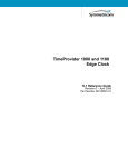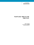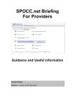
1
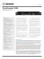
DATA SHEET
TimeProvider 2300
Edge Boundary Clock
Key Features
•Standalone IEEE 1588 Precision Time
Protocol Boundary Clock
•Flexible PTP profiles to support both
frequency and phase synchronization
•ITU-T G.8275.1 Phase/Time
Synchronization using forwardable
address*
•Designed to meet the future ITU-T
G.8275.2 profile for phase synchronization
•Support for 8 to 128 (optional) PTP clients
•Gigabit Ethernet interfaces
•Synchronous Ethernet, input and output
•E1/T1, input or output (option)
•10 MHz, PPS and TOD output
•DC or AC power models
• OCXO or rubidium holdover oscillator
models
• Local and remote CLI, web interface, SNMP traps
•TimePictra Synchronization
Management System support
Key Benefits
•No change out or upgrade of network
hardware
•Mitigates impact of backhaul noise,
packet delay variation and load
asymmetry
•Synchronization protection for high
network availability
•Preserves current MPLS network
engineering
Major Applications
•LTE-FDD, LTE-TDD, LTE-A networks
•Ethernet backhaul networks
This “synchronization overlay” solution is
made possible by features not typically
found in integrated boundary clock designs.
Using Microsemi’s advanced PTP client
software and adaptive timing calculations,
these capabilities include superior clock
recovery algorithms that determine the
best timestamps on which to base the
offset calculation, the ability to mitigate
for timing impairments, faster clock
recovery times, the ability to adapt for load
asymmetry, and the ability to leverage
frequency input from SyncE or E1/T1
signals. The TimeProvider 2300 also offers
the opportunity to upgrade the reference
oscillator to extend the holdover time in the
event input signals are lost.
TimeProvider 2300 supports from 8 to 128
PTP clients, and offers additional output
capabilities that allow it to support legacy
frequency timing applications, including
E1/T1, 10 MHz, pulse per second (PPS)
and time of day (TOD). When deployed in
an end to end network with Microsemi’s
TimeProvider 5000 PTP Grandmaster and
TimePictra® Synchronization Management
System, carriers can also benefit from
superior monitoring information and
management capabilities.
..
..
..
..
..
..
..
..
..
..
..
..
..
..
..
..
..
..
..
..
..
..
..
..
..
..
..
..
..
..
..
..
..
..
..
..
..
..
..
..
..
..
..
..
..
..
..
..
..
..
•Sync solution for the mobile network
edge: 4G/LTE and small cells
The Microsemi® TimeProvider® 2300
is an advanced, standalone IEEE 1588
Precision Time Protocol (PTP) Boundary
Clock optimized to enable deployment
of small cells and meet the stringent
timing and synchronization requirements
of 4G/LTE networks. It is designed for
deployment at selected locations in the
backhaul network following the approach
anticipated in the proposed ITU-T G.8275.2
standard for partial on-path support. This
approach enables timing from a centrally
located grandmaster to be maintained over
currently deployed network equipment—
eliminating the need to upgrade every
element to include a PTP boundary clock
function.
Edge Master Clocks
The continuing evolution of mobile network technologies has driven the need for increased accuracy
and greater availability of timing and synchronization signals. At the same time, backhaul networks
with high packet delay variation present timing “jitter variation” and asymmetry challenges that are
difficult to solve with current solutions. Furthermore, deploying a GNSS receiver at every location is
impractical, particularly in many small cell environments. Together, these issues create the need for
a new overall Synchronization Distribution Architecture for LTE networks.
Edge Master clocks are PTP synchronization equipment designed for deployment in current networks
by locating a grandmaster at or near the edge or by overlaying the network with advanced boundary
clocks at designed locations. They enable mobile network transitions to include small cells, and they
support the stringent LTE-TDD and LTE-A phase and time requirements without overhauling the
current backhaul network. In frequency synchronized networks (LTE-FDD, as well as 2G/3G), Edge
Master equipment can be deployed to eliminate timing issues caused by diverse technologies in the
backhaul network, high packet delay environments, and asymmetry inherent in Carrier Ethernet
networks.
The TimeProvider 2300 is an advanced standalone PTP boundary clock for deployment at planned
locations to support precision time distribution over Ethernet backhaul networks. Also included in the
Edge Master category, Microsemi’s TimeProvider 2700 is a PTP grandmaster deployed at or near the
edge of the network. Together, Edge Master products enable synchronization distribution solutions
that allow the mobile network to continue to evolve without retrofit of existing backhaul equipment
and without changes to current network design and switching/routing policies.
Page 1 of 6
DATA SHEET
TimeProvider 2300
Meeting Stringent Synchronization
Accuracy Requirements
Synchronization accuracy requirements
have gone from relatively routine
frequency specifications (16 ppb on
the network side, 50 ppb for the air
interface) to more stringent time and
phase requirements as tight as ±5 µsec or
even ±1.5 µsec in some of the proposals
under discussion in the standards bodies.
Global Navigation Satellite System (GNSS)
receivers co-deployed or integrated into
the mobile base stations are not always
a feasible solution for either technical
or economic reasons (satellite visibility
and antenna deployment costs for
example). Primary Reference Time Clock
performance, specified by ITU-T G.8272,
meets the accuracy requirements using
a GNSS signal (GPS or GLONASS) as a
reference, and the IEEE 1588 Precision
Time Protocol can deliver the needed
accuracy under the right conditions.
CORE
AGGREGATION
..
..
..
..
..
..
..
..
..
..
..
..
..
..
..
..
..
..
..
..
..
..
..
..
..
..
..
..
..
..
..
..
..
..
..
..
..
..
..
However backhaul networks with many
hops and asymmetric paths between
the grandmaster and the PTP client,
or networks with multiple transport
technologies, or those with high packet
delay variation due to loading or other
issues, cannot be sure to consistently
meet the required specifications.
One solution is to upgrade the backhaul
network for Synchronous Ethernet and
include a PTP boundary clock in every
transport element. This is the approach
in ITU-T G.8275.1 with full timing on
path support from the network. This
solution requires that every network
element between the grandmaster
and the client support Synchronous
Ethernet and include a boundary clock
function—a solution that is not always
feasible due to the high cost to upgrade
a network or because the mobile carrier
employs 3rd party networks for backhaul.
..
..
..
..
..
..
..
..
..
..
..
..
..
..
..
..
..
..
..
..
..
..
..
..
..
..
..
..
..
..
..
..
..
..
..
..
..
..
..
Furthermore, operating at Ethernet
Layer 2, G.8275.1 may obsolete or conflict
with the current MPLS network design
and provisioning policies of the current
backhaul network.
A better solution is to deploy an Edge
Master class of product, using the
approach proposed in G.8275.2. Figure 1
depicts TimeProvider 2300 deployments
at planned locations. This deployment
mitigates or eliminates issues introduced
by the performance of the backhaul, and
therefore, makes unnecessary the need
to upgrade the entire backhaul network to
include boundary clocks in every network
element. Operating over existing networks
at Layer 3, this solution also preserves
current MPLS and other network
provisioning policies and engineering
practices, and it is compatible with and
leverages previous investment in using
the G.8265.1 profile (and pre-standard
profile) for frequency synchronization.
ACCESS
Rb
Time Pictra
T imeP r ovider 2300
TimeProvider 5000
Rb
Macro eNodeB
Rb
TimeProvider 2700
TimeProvider 2300
Small Cell
Aggregation
TimeProvider 5000
..
..
..
..
..
..
..
..
..
..
..
Metro Small Cells
Figure 1: Synchronization overlay using advanced PTP boundary clocks.
TimeProvider 2300 Boundary Clocks are deployed in engineered locations to support accurate time delivery across the backhaul network, or where GNSS
is either not available (urban canyons, subways) or not practical to deploy. The Microsemi TimeProvider 5000 and TimeProvider 2700 Grandmaster clocks
integrate G.8272 compliant Primary Reference Time Clock capability.
Rubidium oscillators, either in the base stations or the PTP Edge Master Clock, extend the holdover period when the primary reference is lost. In the
boundary clock, investment in the high grade oscillator is leveraged across multiple base stations.
The TimePictra Synchronization Management System provides remote management of the synchronization equipment and visibility of all PTP clients.
Page 2 of 6
DATA SHEET
TimeProvider 2300
GNSS (GPS and GLONASS) and
Small Cells
Integrated GNSS receivers are a viable
alternative for timing of macro eNodeB
equipment, though operations would
still be jeopardized by the well publicized
vulnerabilities of GNSS systems, and so
using network distributed synchronization
at least for backup is considered
best practice. Metro or public access
small cells present new challenges
for synchronization. They require tight
timing accuracy, but are often deployed
in locations where adequate GNSS
signal reception is not feasible: indoors,
tunnels and urban canyons for example.
TimeProvider 2300 is designed for
cost effective deployment at small cell
aggregation sites. From this location most
small cell backhaul links can support
distribution of PTP timing to small cell
base stations. Should the small cell
backhaul links themselves include many
hops or high packet delay variation (PDV),
the problem can be solved by deploying
an advanced boundary clock at selected
small cell network nodes.
Protected Synchronization
As tighter synchronization becomes
more essential to the normal operation
of the network (Inter-Cell Interference
Coordination, for example) the negative
impact of loosing synchronization
becomes more significant. Rubidium
oscillators provide a way to protect
synchronization by delivering best-inclass holdover performance (phase timing
of ±1.5 µsec for up to 24 hours). Often
seen as expensive upgrades for individual
macro base stations, rubidium oscillators
in an advanced boundary clock are now
more affordable as their cost is amortized
across an entire cluster of small cells and
co-located macro base stations.
..
..
..
..
..
..
..
..
..
..
..
..
..
..
..
..
..
..
..
..
..
..
..
..
..
..
..
..
..
..
..
..
..
..
..
..
..
..
..
..
..
..
..
..
..
..
..
..
..
..
..
..
..
..
..
..
..
..
..
..
..
..
..
..
..
..
..
..
..
..
..
..
..
..
..
..
..
..
..
..
..
..
..
..
..
..
TimeProvider 2300 Equipment
The TimeProvider 2300 PTP Boundary
Clock provides two gigabit Ethernet
interfaces in a combo port configuration
supporting use of either copper or optical
connections. They are configured as
one PTP input port and one PTP output
port. Synchronous Ethernet is supported
on both ports. Models and options are
available to support 8, 16, 32, 64, or 128
PTP clients; all operating at the full 128
messages per second rate. Client capacity
can be increased in the field with software
license options. The TimeProvider 2300
is available with either an OCXO or
rubidium oscillator; each delivering a
different level of phase and frequency
holdover performance and allowing
operators to better optimize their network
SLAs. The TimeProvider 2300 includes
a programmable 10 MHz or 1 PPS BNC
port and a PPS+TOD RS422 on an RJ45
connection. Models with either dual DC
or a single AC power input are available.
Using passive cooling, the TimeProvider
2300 has no fans.
TimeProvider 2300 Software
License Options
Licensed software options for the
TimeProvider 2300 include:
Greater client capacity: PTP client
capacity in deployed units can be
increased to 16, 32, 64, or 128 clients,
allowing network engineers to design for
capacity they need today and be protected
for increased requirements in the future.
E1/T1 Input/Output: The E1/T1 software
option activates this port for use as either
an input or output. As an input the signal
provides a frequency reference to the
clock function. As an output it can be used
for synchronization of equipment using
this established timing reference.
Default Profile: Enables layer 3 multicast
capabilities for operation in additional
network scenarios.
..
..
..
..
..
..
..
..
..
..
..
..
..
..
..
..
..
..
..
..
..
..
..
..
..
..
..
..
..
..
..
..
..
..
..
..
..
..
..
..
..
..
..
..
..
..
..
..
..
..
..
..
..
..
..
..
..
..
..
..
..
..
..
..
..
..
..
..
..
..
..
..
..
..
..
..
..
..
..
..
..
..
..
..
..
..
Deployment of 4G/LTE networks and
small cells present new technical and
economic issues for network planners
and engineers. A major challenge is to
meet stringent timing requirements over
backhaul paths that were not originally
designed to deliver synchronization at
the level of accuracy needed. Upgrading
the backhaul network or deploying GNSS
receivers at every base station and small
cell is often not possible for technical
or economic reasons. A new type of
synchronization equipment is needed:
the TimeProvider 2300 PTP Boundary
Clock and its companion product, the
TimeProvider 2700 PTP Grandmaster,
enable synchronization architectures
that are more feasible for many network
scenarios.
Page 3 of 6
DATA SHEET
TimeProvider 2300
Specifications
INTERFACES
1 AC power model, IEC 60320 C14 socket
..
..
1 DC power model, dual -48 VDC terminal block
..
..
1 Reset button
..
1 RS232 serial console port, (57,600 bps), DB9
..
..
1 Gigabit Ethernet – Management port
..
- Shielded RJ45, 100/1000 BaseT Ethernet
..
..
2 Gigabit Ethernet – PTP/SyncE input and output combo ports support either:
..
- Shielded RJ45, 100/1000 BaseT Ethernet
..
..
- SFP (optical), 1000 BaseX
..
One combo port is reserved for use as a PTP input (client) and the other combo
..
..
port is reserved for use as a PTP output (master)
..
1 E1 or T1 input or output, software configurable, shielded RJ45 (option)
..
..
- G.703/9, G.823/G.824 sync interface compliance
..
1 Time of Day (TOD) output port, RS422 Data (9600 Baud) with pulse per second
..
(PPS)
..
..
signal, shielded RJ45
..
1 10MHz or 1 PPS output port, BNC (f)
..
..
2 Grounding lugs
..
..
IEEE 1588-2008 PTP OUTPUT
..
• PTP output client capacity: 8 in basic models, options for 16, 32, 64, or 128
..
clients
..
• Up to 128 messages per second per client
..
..
• 1-step and 2-step clock
..
..
• PTP profiles
..
- ITU-T G.8265.1 (layer 3 unicast, IPv4)
..
..
- Telecom-2008 Profile (layer 3 unicast, pre-standard ITU-T G.8265.1, IPv4)
..
- Ethernet-Default Profile (layer 2 multicast, IEEE 1588-2008 Annex F)
..
..
- Default Profile (layer 3 multicast, IEEE 1588-2008) (optional))
..
- ITU-T G.8275.1 Phase/Time Profile using Forwardable address*
..
..
• VLAN (802.1Q, 802.1p). Up to 64 unique VLANs.
..
• Best Master Clock Algorithm (BMCA)
..
..
IEEE 1588-2008 PTP INPUT
..
• Multi-sync function uses both PTP and a frequency input (SyncE or E1/T1). All
..
configurable using reference priority or reference quality.
..
..
• 1-step or 2-step clock
..
..
• Telecom-2008 Profile (layer 3 unicast, pre-standard ITU-T G.8265.1, IPv4)
..
• VLAN (802.1Q, 802.1p)
..
..
HOLDOVER PERFORMANCE
..
..
Oscillator
Phase ±1.5 µsec Phase 5 µsec
Phase 10 µsec Freq 16ppb ..
..
..
OCXO
1 hour
4 hours
12 hours
1 month
..
..
Rubidium
24 hours
3 days
5 days
5 years
..
..
..
Holdover values are approximate and assume operation at constant temperature,
..
no initial frequency or phase offset, and that the units has been powered on for 2
..
weeks and locked to PTP input for three consecutive days.
..
..
SYNCHRONOUS ETHERNET
..
• SyncE can be used as a frequency input or it can be generated as an output
..
(as a master)
..
..
• Conforms to relevant sections of ITU-T G.8261, G.8262, and G.8264 Ethernet
..
Synchronization Message Channel (ESMC)
..
..
NETWORK SUPPORT
..
..
•IPV4
..
•HTTP/HTTPS/SSL
..
..
• ICMP (RFC 792)
..
• DHCP Client (RFC2131)
..
..
• IEEE 1588-2008 Precision Time Protocol
..
• IEEE 802.1Q, 802.1p VLAN filtering/tagging
•DSCP
MECHANICAL
• Size: Height:
1.73 in. (44 mm); 1 RU
Width:
17.24 in. (438 mm)
Depth:
9.30 in. (237 mm)
Depth:
10.07 in. (256 mm) – including
connectors on faceplate
• Rack Mounts: 19 in. and 23 in. rack mount options
• Weight: AC power models: 7.5 lbs (3.4 kg)
DC power models: 8.0 lbs (3.6 kg)
ENVIRONMENTAL
• Operating temperature
- OCXO models: -40°C to +65°C, cold start at -20°C
- Rubidium models: -5°C to +55°C
• Storage temperature: -40°C to +70°C
• Relative humidity: 5% to 95%
POWER
• DC power models: dual power feeds, -38.4 to -72 VDC
• AC power models: 90-264 VAC, 50/60 Hz
• Power consumption
- OCXO model with DC supply: 20 Watts (max), 17 Watts (typical)
- Rubidium model with DC supply: 28 Watts (max), 20 Watts (typical)
- OCXO model with AC supply: 43 Watts (max), 37 Watts (typical)
- Rubidium model with AC supply: 60 Watts (max), 43 Watts (typical)
EMC COMPLIANCE
• FCC Part 15 (Class A)
• AS/NZS CISPR22 (Class A)
• EN55022 (Class A)
• KN55022 (Class A)
• ICES 003 (Class A)
• VCCI (Class A)
• EU 2004/108/EC Electromagnetic Compatibility Directive
• EN 300 386 Telecommunications Network Equipment (EMC)
EMC IMMUNITY
• EN55024 (Class A)
• KN55024 (Class A)
- EN-61000-4-2 ESD
- EN-61000-4-3 Radiated Immunity
- EN-61000-4-4 EFT
- EN-61000-4-5 Surge
- EN-61000-4-6 Low Frequency Common Immunity
- EN-61000-3-2 Power Line Harmonics
- EN-61000-3-3 Voltage Fluctuations / Flicker
- EN-61000-4-11 Voltage Dips and Sags
SAFETY COMPLIANCE
• UL/CSA 60950-1 (2nd edition)
• CAN/CSA-C22.2 No. 60950-1 (2nd edition)
• IEC 60950-1 CB Scheme (2nd edition)
• EN60950-1 (2nd edition)
• CE Mark
ENVIRONMENTAL COMPLIANCE
• EN300-019-2-3, Class T3.2
• ETSI EN 300 019-2-2 (1999) – Transportation, Class T2.3
• ETSI EN 300 019-2-1 (2000) – Storage, Class T1.2
• RoHS (6 of 6)
*: Non-forwardable address, alternate BMCA and select BMCA-related clock attributes not currently supported. Contact Microsemi for details.
Page 4 of 6
DATA SHEET
• Remote software upgrade and rollback
•TimePictra® Management System (purchased separately)
MODELS AND OPTIONS
• TimeProvider 2300 Edge Boundary Clock
- 8 PTP client capacity, upgradable
- Rack mount ears and screws
• Power supply models: AC or DC
• Oscillator models: OCXO or Rubidium
• SW license options
- PTP client capacity upgrade: 16, 32, 64, or 128 clients
- Enable E1/T1 port
- Enable PTP Default Profile (layer3 multicast)
• HW accessories (not included)
- AC power cords
- Ethernet optical SFP transceivers
Ground
AC
Power
(alternative
to DC, not
shown)
-48 VDC Reset
Ethernet 2x GigE
Mgmt. Ports
Dual Button
Copper or
Feeds
Craft
Optical
Port
E1/T1
TOD
Ports
10Mhz or
1PPS
Port
Ground
**: When following deployment guidelines as specified in the user manual.
Delay can vary as PTP packets are processed, buffered and queued
along with the payload traffic through the network switches and
routers, and it tends to be correlated to network load which can be
highly asymmetric in nature. As the amount of traffic in the network
increases, the delay variation is also likely to increase.
Time accuracy is affected by both the magnitude of this variation and
how effective the client is at removing this noise. The TimeProvider
2300 incorporates Microsemi’s advanced PTP client technology and
a high quality reference oscillator. Advanced algorithms effectively
filter this noise, allowing the timing signal at the base station to
remain within specification.
Frequency, Phase and Time Synchronization
Frequency Synchronization
T A=1/fA
A
Leading edge of the
pulses are at same
pace, but not at the
identical moment.
t
T B =1/fB
B
t
f A=fB
Phase Synchronization
T A=1/fA
A
t
T B =1/fB
B
Time Synchronization
A
T A=1/fA
t
T B =1/fB
Leading edge of the
pulses are at the
identical moment
and identical time.
t
01
:0
0:
10
00
0:
:0
f A=fB
01
B
Leading edge of the
pulses are at the
identical moment.
t
f A=fB
10
• Ability to disable management interfaces
0:
• Multi level user access
The problem is Packet Delay Variation (PDV) which represents the
change in latency from packet to packet. Packet delay itself has no
effect on the accuracy of the clock: constant delay would allow an
accurate time offset calculation by the PTP client. Variable delay,
however, induces noise in the PTP client’s perception of the time at
the master which can result in variation in time calculations based
on the timestamps in the PTP packets.
:0
• Web interface (HTTP/HTTPS)
01
• CLI, local (serial) and remote (telnet/SSH)
00
•SYSLOG
Timing and synchronization, fundamental in all mobile networks, is
even more critical as small cells are added and networks evolve to
LTE-TDD and LTE-A technologies. Backhaul network performance
can dramatically impact PTP timing accuracy, and thereby the mobile
network itself—affecting service quality and customer satisfaction.
0:
NETWORK EQUIPMENT BUILDING SYSTEM
• NEBS Level 3**, GR-1089
MANAGEMENT AND SECURITY
• SNMP v2c, v3 traps
Packet Delay Variation (PDV) and Asymmetry
:0
Specifications
01
TimeProvider 2300
..
..
..
..
..
..
..
..
..
..
..
..
..
..
..
..
..
..
..
..
..
..
..
..
..
..
..
..
..
..
..
..
..
..
..
..
..
..
..
..
..
..
..
..
..
..
..
..
..
..
..
..
..
..
..
..
..
..
..
..
..
..
..
..
..
..
..
..
..
..
..
..
..
..
..
..
..
..
..
..
..
..
..
.
Page 5 of 6
DATA SHEET
Microsemi Corporate Headquarters
One Enterprise, Aliso Viejo,
CA 92656 USA
Microsemi Corporation (Nasdaq: MSCC) offers a comprehensive portfolio of semiconductor and
system solutions for communications, defense & security, aerospace and industrial markets. Products
include high-performance and radiation-hardened analog mixed-signal integrated circuits, FPGAs,
SoCs and ASICs; power management products; timing and synchronization devices and precise
time solutions, setting the world’s standard for time; voice processing devices; RF solutions; discrete
components; security technologies and scalable anti-tamper products; Power-over-Ethernet ICs and
midspans; as well as custom design capabilities and services. Microsemi is headquartered in Aliso
Viejo, Calif., and has approximately 3,400 employees globally. Learn more at www.microsemi.com.
Microsemi makes no warranty, representation, or guarantee regarding the information contained herein or
the suitability of its products and services for any particular purpose, nor does Microsemi assume any liability whatsoever arising out of the application or use of any product or circuit. The products sold hereunder and any other products sold by Microsemi have been subject to limited testing and should not be
Within the USA: +1 (800) 713-4113
Outside the USA: +1 (949) 380-6100
used in conjunction with mission-critical equipment or applications. Any performance specifications are
Sales: +1 (949) 380-6136
believed to be reliable but are not verified, and Buyer must conduct and complete all performance and
Fax: +1 (949) 215-4996
other testing of the products, alone and together with, or installed in, any end-products. Buyer shall not
rely on any data and performance specifications or parameters provided by Microsemi. It is the Buyer's
E-mail: [email protected]
responsibility to independently determine suitability of any products and to test and verify the same. The
information provided by Microsemi hereunder is provided "as is, where is" and with all faults, and the
© 2015 Microsemi Corporation. All
entire risk associated with such information is entirely with the Buyer. Microsemi does not grant, exrights reserved. Microsemi and the
plicitly or implicitly, to any party any patent rights, licenses, or any other IP rights, whether with reMicrosemi logo are trademarks of
Microsemi Corporation. All other
gard to such information itself or anything described by such information. Information providtrademarks and service marks are the
ed in this document is proprietary to Microsemi, and Microsemi reserves the right to make any
property of their respective owners.
changes to the information in this document or to any products and services at any time without notice.
DS/TimeProvider2300/051115
900-00512-000F