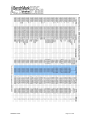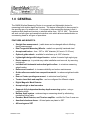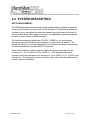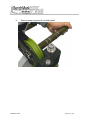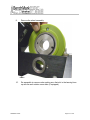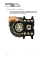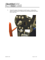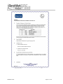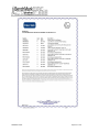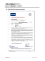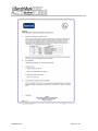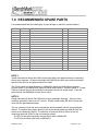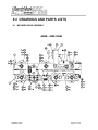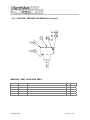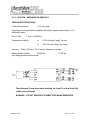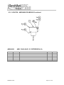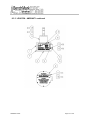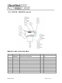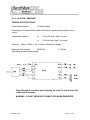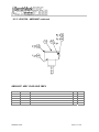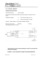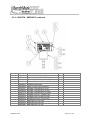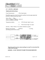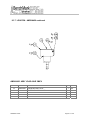
1
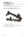
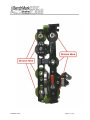
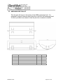
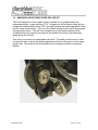
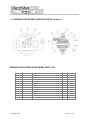
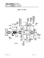
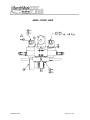
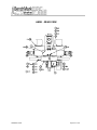
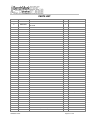
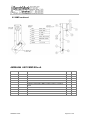
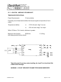
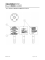
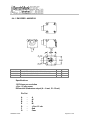
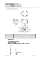
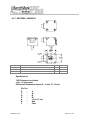
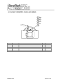
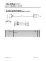
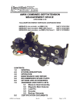
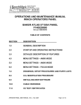
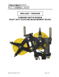
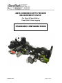
AM5K COMBINED DEPTH/TENSION MEASUREMENT DEVICE For Open & Cased Hole or Cased Hole E-Line Logging STANDARD CONFIGURATIONS AM5KSTD11MAY Page 1 of 100 AM5KSTD11MAY Page 2 of 100 AM5KSTD11MAY Page 3 of 100 AM5KSTD11MAY Page 4 of 100 CONTENTS 1.0 GENERAL 2.0 SYSTEM DESCRIPTION 3.0 OPERATION 4.0 MAINTENANCE AND REPAIR 5.0 OPTIONS AND ACCESSORIES 6.0 CERTIFICATION DOCUMENTS 7.0 RECOMMENDED SPARE PARTS 8.0 DRAWINGS AND PARTS LISTS AM5KSTD11MAY 8.1 MEASURING HEAD ASSEMBLY 8.2 MAGNETIC MARK DETECTOR 8.3 LOAD PIN 8.4 ENCODER 8.5 BACKUP ODOMETER Page 5 of 100 Manual Revision Log Revision R - Jun 2010 Page 12 Pages 24-27 Pages 43-48 AM5KSTD11MAY Added contact information for customer support Added Options and Accessories section Added new ATEX Zone 2 Certificates Updated parts lists and numbers Page 6 of 100 1.0 GENERAL The AM5K Wireline Measuring Device is a compact and lightweight device for measuring both wireline depth and tension. The device is designed to be mounted to the spooling arm of a wireline unit. It is unique to other measuring devices in that it measures both depth and tension on wireline cables from .190” to .494”. This device will work on both open and cased hole wireline units which allows standardization on a measuring head for all types of operations. FEATURES AND BENEFITS: Straight-line measurement - (cable sizes can be changed without affecting depth measurement) Dual Tangential Measuring Wheels - made from specially hardened steel Accepts cable sizes - from .190” to .494” diameter (4.8 mm to 12.55 mm) Optional guide wheels - available for wirelines up to .650” diameter Lightweight design with integral tension - makes for easier high angle rigup Device opens up - to provide easy cable installation and removal, by removing a single pin Includes both horizontal and vertical guide rollers - to minimize measuring wheel loading Rollers are oversized - to increase reliability and reduce maintenance Guide rollers are made from composite material - to reduce weight and cable wear Rear or Center spooling arm mount - to minimize head “jerking” Tension Load Axle and amplifier - can be configured for different outputs. Digital Magnetic Mark Detector Accepts single or dual encoders Supports fully independent backup depth measuring system - using a magnetic pickup Backup depth system - reduces drag on measuring wheel by eliminating mechanical drive cable Encoder, Mark Detector, and Tension amplifier - certified for Zone II area use Anodized aluminum frame - All steel parts are plated or SST All bearings are SST AM5KSTD11MAY Page 7 of 100 2.0 SYSTEM DESCRIPTION DEPTH MEASUREMENT: The AM5K Measuring Head uses dual spring-loaded measuring wheels to measure the amount of wireline moving to and from the borehole. The measuring wheels are coupled to one or two optical encoders that transmit electrical signals via a cable to the hoistman’s panel and/or logging computer. An independently powered magnetic encoder is used for back up depth indication. The hardened measuring wheels are 2.0000 ft. (.609600 m) in circumference. Springs are used to hold the measuring wheels in contact with the wireline. The springs are sized to provide the appropriate friction between the wheels and wireline. The frame members are anodized 6061-T6 aluminum. Under ideal conditions, without magnetic marks, the measuring heads have an accuracy of +/- 3 m in 3000 m (10 ft in 10,000 ft.). With magnetic marks and accurate line stretch calculations, an accuracy of .3 m in 3000 m (1 ft in 10,000 ft) can be achieved. The Hoistman's panel is required to fully utilize the mark detection and stretch correction algorithms. AM5KSTD11MAY Page 8 of 100 TENSION MEASUREMENT: The AM5K uses an electronic load axle to measure line tension. Three wheels are used to create a force on the load axle. To generate this force the wheel mounted on the load axle is offset from the other two slightly. This offset creates a slight bend in the cable. As wireline tension increases the small offset creates a corresponding bending force on the strain-gauged load axle. An electronic signal is transmitted via cable to the hoistman’s panel and/or logging computer representing wireline tension. A calibrate resistor is included in the load pin to send out a signal to calibrate the computer system. GENERAL SPECIFICATIONS: WEIGHT: 58 lbs 26.3 kg LENGTH: 26.5” 673 mm HEIGHT: 10.8” 274 mm WIDTH: 15.3” 389 mm MAXIMUM TENSION: 20,000 lbs 9072 kg MEASURING WHEEL SIZE: 24.000” 609.60 mm CABLE SIZES: .190” to .494” 4.8 mm to 12.55mm CABLE BEND OVER TENSION WHEEL: 2.5 – 7.5 degrees (depends on cable) Minimal or no affects on magnetic marks AM5KSTD11MAY Page 9 of 100 3.0 OPERATION 3.1 SPOOLING ARM INSTALLATION – OVERHEAD SPOOLING ARM Take Adequate Precautions when installing the Measuring Head to Avoid the Risk of Mechanical Damage Install the measuring head on to the spooling arm by using the top adapter mount assembly to mount to an overhead spooling arm. The mount is designed to mount with a standard U-joint yoke. AM5KSTD11MAY Page 10 of 100 3.1 SPOOLING ARM INSTALLATION continued MOUNTING YOKE AM5KSTD11MAY Page 11 of 100 Make sure that the head can freely sit on the wireline. If the mounting arrangement will not let the head travel up and down freely and if the cable puts a upward or downward force on the measuring head, this force will cause an offset to the tension measurement which will result in an incorrect tension reading. AM5KSTD11MAY Page 12 of 100 3.2 CABLE INSTALLATION To install cable, first open the wheels by shifting the red release handles. Next, remove the push pin, and hinge the head open. Lifting up on the wireline cable makes it easier to remove the push pin. The cable can now be inserted or removed. Close the red release handles to tighten the wheels against the wireline. Swing the head closed and reinsert the pin. AM5KSTD11MAY Page 13 of 100 3.3 CABLE REMOVAL UNDER LOAD 3.3.1 If under load, the load will need to be removed from the device prior to removing the retaining pin. A “C-clamp" or a nylon "ratchet strap" can be used to remove the load. 3.3.2 Install a C-Clamp across the top and bottom frames as shown in the drawing below. The ratchet strap can be installed in a similar way. 3.3.3 Tighten the C Clamp until the load is removed from the retaining pin. Remove the retaining pin then loosen and remove the C Clamp. AM5KSTD11MAY Page 14 of 100 3.4 CHANGING CONFIGURATION BETWEEN OPEN HOLE AND CASED HOLE A measuring head configured for open hole will typically contain a magnetic mark detector and a 2nd encoder. Cased hole operations rarely require a magnetic mark detector and typically use only one encoder. If the head is configured for open hole, no changes are required to run it on a cased hole unit. You may elect to remove the magnetic mark detector if you have no plans to use the head on an open hole unit any time in the near future. The cased hole head can be configured with a different wear plate. The cased hole wear plate is thicker and stepped on one end to the keep the line from riding near the top of the wheels. This can occur when going in the hole with a small cable (7/32") with a very light load. The open hole wear plate is flat. Both plates are made from hardened tool steel. The wear plate is mounted on the upper frame above the measure wheels. Part number for the open hole wear plate is: AM5KM034 Part number for the cased hole wear plate is: AM5KM074 3.4.1 To remove the magnetic mark detector, refer to item 12 on the parts list. Remove the four screws holding the detector in place then remove the detector. To install a magnetic mark detector, reverse this procedure. 3.4.2 To remove an encoder, remove the four screws securing the encoder adapter to the head. Remove the encoder and adapter. Remove the coupling from the measuring wheel shaft. AM5KSTD11MAY Page 15 of 100 3.5 INSTALLING THE DEEP GROOVED TENSION WHEEL 3.5.1 A deep grooved "High Tension" wheel is available for use when line tension greater than 12,000 lbs is commonly encountered. This wheel is grooved to better support the wireline at high tensions. The groove also reduces the radius of the wheel which lowers the bend angle of the wireline. This wheel is only for use with 15/32” or larger cables and cannot be used with smaller cable sizes. The normal shallow grooved wheel can be used at high loads for short pull durations but should not be used when loads exceed 12,000 lbs for an extended period of time. DEEP GROOVED HIGH TENSION WHEEL STANDARD SHALLOW GROOVED TENSION WHEEL AM5KSTD11MAY Page 16 of 100 3.5.2 To install the deep grooved tension wheel, replace the standard shallow grooved tension wheel with the deep grooved tension wheel. The load pin does not need to be changed. To account for the decreased bend angle of the cable, the Load Cell Angle value will need to be changed when using this wheel. Ensure that the slot in the bushing of the tension wheel is aligned with the roll pin on the side of the frame. The roll pin is only installed on one side of the frame and it needs to be inserted in the slot. Also ensure that the grease hole in the tension wheel is installed on the opposite side as the load pin amplifier. AM5KSTD11MAY Page 17 of 100 3.6 SYSTEM OPERATION 3.6.1 Determine cable size to be used – .490" to .190”. Since the wireline cable actually bends over the tension wheel, the bend radius of the wireline cable will affect the tension measurement. 3.6.2 Enter tension calibrate factor. These corrections are automatically made in the Benchmark Hoistman's panel by selecting the proper cable size from the menu. If a different panel is used, enter the tension factor at this time. Value for shallow grooved tension wheel with standard load pin VALUES .9 1 1.1 1.2 1.4 1.5 1.8 CABLE SIZE .484 .472 7/16” 3/8” 5/16” 9/32” 7/32” Value for deep grooved tension wheel with standard load pin VALUES 2.15 2.30 2.40 CABLE SIZE .490 .484 .472 3.6.3 Install line in measuring head (refer to section 3.2). 3.6.4 Make sure line is lying slack and head is free to move. Press the Ten Zero Cal button and tension value should read 0. 3.6.5 Press the Ten Cal button and tension should read the value indicated in paragraph 3.6.2. 3.6.6 At this point, the system is ready to log. Watch for visual indications of problems such as excessive vibration, wheel or roller slippage or lockups that signify bearing or shaft failures, or cable tracking problems. AM5KSTD11MAY Page 18 of 100 4.0 MAINTENANCE AND REPAIR 4.1 OBTAINING TECHNICAL ASSISTANCE Call BenchMark Wireline Products Inc. at +1 281 346 4300 Or contact by email [email protected] Or fax in request at +1 281 346 4301 Information in the form of user manuals and instructional videos are also available on our website www.benchmarkwireline.com Parts can be ordered by email, phone, or fax Equipment can be returned for repair and maintenance. Please notify us by Phone, email, or fax before sending any equipment. To return equipment to BenchMark, ship it to: BenchMark Wireline Products 36220 FM 1093 Simonton, Texas 77476 U.S.A. AM5KSTD11MAY Page 19 of 100 4.2 PRE-JOB CHECK Each time the system is used perform the following steps: Verify that the AM5K is properly and securely attached to the spooling arm. Several different mounting kits are available for different types of spooling arms. Verify that the depth measuring wheels are clean and that no groove has been worn into the measuring wheel surface. Check the measuring and guide wheels for looseness, play, out-of-roundness, worn or rough sounding bearings, or other mechanical conditions that could affect measurement accuracy. Ensure that the wheel bearings inner race is not spinning on the shaft and that the shaft is not spinning in the bushings. Verify that all fasteners are tight and that the ball lock pushpin is secure. Verify that the encoder, electronic load pin, and backup counter cable are installed and properly routed. Verify that the depth system is working by turning the wheel and observing the hoistman’s panel and backup display unit to indicate cable movement. The hoistman's panel and backup display should measure 2' for each rotation of the wheel. If more than one encoder is installed check both encoders by turning each wheel and verifying that the hoistman's panel will read 2' for each rotation of either wheel. AM5KSTD11MAY Page 20 of 100 4.3 POST-JOB MAINTENANCE At the completion of each job, thoroughly clean and dry the device as soon as possible. This avoids problems caused from borehole residues transferred from the wireline onto the measuring device. Borehole residues should be washed from the device with a cleaning solvent such as Varsol or an equivalent type. Rinse the device with water, dry, and wipe down with an oily rag. Do not pressure wash AM5KSTD11MAY Page 21 of 100 4.4 MONTHLY MAINTENANCE Visually inspect the interiors of the electrical connectors for the encoders and electronic load axle for dirt and evidence of insulation breakdown. Clean or replace as necessary. Install dust caps on the connectors if the cables are removed. Manually rotate each wheel by hand to verify its condition. Inspect the depth measuring wheels for signs of abnormal wear, diameter changes, or shaft/bearing play that can affect measurement accuracy. The wheel should be replaced if it is grooved more than .005". The wheel should be 7.639 / 7.640" (194 mm) in diameter with a 24" circumference (609.6 mm). Inspect the tension wheel for signs of abnormal wear, diameter changes, or shaft and bearing play that could affect tension measurement accuracy. The shallow groove tension wheel (item 33 in section 6.1 of this manual) should be 5" in diameter at the bottom of the groove. It should be replaced if it is worn more than .010". The deep grooved tension wheel (item 33 in section 6.1 of this manual) should be 4.375" in diameter at the bottom of groove. It should be replaced if it is worn more than .010". Inspect the two grooved guide wheels on either side of the tension wheel (items 34 in section 6.1 of this manual). They should be 4" (101.6 mm) in diameter (bottom of groove). They should be replaced if they are worn more than .010". NOTE: If the tension wheels or guide wheels mentioned above are worn more than .010” then the tension reading will be less than the actual line tension. The amount of error is relative to the amount of wear. Grease all the wheels and bearings that are fitted with a flush mount grease fitting (see following diagram). Use a water-proof, marine grade grease. An inverted grease nozzle (p/n AM5KP130) is supplied with each head. This nozzle will fit any standard grease gun. AM5KSTD11MAY Page 22 of 100 AM5KSTD11MAY Page 23 of 100 4.5 ASSEMBLY / DISASSEMBLY PROCEDURES WARNING – DO NOT SEPARATE CONNECTORS WHEN ENERGIZED 4.5.1 MEASURING WHEEL, SHAFT, AND BEARING REMOVAL Either measuring wheel can be removed from the measuring head. First shift the red release handle to move the wheel away from the frame. Next remove the encoder with its adapter. On the later model heads, the wheels are keyed onto the shaft and can be removed simply by removing the screw holding the wheel to the shaft. On earlier model heads, the wheels are pressed on to the shaft. The lower snap ring between the wheel and the bearing must first be removed. Pull the wheel and shaft from the mount. Reassemble in the opposite order. The bearing should also be replaced at this time. 4.5.2 ELECTRONIC LOAD PIN REMOVAL The electronic load pin is held in place by one retaining ring on the outer end of its shaft. Remove the retaining ring by using a small screw driver to lift one end of the ring out of the groove then “walk” the ring off of the pin. The load pin can then be removed from the mounting frame. 4.5.3 BACKUP DEPTH MAGNETIC PICKUP REMOVAL AND INSTALLATION The backup depth magnetic pickup is mounted to the encoder adapter. It is held in place by four screws. Remove the screws and the pickup can then be removed. The pickup must be properly oriented to work correctly. The slot should be oriented to the top. The top side is the encoder side. Ensure that an o-ring is inserted between the plastic housing and the mount. An additional o-ring is used between the connector and the housing to keep moisture out. If the backup display is counting backward (i.e. counting negative when going down hole), simply rotate the pickup 180 degrees to change the direction. AM5KSTD11MAY Page 24 of 100 4.5.4 ENCODER COUPLING INSTALLATION To install the encoder coupling, first remove the plug in the encoder adapter. Install one of the metal parts of the three piece coupling (item 36) to the wheel shaft and tighten it using a hex wrench. Next, install the center plastic piece of the coupling onto the wheel shaft coupling. Place the other metal coupling on the encoder shaft and set the encoder on the mount. Snug up the encoder coupling then remove the encoder and tighten the coupling. Reinstall the encoder with o-rings (item 98) and tighten it to the encoder mount (item 6). Next tighten the plug. See Parts List in Section 8.1 AM5KSTD11MAY Page 25 of 100 4.5.5 ENCODER MOUNT AND TOP GUIDE WHEEL REMOVAL Follow these steps to remove the encoder mounts. 1. AM5KSTD11MAY Using a pair of vice grips, grab the end of the pin and pull on it. Page 26 of 100 2. AM5KSTD11MAY Use a screw driver to capture the end of the spring. Page 27 of 100 3. AM5KSTD11MAY The end cap and the pin can now be removed. Page 28 of 100 4 AM5KSTD11MAY Use a hook to pull the spring out far enough to remove the screwdriver (Careful not to bend the spring). Page 29 of 100 5. Remove the floating encoder assembly. 6. Repeat for the other side. AM5KSTD11MAY Page 30 of 100 7. AM5KSTD11MAY Remove anti-rotation screw (if equipped). Page 31 of 100 8. AM5KSTD11MAY Remove snap ring and pull out sliding shaft. Page 32 of 100 9. Remove the wheel assembly. 10. Re-assemble in reverse order making sure that slot in the bearing lines up with the anti rotation screw hole (if equipped). AM5KSTD11MAY Page 33 of 100 4.5.6 INSTALLING THE LOAD AXLE WHEEL 1. AM5KSTD11MAY Insert the tension wheel into the frame. Make sure the slotted hole in the tension wheel bushing is on the same side as the roll pin hole in the frame and the grease hole is on the opposite side. Page 34 of 100 2. Use a bolt in place of the load pin to hold it in place. Install an Allen wrench or other long tool to align the hole in the bearing with the slotted hole in the frame. AM5KSTD11MAY Page 35 of 100 3. Insert a 3/16” x 1/2” long roll pin into the hole. Do not use a longer roll pin as it will bind the wheel. AM5KSTD11MAY Page 36 of 100 4. Drive the roll pin flush. Make sure that the wheel can freely slide up and down in the frame. AM5KSTD11MAY Page 37 of 100 5. Remove the bolt and install the load pin. Align the notch in the load pin with the flat side on the frame. AM5KSTD11MAY Page 38 of 100 AFTER ASSEMBLY IS COMPLETE THE LOAD PIN SHOULD BE CONFIGURED AS SHOWN BELOW AM5KSTD11MAY Page 39 of 100 5.0 OPTIONS AND ACCESSORIES 5.1 SHIPPING CASE AM5KM197 This case is designed to help easily transport the measuring head. CUSTOM FOAM LINED FOR AM5K RETRACTABLE HANDLE ROLLER WHEELS OUTSIDE DIMENSIONS: 31.5L X 22.88W X 18.88 AM5KSTD11MAY Page 40 of 100 5.1 SHIPPING CASE continued - AM5KM197 AM5K SHIPPING CASE AM5KSTD11MAY Page 41 of 100 5.2 AM5KA090 DRIP PAN KIT This drip pan will mount to the bottom of the AM5K measuring head. It is designed to capture fluids and debris that drip or fall from the measuring head. A hose is provided as a means to drain the pan into an external container. P/N AM5KM090 AM5KM092 AM5KP205 AM5KP209 AM5KP208 AM5KP207 AM5KSTD11MAY DESCRIPTION PAN DRIP ALUMINUM AM5K PIN CLEVIS 13/16 X 2-3/4 SST PIN HAIR 0.125 X 5/8-7/8 SST TEE 3/4 MALE PUSH-ON NYLON CLAMP HOSE 0.56-1.06 SST TBG PVC .75ID X 1.00OD CLEAR QTY UNIT 1 2 4 1 5 12 EA EA EA EA EA EA Page 42 of 100 5.3 AM5KA239 ADJUSTABLE GUIDE ROLLER KIT This kit is designed to force smaller sizes of wireline to run straight across the measuring wheels. Large wirelines (7/16” or larger) are stiff enough so they will run straight but smaller lines such as 7/32” can walk up/down the measuring wheel if they are not under much tension. This can occur when running into the well with pressure through grease tubes. This will cause a depth error (less depth measured then actual) because any vertical movement of the wireline will not turn the measuring wheel as far as it should. This roller is mounted on an adjustable cam shaft. The shaft can be turned to raise or lower the roller to press the wireline against the bottom of the groove in the upper guide roller. This assures that the wireline will run straight across the measuring wheels. AM5KSTD11MAY Page 43 of 100 5.3 AM5KA239 ADJUSTABLE GUIDE ROLLER KIT continued AM5KA239 ADJUSTABLE GUIDE WHEEL PARTS LIST ITEM P/N 1 2 3 4 5 6 7 8 9 10 11 12 AM5KM231 AM5KM232 AM5KA144 AM5KP234 AM5KP235 AM5KM146 AM5KM147 AM5KM148 AM5KP236 AM5KP181 AMS1P058 C276P513 AM5KSTD11MAY DESCRIPTION SHAFT KEYED 3/4 ADJ RLR SST BOLT MOD SHOULDER 5/16 X 1 SST ASSY WHEEL GUIDE 4.266 SST SPRING COMP 7/8 OAL 0.42 OD KEY 3/16 SQUARE SST BUSHING INDEXED KEYED 30MM BUSHING 30MM KEYED 3/4 SHAFT COLLAR LATCH ADJ ROLLER SST BEARING BRZ .314 ID X .378 OD SCREW 3/8-16 X 3/4 BUTTON HD WASHER 3/8 LOCK SS WASHER 3/8 FLAT SST QTY 1 1 1 1 2 1 1 1 1 2 2 2 UNIT EA EA EA EA EA EA EA EA EA EA EA EA Page 44 of 100 5.4 550 WHEELS AM5KK550 This kit includes guide wheels and tension wheel that are grooved to fit wirelines from .500” up to .550” diameter. The kit includes 6 steel guide wheels. It replaces the two steel guide wheels and four plastic guide wheels on the standard head. A new tension wheel is also included. The tension “K” factor is different with this wheel. P/N AM5KA091 AM5KA095 AM5KSTD11MAY DESCRIPTION ASSY WHEEL TENSN FIXD 35MM BRG ASSY WHEEL TENS 0.550 LOAD AXL QTY UNIT 6 1 EA EA Page 45 of 100 5.5 650 WHEELS AM5KK650 This kit includes guide wheels and tension wheel that are grooved to fit wirelines from .550” up to .650” diameter. The kit includes 6 steel guide wheels. It replaces the two steel guide wheels and four plastic guide wheels on the standard head. A new tension wheel is also included. The tension “K” factor is different with this wheel. P/N AM5KA092 AM5KA096 AM5KSTD11MAY DESCRIPTION ASSY WHEEL TENSN FIXD 35MM BRG ASSY WHEEL TENS 0.650 LOAD AXL QTY UNIT 6 1 EA EA Page 46 of 100 6.0 CERTIFICATION DOCUMENTATION 6.1 MEASURING HEAD ATEX Conformity Certificate AM5KSTD11MAY Page 47 of 100 6.2 MEASURING HEAD ATEX Conformity Certificate – Sheet 1 AM5KSTD11MAY Page 48 of 100 MEASURING HEAD ATEX Conformity Certificate – Sheet 2 AM5KSTD11MAY Page 49 of 100 6.3 ENCODER ATEX Conformity Certificates AM5KSTD11MAY Page 50 of 100 AM5KSTD11MAY Page 51 of 100 AM5KSTD11MAY Page 52 of 100 6.4 LOAD PIN ATEX Conformity Certificates AM5KSTD11MAY Page 53 of 100 AM5KSTD11MAY Page 54 of 100 AM5KSTD11MAY Page 55 of 100 6.5 MARK DETECTOR ATEX Conformity Certificates AM5KSTD11MAY Page 56 of 100 AM5KSTD11MAY Page 57 of 100 7.0 RECOMMENDED SPARE PARTS It is recommended that the following list of parts be kept on hand for remote locations. ITEM 10 12 13 14 22 31 33 33 34 35 36 51 54 55 56 58 59 101 P/N AM5KA066 AM5KA058 AM5KM001 AM5KA137 AM5KA063 AM5KA073 AM5KA164 AM5KA065 AM5KM073 AMS1P009 AM5KM157 AM5KP088 AM3KP204 AM5KM134 AM5KP229 AM5KP130 DESCRIPTION ASSY LOAD AXLE ASSY MAG MARK DETECTOR EEx nA ENCODER ASSY BACKUP MAGNETIC EEx Na WHEEL MEASURING 2FT 5 SPOKE ASSY WHEEL GUIDE PLAS 35MM BRG ASSY WHEEL TENSN SHALLOW GROOVE ASSY WHEEL TENSN DEEP GROOVE ASSY WHEEL TENSN FIXD 35MM BRG ASSY ROLLER SPOOLNG 2.75" PLAS COUPLING MOD ENCDR 0.250/0.375 RETAINING PIN (T HANDLE) BEARING BALL 35MM ID MOD BEARING LINEAR 30MMID X 40MMOD BEARING BALL 20MM FAFNIR 204PP BEARING BALL 40MM ID MOD CLAMP TOGGLE PUSH/PULL SST NOZZLE GREASE FITTNG FLUSH QTY 1 1 1 1 2 4 1 1 2 4 2 1 6 8 4 1 1 1 REF SEE CHART SEE CHART OPTION (HI TENSION) NOTE 1: Heads manufactured before Nov 2002 required the shaft to be replaced when the measuring wheels were replaced. All later model heads (SN 5K0229) and after come with keyed shafts that allow the wheel to be replaced without the shaft. The P/N for wheel and shaft assembly is AM5KA025 (wheel and shaft without magnets Encoder Wheel 1) and AM5KA060 (wheel and shaft with magnets - Encoder Wheel 2). If these P/Ns are ordered, they will automatically be supplied with the new keyed shafts. From that point forward, the AM5KM001 wheels can be used. NOTE 2: Heads manufactured before Feb 2004 did not have greaseable bearings. We have since created a greaseable version for all 7 wheels. All later model heads (SN 5K0412) and after come with the greaseable bearings. The top 4 wheels on both old and new heads are interchangeable with the new greaseable wheels. The bottom three plastic wheels in the old measuring heads are different then the wheels in new Measuring heads. The diameter of the wheel shaft is 20mm for the old measuring head and 35mm for the new measuring head. - The P/N for this wheel assembly with the 20mm shaft is AM5KA139 - The P/N for the 20mm shaft only is AM5KM012 AM5KSTD11MAY Page 58 of 100 8.0 DRAWINGS AND PARTS LISTS 8.1 MEASURE HEAD ASSEMBLY AM5K - SIDE VIEW AM5KSTD11MAY Page 59 of 100 AM5K - TOP VIEW AM5KSTD11MAY Page 60 of 100 AM5K - FRONT VIEW AM5KSTD11MAY Page 61 of 100 AM5K - REAR VIEW AM5KSTD11MAY Page 62 of 100 PARTS LIST ITEM P/N 1 AM5KA131 2 AM5KA332 3 4 5 6 6 7 8 9 10 11 12 13 14 15 16 17 18 19 20 21 22 23 24 25 25 26 27 28 29 30 31 33 33 34 35 36 37 38 42 43 51 52 AM5KA052-1 AM5KA052-2 AM5KA053 AM5KM057 AM5KM058 AM5KM020 AM5KA057 AM5KM026 AM5KA040 AM5KA066 AM5KA058 AM5KM024 AM5KM011 AM5KA059 AM5KM023 AM5KM013 AM5KP023 AM5KP002 AM5KM001 AM5KM141 AM5KM034 AM5KM049 AM5KM074 AM3KM134 AM5KM159 AM5KM084 AM5KM010 AM5KM060 AM5KA137 AM5KA063 AM5KA073 AM5KA164 AM5KA065 AM5KM073 AM5KP124 AM5KP125 AM5KM138 AM5KM040 AMS1P009 AMS1P072 AM5KSTD11MAY DESCRIPTION ASSY FRAME BACKBONE UPPER W/BUSHINGS ASSY LOWER FRAME W/BUSHINGS AND WEAR BLOCKS ASSY MOUNT FLTNG ENCDR WHL W/ ASSY MOUNT FLTNG ENCDR WHL W/0 ASSY BLOCK PIVOT HORIZ/VERT ADAPTER ENCODER H37C/H25D COVER ENCODER ADAPTER ENDCAP FLOATING ENCODER MOUNT ASSY MOUNT SPOOLNG ROLLR FRNT MOUNT SPOOLING ROLLER REAR ASSY LOAD AXLE ASSY MOUNT CENTER YOKE 5 WHEEL ASSY MAG MARK DETECTOR EEx Na ENCODER ASSY BACKUP MAGNETIC EEx Na SHAFT PIVOT VERTICAL 20MM SST SHAFT TENSION ROLLER 30MM SST ASSY SHAFT ENCODER SLIDE 30MM SHAFT PIVOT HORIZONTAL 1/2 SST SHAFT SPOOLING ROLLER 20MM BOLT SHOULDER 3/4 X 3 SST SPRING EXT 4" OAL 47/64 DIA SST WHEEL MEASURING 2FT 5 SPOKE ANCHOR SPRING 1/2" FLOATING PLATE WEAR 1/16 X 1.5 X 3.5 BLOCK WEAR 1.50 X 1.50 X 0.56 STL BLOCK WEAR UPPER TOOL STL CH BLOCK WEAR 0.75 X 2.50 TOOLSTL BLOCK GUIDE TENSION WHEEL PLAS SCREW ANTI-ROTATION TENS WHEEL SHAFT WHEEL CANTILEVERED 5 WHL SHAFT WHEEL CANTLVRD MAG 5 WHL ASSY WHEEL GUIDE PLAS 35MM BRG ASSY WHEEL TENSN SHALLOW GRV ASSY WHEEL TENSN DEEP GRV ASSY WHEEL TENSN FIXD 35MM BRG ASSY ROLLER SPOOLNG 2.75" PLAS COUPLING MOD ENCDR 0.250/0.375 PIN COILED SPRING 1/4 X 1-1/8 PIN COILED SPRING 3/16 X 1/2 YOKE PIVOT CENTER MOUNT SST PUSHROD TOGGLE CLAMP PLASTIC RETAINING PIN (T HANDLE) PLUG 3/8 NPT SS QTY REF 1 1 1 1 1 2 1 4 1 1 1 1 1 1 1 1 5 2 1 3 1 4 2 4 1 2 1 2 2 6 1 1 4 1 1 2 4 2 2 1 1 2 1 2 OPTION OPTION OPTION SEE CHART OPTION SEE CHART LARGE LINES SMALL LINES ONLY OPTION OPTION OPTION (HI TENSION) OPTION ENCODER SLIDE TENSION WHEEL PIN Page 63 of 100 53 54 55 56 58 59 60 61 62 63 64 65 66 67 68 69 70 71 72 73 74 75 76 77 78 79 80 80 82 83 84 84 85 86 87 89 90 91 92 93 94 95 96 97 98 99 100 101 AM5KP075 AM5KM157 AM5KP088 AM3KP204 AM5KM134 AM5KP229 AM5KM055 AM5KP144 ACMU2P31 AMS1P058 C276P513 C276P036 AM5KP011 C276P039 AMS1P066 AMS1P047 C276P037 C276P046 C276P035 AMS1P052 C276P331 AM5KP117 AM5KP038 AM5KP039 AM5KP040 AM5KP042 AMS1P048 C276P031 AM5KP037 AM3KP028 AMS1P052 AMS1P053 AM5KP043 AMS1P006 AM5KP033 AM3KP018 AM5KP168 C276P041 AM5KP072 C276P040 AMS8P066 AM5KP118 AM5KP020 AMS1P014 AM5KP071 AM5KP119 C276P042 AM5KP130 AM5KSTD11MAY CHAIN SASH #35 SST BEARING BALL 35MM ID MOD BEARING LINEAR 30MMID X 40MMOD BEARING BALL 20MM FAFNIR 204PP BEARING BALL 40MM ID MOD CLAMP TOGGLE PUSH/PULL SST KEY 1/8 X 1/8 X 0.625L SST WASHER 1/4 LOCK SS HIGH COLLAR WASHER 1/4 FLAT SS WASHER 3/8 LOCK SS WASHER 3/8 FLAT SST WASHER 1/4 LOCK SS WASHER 20MM FLAT SST WASHER 5/16 FLAT SST WASHER 1/2 LOCK SS WASHER 5/16 LOCK SS WASHER 1/2 FLAT SST WASHER #6 LOCK SS WASHER #10 LOCK SS SCREW 10-24 X 5/8 SOC HD SST SCREW 6-32 X 1/2 PHIL PAN SST SCREW 1/4-20 X 5/8 BTN HD SST SCREW 5/16-18 X 7/8 FH SOC SS SCREW 10-24 X 7/8 FH SOC SST SCREW 10-24 X 3/8 SOC HD SST SCREW 1/2-13 X 3/4 SOC HD SST SCREW 1/4-20 X 3/4 SOC HD SST SCREW 1/4-20 X 1-1/4 SOC HD SS SCREW 5/16-18 X 4-1/2 SOC HD SCREW 5/16-18 X 1/2 SHCS SST SCREW 10-24 X 5/8 SOC HD SST SCREW 10-24 X 2 SHCS SST SCREW 3/8-16 X 1/2 BUTTON HD RING RETNG INT UR187S RING RETNG EXT 0.500 SHAFT SST RING RETNG EXT 1.188 SHAFT SST RING RETNG INT 2.875 LT DUTY O-RING 2-017 BUNA N O-RING 2-046 BUNA N MMD COVER O-RING 2-235 BUNA N L/P LID O-RING 2-136 BUNA N L/P HSG O-RING 2-023 BUNA N L/P CONN O-RING 2-030 BUNA N ENDCAP O-RING 2-152 BUNA N ENC ADPTR O-RING 2-141 BUNA N H25 ENCDR O-RING 2-026 BUNA N MMD CONN O-RING 2-016 BUNA N NOZZLE GREASE FITTNG FLUSH 6 6 8 4 1 2 2 4 8 3 2 4 12 2 2 4 2 4 7 4 4 4 8 2 5 2 4 8 2 2 8 8 3 4 1 14 12 1 1 1 1 1 4 2 2 1 1 1 OPTION W/COVER OPTION OPTION W/HD ENCDR BACKUP HSG BACKUP CONN NOT SHOWN Page 64 of 100 8.2 MMD - MAGNETIC MARK DETECTOR SPECIFICATION 1. General This specification describes the latest magnetic mark detector. It replaces the original AMS100 detector, p/n AMS1A003. The performance characteristics emulate the original unit. 2. Mechanical The mark detector will work in both the original housing p/n AMS1M022 and the AM5K versions using p/n AM5KM029. The pc board is potted to prevent damage from shock, vibration, or humidity. 3. Power Input power is 9 - 30vdc at 100ma max. 4. Outputs Digital line driver out for strong & strong\ and also weak & weak\ where a weak mark is 4 gauss or less and a strong mark is greater than 4.1 gauss measured 0.10 inch from cable surface. The signals are a +5vdc digital pulse. A digitized 0-5vdc representation of the analog signal is provided. 5. Performance a) Operating temperature -40 to +120 f. compensated and stable. Storage temperature -60 to +180 f. b) Magnetic mark detection at cable line speeds of 1 to 1000 feet per minute. c) Auto cal feature removes offset of the electronics and any constant magnetic field less than 1 gauss every 100ms. If in a greater field, it will auto calibrate every 11 seconds. d) Detection of apparent zero gauss (at high/low crossing) is within 0.1 inch and repeatable so as any error is not accumulative. e) Will survive a gauss level exposure of 60 gauss. AM5KSTD11MAY Page 65 of 100 8.2 MMD continued AM5KA066 ASSY MMD EEx nA ITEM P/N 1 2 5 6 7 AM5KM029 AM5KM035 ACMU1P21 AM5KP119 ACMU1P22 8 AM5KP072 10 23 24 26 AM5KA035 C276P035 AMS8P029 AMS1P040 AM5KSTD11MAY DESCRIPTION ENCLSR MAGNETIC MARK DETECTOR COVER MAGNETIC MARK DETECTOR CONN MS3102E-20-27P 14 PIN RECEPT O-RING 2-026 BUNA N MMD CONN 1-1/4 X 1-3/8 X 1/16 DUST CAP MS25D43-20DA O-RING 2-046 BUNA N MMD COVER 4.239ID X 4.3790D X 0.070 PCB MMD POTTED, AM5K OR AMS100 WASHER #10 LOCK SS SCREW 10-24 X 1/2 SOC HD SST SCREW 6-32 X 3/8 PAN HD SST QTY UNIT 1 1 1 1 1 EA EA EA EA EA 1 EA 1 5 5 4 EA EA EA EA Page 66 of 100 8.3.1 LOAD PIN - AM5KA013 OR AM5KA067 TENSION SPECIFICATIONS: Power Requirements: 12 vdc excitation Proprietary circuit board which buffers the load pin signals and provides a 3mv/v output Temperature stability: <= .015% full scale / deg F on zero <= .02% full scale / deg F on output Within 150 lbs or 3% of actual, whichever is greater Maximum load (tested): 25,000 lbs (with deep grooved tension wheel) 11,340 kg Take Adequate Precautions when Installing the Load Pin to Avoid the Risk of Mechanical Damage WARNING – DO NOT SEPARATE CONNECTORS WHEN ENERGIZED AM5KSTD11MAY Page 67 of 100 8.3.1 LOAD PIN - AM5KA013 OR AM5KA067 continued AM5KA067 ASSY LOAD AXLE 3MV/V ITEM P/N 45 46 93 94 95 AM5KP068 AM5KP067 C276P040 AMS8P066 AM5KP118 AM5KSTD11MAY DESCRIPTION CONN 10-107218-1P BENDIX QWL COURSE THD 10 PIN DUST CAP CW49N16C CANNON CWL COURSE THREAD O-RING 2-235 BUNA N L/P LID 3-1/8 X 3-3/8 X 1/8 O-RING 2-136 BUNA N L/P HSG 1.98ID X 2.19OD X 0.103W O-RING 2-023 BUNA N L/P CONN 1-1/16 X 1-3/16 X 1/16 QTY 1 1 1 1 1 UNIT EA EA EA EA EA Page 68 of 100 8.3.2 LOAD PIN - AM5KA069 OR AM5KA010 TENSION SPECIFICATIONS: Power Requirements: +/-15 vdc power Proprietary circuit board which amplifies the load pin signals and provides a 1.5v differential output. 0vdc = 0lbs, 1.5vdc = 20,000 lbs. Temperature stability: <= .015% full scale / deg F on zero <= .02% full scale / deg F on output Accuracy: Within 150 lbs or 3% of actual, whichever is greater Maximum load (tested): 25,000 lbs (with deep grooved tension wheel) 11,340 kg Take Adequate Precautions when Installing the Load Pin to Avoid the Risk of Mechanical Damage WARNING – DO NOT SEPARATE CONNECTORS WHEN ENERGIZED AM5KSTD11MAY Page 69 of 100 8.3.2 LOAD PIN - AM5KA069 OR AM5KA010 continued AM5KA069 ASSY LOAD AXLE 1.5 V DIFFERENTIAL Ex ITEM P/N 45 46 10 93 94 95 AMS8P055 AMS8P056 AMTKA014B C276P040 AMS8P066 AM5KP118 AM5KSTD11MAY DESCRIPTION CONN KPT 02A16-8P DUST CAP KPT81-16C PCB ASSY 0-1.5V DIFF LP EX O-RING 2-235 BUNA N L/P LID 3-1/8 X 3-3/8 X 1/8 O-RING 2-136 BUNA N L/P HSG 1.98ID X 2.19OD X 0.103W O-RING 2-023 BUNA N L/P CONN 1-1/16 X 1-3/16 X 1/16 QTY REF 1 1 1 1 1 1 EA EA EA EA EA EA Page 70 of 100 8.3.3 LOAD PIN - AM5KA071 TENSION SPECIFICATIONS: Power Requirements: 12 vdc excitation Proprietary circuit board which buffers the load pin signals and provides a 3mv/v output Temperature stability: <= <= .015% full scale / deg F on zero .02% full scale / deg F on output Accuracy: Within 150 lbs or 3% of actual, whichever is greater Maximum load (tested): 25,000 lbs (with deep grooved tension wheel) 11,340 kg Take Adequate Precautions when Installing the Load Pin to Avoid the Risk of Mechanical Damage WARNING – DO NOT SEPARATE CONNECTORS WHEN ENERGIZED AM5KSTD11MAY Page 71 of 100 8.3.3 LOAD PIN - AM5KA071 continued AM5KSTD11MAY Page 72 of 100 8.3.3 LOAD PIN - AM5KA071 continued ITEM 1 2 3 4 5 6 7 8 9 10 11 12 13 15 16 17 P/N DESCRIPTION AMS8M010 AMTKA013 HOUSING LOAD PIN AMS80 ASSY PCB LOW LEVEL TENSION AM5KM262 AM5KP104 AMS8P055 AMS8P056 C276P040 AMS8P066 AM5KP118 AM5KP041 AMS8P034 AM5KP228 C276P035 C276P035 AMS8P036 AMS8P090 LID LOAD PIN HSG BLACK WARNING PIN LOAD 3000# 1/2 OD 2.0 MV/V CONN KPT02A16-8P DUST CAP KPT8116C RECEPT O-RING 2-235 BUNA N L/P LID O-RING 2-136 BUNA N L/P HSG O-RING 2-023 BUNA N L/P CONN SCREW 10-24 X 1-1/4 PHIL PAN SCREW 4-40 X 3/8 SOC HD SST STANDOFF 4-40 X 1/2 M/F HEX WASHER #10 LOCK SS WASHER #10 LOCK SS WASHER #4 LOCK SST WASHER #4 FLAT SST AM5KSTD11MAY QTY 1 1 1 1 1 1 1 1 1 4 6 2 4 4 6 6 UNIT EA EA EA EA EA EA EA EA EA EA EA EA EA EA EA EA Page 73 of 100 8.3.4 LOAD PIN - AM5KA078 TENSION SPECIFICATIONS: Power Requirements: 12 vdc excitation Proprietary circuit board which buffers the load pin signals and provides a 3mv/v output Temperature stability: <= .015% full scale / deg F on zero <= .02% full scale / deg F on output Accuracy: Within 150 lbs or 3% of actual, whichever is greater Maximum load (tested): 25,000 lbs (with deep grooved tension wheel) 11,340 kg Take Adequate Precautions when Installing the Load Pin to Avoid the Risk of Mechanical Damage WARNING – DO NOT SEPARATE CONNECTORS WHEN ENERGIZED AM5KSTD11MAY Page 74 of 100 8.3.4 LOAD PIN - AM5KA078 continued AM5KA078 ASSY LOAD AXLE 3MV/V ITEM 1 2 4 5 6 7 8 9 10 11 15 16 P/N DESCRIPTION AMS8M010 AMTKA013 HOUSING LOAD PIN AMS80 ASSY PCB LOW LEVEL TENSION AM5KP104 AMS8P055 AMS8P056 C276P040 AMS8P066 AM5KP118 AM5KP041 AMS8P034 C276P035 AMS8P036 PIN LOAD 3000# 1/2 OD 2.0 MV/V CONN KPT02A16-8P DUST CAP KPT8116C RECEPT O-RING 2-235 BUNA N L/P LID O-RING 2-136 BUNA N L/P HSG O-RING 2-023 BUNA N L/P CONN SCREW 10-24 X 1-1/4 PHIL PAN SCREW 4-40 X 3/8 SOC HD SST WASHER #10 LOCK SS WASHER #4 LOCK SST AM5KSTD11MAY QTY 1 1 1 1 1 1 1 1 4 6 4 6 UNIT EA EA EA EA EA EA EA EA EA EA EA EA Page 75 of 100 8.3.5 LOAD PIN - AM5KA087 TENSION SPECIFICATIONS: Power Requirements: 12 vdc excitation Proprietary circuit board which buffers the load pin signals and provides a 3mv/v output Temperature stability: <= .015% full scale / deg F on zero <= .02% full scale / deg F on output Accuracy: Within 150 lbs or 3% of actual, whichever is greater Maximum load (tested): 25,000 lbs (with deep grooved tension wheel) 11,340 kg Take Adequate Precautions when Installing the Load Pin to Avoid the Risk of Mechanical Damage WARNING – DO NOT SEPARATE CONNECTORS WHEN ENERGIZED AM5KSTD11MAY Page 76 of 100 8.3.5 LOAD PIN - AM5KA087 continued AM5KA087 ASSY LOAD AXLE 3MV/V ITEM P/N 45 46 93 94 95 AM5KP068 AM5KP067 C276P040 AMS8P066 AM5KP118 AM5KSTD11MAY DESCRIPTION CONN 10-107218-1P BENDIX QWL COURSE THD 10 PIN DUST CAP CW49N16C CANNON CWL COURSE THREAD O-RING 2-235 BUNA N L/P LID 3-1/8 X 3-3/8 X 1/8 O-RING 2-136 BUNA N L/P HSG 1.98ID X 2.19OD X 0.103W O-RING 2-023 BUNA N L/P CONN 1-1/16 X 1-3/16 X 1/16 QTY 1 1 1 1 1 UNIT EA EA EA EA EA Page 77 of 100 8.3.6 LOAD PIN - AM5KA313 TENSION SPECIFICATIONS: Power Requirements: 12 vdc excitation Proprietary circuit board which buffers the load pin signals and provides a 3mv/v output Temperature stability: <= .015% full scale / deg F on zero <= .02% full scale / deg F on output Accuracy: Within 150 lbs or 3% of actual, whichever is greater Maximum load (tested): 25,000 lbs (with deep grooved tension wheel) 11,340 kg Take Adequate Precautions when Installing the Load Pin to Avoid the Risk of Mechanical Damage WARNING – DO NOT SEPARATE CONNECTORS WHEN ENERGIZED AM5KSTD11MAY Page 78 of 100 8.3.6 LOAD PIN - AM5KA313 continued ITEM P/N 1 2 3 4 5 6 7 8 9 10 11 12 13 16 17 AMS8M010 AMTKA013 AM5KM262 AM5KP104 AMS8P055 AMS8P056 C276P040 AMS8P066 AM5KP118 AM5KP041 AMS8P034 AM5KP228 C276P035 AMS8P036 AMS8P090 AM5KSTD11MAY DESCRIPTION HOUSING LOAD PIN AMS80 ASSY PCB LOW LEVEL TENSION LID LOAD PIN HSG BLACK WARNING PIN LOAD 3000# 1/2 OD 2.0 MV/V CONN KPT02A16-8P DUST CAP KPT8116C RECEPT O-RING 2-235 BUNA N L/P LID O-RING 2-136 BUNA N L/P HSG O-RING 2-023 BUNA N L/P CONN SCREW 10-24 X 1-1/4 PHIL PAN SCREW 4-40 X 3/8 SOC HD SST STANDOFF 4-40 X 1/2 M/F HEX WASHER #10 LOCK SS WASHER #4 LOCK SST WASHER #4 FLAT SST QTY 1 1 1 1 1 1 1 1 1 4 6 2 4 6 6 UNIT EA EA EA EA EA EA EA EA EA EA EA EA EA EA EA Page 79 of 100 8.3.7 LOAD PIN - AM5KA420 TENSION SPECIFICATIONS: Power Requirements: +24 vdc input power BenchMark proprietary circuit board which amplifies the strain gauge signal and provides a 4-20ma current loop output. 4 ma = 0 lbs (0kg) 12 ma = 10,000 lbs (4,536 kg) – shunt cal 20 ma = 20,000 lbs (9,072 kg) Temperature stability: <= .015% full scale / deg F on zero <= .02% full scale / deg F on output Accuracy: Within 150 lbs or 3% of actual, whichever is greater Maximum load (tested): 25,000 lbs (with deep grooved tension wheel) 11,340 kg Take Adequate Precautions when Installing the Load Pin to Avoid the Risk of Mechanical Damage WARNING – DO NOT SEPARATE CONNECTORS WHEN ENERGIZED AM5KSTD11MAY Page 80 of 100 8.3.7 LOAD PIN - AM5KA420 continued AM5KA420 ASSY LOAD AXLE 3MV/V ITEM P/N 45 46 93 94 95 AM5KP068 AM5KP067 C276P040 AMS8P066 AM5KP118 AM5KSTD11MAY DESCRIPTION CONN MS3102E-18-9P DUST CAP MS25042-18DA O-RING 2-235 BUNA N L/P LID 3-1/8 X 3-3/8 X 1/8 O-RING 2-136 BUNA N L/P HSG 1.98ID X 2.19OD X 0.103W O-RING 2-023 BUNA N L/P CONN 1-1/16 X 1-3/16 X 1/16 QTY 1 1 1 1 1 UNIT EA EA EA EA EA Page 81 of 100 8.3.8 LOAD PIN - AM5KA573 OR AM5KP103 TENSION SPECIFICATIONS: Power Requirements: 12 vdc excitation Temperature stability: <= .015% full scale / deg F on zero <= .02% full scale / deg F on output Accuracy: Within 150 lbs or 3% of actual, whichever is greater Maximum load (tested): 25,000 lbs (with deep grooved tension wheel) 11,340 kg Take Adequate Precautions when Installing the Load Pin to Avoid the Risk of Mechanical Damage WARNING – DO NOT SEPARATE CONNECTORS WHEN ENERGIZED AM5KSTD11MAY Page 82 of 100 8.3.8 LOAD PIN - AM5KA573 OR AM5KP103 continued AM5KSTD11MAY Page 83 of 100 8.4.1 ENCODER - AM3KP161 P/N AM3KP161 AM5KM073 AMS1P071 DESCRIPTION QTY ENCODER H25D-SS-1200-ABC-4469 COUPLING MOD ENCDR 0.250/0.375 BORE DUST CAP MS25043-16DA 2 2 2 UNIT EA EA EA Specifications 120 Pulses per revolution +5 to +15 vdc power Differential Quadrature output (A – A not, B – B not) Pin Out A C B E D F G AM5KSTD11MAY - A A\ B B\ +5 to +15 vdc Gnd Case Page 84 of 100 8.4.2 ENCODER - AM5KA068 P/N AM5KP161 AM5KM073 AMS1P071 DESCRIPTION QTY ENCODER H25D-SS-1200-ABC-4469 EEx nA COUPLING MOD ENCDR 0.250/0.375 BORE DUST CAP MS25043-16DA 2 2 2 UNIT EA EA EA Specifications 1200 Pulses per revolution +5 to +15 vdc power Differential Quadrature output (A – A not, B – B not) Pin Out E C G D A B F AM5KSTD11MAY - A A\ B B\ +5 to +15 vdc Gnd Case Page 85 of 100 8.4.3 ENCODER - AM5KA070 ITEM P/N 13 36 44 AM5KP163 AM5KM073 AMS1P071 DESCRIPTION ENCODER H25D-SS-1200-ABC-4469 EEx nA COUPLING MOD ENCDR 0.250/0.375 BORE DUST CAP MS25043-16DA (HES) QTY 2 2 2 UNIT EA EA EA Specifications 1200 Pulses per revolution +5 to +15 vdc power Differential Quadrature output (A – A not, B – B not) Pin Out A C B E D F G AM5KSTD11MAY - A A\ B B\ +5 to +15 vdc Gnd Case Page 86 of 100 8.4.4 ENCODER - AM5KA074 P/N AMSLP061 AM5KM073 AMS1P071 DESCRIPTION QTY ENCODER H25D-SS-1200-ABC-4469 COUPLING MOD ENCDR 0.250/0.375 BORE DUST CAP MS25043-16DA 2 2 2 UNIT EA EA EA Specifications 1200 Pulses per revolution +5 to +15 vdc power Differential Quadrature output (A – A not, B – B not) Pin Out A H B I D F G AM5KSTD11MAY - A A\ B B\ +5 to +15 vdc Gnd Case Page 87 of 100 8.4.5 ENCODER - AM5KA079 P/N AM5KP188 AM5KM073 AMS1P071 DESCRIPTION QTY ENCODER H25D-SS-1200-ABC-4469 COUPLING MOD ENCDR 0.250/0.375 BORE DUST CAP MS25043-16DA 2 2 2 UNIT EA EA EA Specifications 1200 Pulses per revolution +5 to +15 vdc power Differential Quadrature output (A – A not, B – B not) Pin Out E C G D A B F AM5KSTD11MAY - A A\ B B\ +5 to +15 vdc Gnd Case Page 88 of 100 8.4.6 ENCODER - AM5KA080 P/N AM5KP192 AM5KM073 AMS1P071 DESCRIPTION QTY ENCODER H25D-SS-1200-ABC-4469 COUPLING MOD ENCDR 0.250/0.375 BORE DUST CAP MS25043-16DA 2 2 2 UNIT EA EA EA Specifications 1200 Pulses per revolution +5 to +15 vdc power Differential Quadrature output (A – A not, B – B not) Pin Out A C B E D F G AM5KSTD11MAY - A A\ B B\ +5 to +15 vdc Gnd Case Page 89 of 100 8.4.7 ENCODER - AM5KP161 P/N AM5KP161 AM5KM073 AMS1P071 DESCRIPTION QTY ENCODER H25D-SS-1200-ABC-4469 COUPLING MOD ENCDR 0.250/0.375 BORE DUST CAP MS25043-16DA 2 2 2 UNIT EA EA EA Specifications 1200 Pulses per revolution +5 to +15 vdc power Differential Quadrature output (A – A not, B – B not) Pin Out E C G D A B F - AM5KSTD11MAY A A\ B B\ +5 to +15 vdc Gnd Case Page 90 of 100 8.4.8 ENCODER - AM5KP163 P/N AM5KP163 AM5KM073 ACMU2P09 AMS1P053 DESCRIPTION QTY ENCODER H25D-SS-1200-ABC-4469 COUPLING MOD ENCDR 0.250/0.375 BORE DUST CAP MS25043-18DA 10-24 X 2" SOCKET HEAD CAP SCREWS SST ENCODER MOUNTING 2 2 2 4 Specifications 512-780 Pulses per revolution – Dual Resolution +5 to +15 vdc power Differential Quadrature output (A – A not, B – B not) Pin Out A C B E D F G AM5KSTD11MAY - A A\ B B\ +5 to +15 vdc Gnd Case Page 91 of 100 UNIT EA EA EA EA 8.4.9 ENCODER - AM5KP164 P/N AM5KP164 AM5KM073 ACMU2P09 AMS1P053 DESCRIPTION QTY ENCODER IS25-HA-37F-1200-ABC-69-S-16-15 ATEX EEx ia IIB T4 COUPLING MOD ENCDR 0.250/0.375 BORE DUST CAP MS25043-18DA 10-24 X 2" SOCKET HEAD CAP SCREWS SST ENCODER MOUNTING 2 2 2 4 Specifications 1200 Pulses per revolution +5 to +15 vdc power Differential Quadrature output (A – A not, B – B not) Pin Out A H B I D F G AM5KSTD11MAY - A A\ B B\ +5 to +15 vdc Gnd Case Page 92 of 100 UNIT EA EA EA EA 8.4.10 ENCODER - AM5KP188 P/N AM5KP188 AM5KM073 AMS1P071 DESCRIPTION QTY ENCODER H25D-SS-1200-ABC-4469 COUPLING MOD ENCDR 0.250/0.375 BORE DUST CAP MS25043-16DA 2 2 2 UNIT EA EA EA Specifications 1200 Pulses per revolution +5 to +15 vdc power Differential Quadrature output (A – A not, B – B not) Pin Out A C B E D F G AM5KSTD11MAY - A A\ B B\ +5 to +15 vdc Gnd Case Page 93 of 100 8.4.11 ENCODER - AM5KP189 P/N AM5IP189 AM5KM073 AMS1P071 DESCRIPTION QTY ENCODER H25D-SS-1200-ABC-4469 COUPLING MOD ENCDR 0.250/0.375 BORE DUST CAP MS25043-16DA 2 2 2 UNIT EA EA EA Specifications 1200 Pulses per revolution +5 to +15 vdc power Differential Quadrature output (A – A not, B – B not) Pin Out A C B E D F G AM5KSTD11MAY - A A\ B B\ +5 to +15 vdc Gnd Case Page 94 of 100 8.4.12 ENCODER - AM5KP192 P/N AM5KP192 AM5KM073 AMS1P071 DESCRIPTION QTY ENCODER H25D-SS-1200-ABC-4469 COUPLING MOD ENCDR 0.250/0.375 BORE DUST CAP MS25043-16DA 2 2 2 UNIT EA EA EA Specifications 1200 Pulses per revolution +5 to +15 vdc power Differential Quadrature output (A – A not, B – B not) Pin Out A C B E D F G AM5KSTD11MAY - A A\ B B\ +5 to +15 vdc Gnd Case Page 95 of 100 8.4.13 ENCODER – AMS7P131 P/N AM5KP131 AM5KM073 ACMU2P09 DESCRIPTION QTY ENCODER H25D-SS-1200-ABC-4469 COUPLING MOD ENCDR 0.250/0.375 BORE DUST CAP MS25043-18DA 2 2 2 UNIT EA EA EA Specifications 1200 Pulses per revolution +5 to +15 vdc power Differential Quadrature output (A – A not, B – B not) Pin Out A H B I D F G AM5KSTD11MAY - A A\ B B\ +5 to +15 vdc Gnd Case Page 96 of 100 8.4.14 ENCODER – AMS7P191 P/N AM5KP191 AM5KM073 AMS1P071 DESCRIPTION QTY ENCODER H25D-SS-1200-ABC-4469 ATEX EEx ia IIB T4 COUPLING MOD ENCDR 0.250/0.375 BORE DUST CAP MS25043-16DA 2 2 2 UNIT EA EA EA Specifications 1200 Pulses per revolution +5 to +15 vdc power Differential Quadrature output (A – A not, B – B not) Pin Out E C G D A B F AM5KSTD11MAY - A A\ B B\ +5 to +15 vdc Gnd Case Page 97 of 100 8.4.15 ENCODER – AMSLP061 P/N AM5KP061 AM5KM073 ACMU2P09 DESCRIPTION QTY ENCODER H25D-SS-1200-ABC-4469 COUPLING MOD ENCDR 0.250/0.375 BORE DUST CAP MS25043-18DA 2 2 2 UNIT EA EA EA Specifications 1200 Pulses per revolution +5 to +15 vdc power Differential Quadrature output (A – A not, B – B not) Pin Out A H B I D F G AM5KSTD11MAY - A A\ B B\ +5 to +15 vdc Gnd Case Page 98 of 100 8.5 BACKUP ODOMETER - CABLE AND WIRING ITEM P/N 14 49 50 51 74 AM5KA058 AM5KP027 AM5KP034 C276P041 AMS1P040 AM5KSTD11MAY DESCRIPTION ASSY ENCODER BACKUP MAGNETIC CONN KPT02E10-6P RECEPTACLE MS3112 DUST CAP KPT8110C CANNON SHELL SIZE 10 O-RING 2-017 SCREW 6-32 X 3/8 PAN HD SST QTY 1 1 1 2 4 UNIT EA EA EA EA EA Page 99 of 100 8.5 BACKUP ODOMETER continued AM5KA024-20 BACKUP ODOMETER CABLE 101343792 ITEM P/N 1 AMS7P062 2 3 4 5 AM5KP057 AM5KP058 AM5KP059 AM5KA034 AM5KSTD11MAY DESCRIPTION CABLE 24/2P STNDED TC PE/PVC AL/MY SHLD W/DW NEC CMUL2919 CONN KPT06F10-6P STR PLUG CONN KPT08F10-6S RT ANGLE PLUG DUST CAP KPT8010C CANNON BUSHING #9779-513-4 AMPHENOL QTY UNIT 20 FT 1 1 2 2 EA EA EA EA Page 100 of 100