1
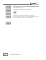
NARDA Safety Test Solutions S.r.l. Socio Unico Sales & Support: Via Leonardo da Vinci, 21/23 20090 Segrate (MI) - ITALY Tel.: +39 02 2699871 Fax: +39 02 26998700 Manufacturing Plant: Via Benessea, 29/B 17035 Cisano sul Neva (SV) Tel.: +39 0182 58641 Fax: +39 0182 586400 http://www.narda-sts.it User’s Manual EMI SIGNAL GENERATOR Including description of: - PMM 3010 EMI SIGNAL GENERATOR 9 kHz ÷ 1 GHz - PMM 3030 EMI SIGNAL GENERATOR 9 kHz ÷ 3 GHz EQUIPMENT SERIAL NUMBER You can find the Serial Number on the rear panel of the instrument. Serial Number is in the form: 0000X00000. The first four digits and the letter are the Serial Number prefix, the last five digits are the Serial Number suffix. The prefix is the same for identical instruments, it changes only when a configuration change is made to the instrument. The suffix is different for each instrument. Document 3010-3030EN-00304-A.32-Copyright © NARDA 2008 NOTE: If the instrument is used in any other way than as described in this Users Manual, it may become unsafe Before using this product, the related documentation must be read with great care and fully understood to familiarize with all the safety prescriptions. To ensure the correct use and the maximum safety level, the User shall know all the instructions and recommendations contained in this document. This product is a Safety Class I instrument according to IEC classification and has been designed to meet the requirements of EN61010-1 (Safety Requirements for Electrical Equipment for Measurement, Control and Laboratory Use). In accordance with the IEC classification, the battery charger of this product meets requirements Safety Class II and Installation Category II (having double insulation and able to carry out mono-phase power supply operations). This product has a Pollution Degree II normally only non-conductive pollution occurs. Occasionally, however, a temporary conductivity caused by condensation must be expected. The information contained in this document is subject to change without notice. EXPLANATION OF ELECTRICAL AND SAFETY SYMBOLS : You now own a high-quality instrument that will give you many years of reliable service. Nevertheless, even this product will eventually become obsolete. When that time comes, please remember that electronic equipment must be disposed of in accordance with local regulations. This product conforms to the WEEE Directive of the European Union (2002/96/EC) and belongs to Category 9 (Monitoring and Control Instruments). You can return the instrument to us free of charge for proper environment friendly disposal. You can obtain further information from your local Narda Sales Partner or by visiting our website at www.narda-sts.it . Warning, danger of electric shock Earth Read carefully the Operating Manual and its instructions, pay attention to the safety symbols. Unit Earth Connection Earth Protection Equipotential EXPLANATION OF SYMBOLS USED IN THIS DOCUMENT : The DANGER sign draws attention to a potential risk to a DANGER person’s safety. All the precautions must be fully understood and applied before proceeding. WARNING The WARNING sign draws attention to a potential risk of damage to the apparatus or loss of data. All the precautions must be fully understood and applied before proceeding. CAUTION The CAUTION sign draws attention against unsafe practices for the apparatus functionality. NOTE: II The NOTE draw attention to important information. Note and symbols Contents Safety recommendations and instructions.………....………………. EC Conformity Certificate…….....................................…….………… Page VIII IX 1. General Information 1.1 Documentation…………………………………………………………. 1.2 Operating Manual changes…………………………………………… 1.3 Introduction to PMM 3010-3030….………………………………….. 1.4 Instrument Items………….……………………………………………. 1.5 Optional accessories……………….…………………………………. 1.6 Other accessories……………………………………………………… 1.7 PMM 3010 Main Specifications………………………………………. 1.8 PMM 3030 Main Specifications………………………………………. 1.9 PMM 3010 Front Panel…………...…………………………………… 1.10 PMM 3010 Rear Panel…………….………………………………… 1.11 PMM 3030 Front Panel……………………………………………… 1.12 PMM 3030 Rear Panel………………………………………………. 1.13 Functional Description……………………………………………….. 1-1 1-1 1-1 1-2 1-2 1-2 1-3 1-4 1-5 1-6 1-7 1-8 1-9 2 Installation 2.1 Introduction……………………………………………………………… 2.2 Initial Inspection……………………………….……………….……….. 2.3 Packing and Unpacking……………………………………….………. 2.4 Preparation for Use……………………………………………………. 2.5 Battery Charger…………………………………………………….….. 2.5.1 To replace the mains connector of the battery charger…………. 2.5.2 To charge the internal battery……………………………………… 2.5.3 Indication of the battery status on the screen and with PW Led.. 2.6 Environment……………………………………………………………. 2.7 Return for Service……………………………………………………… 2.8 Equipment Cleaning……………………………………………………. 2.9 Equipment ventilation………………………………………………….. 2.10 Hardware Installation………………………………………………… 2.11 The user port………………………………………………………..... 2-1 2-1 2-1 2-1 2-1 2-1 2-1 2-2 2-2 2-3 2-3 2-3 2-4 2-5 3 Setup and Panel Instructions 3.1 Introduction……………………………………………………………… 3.2 Display…………………………………………………………………… 3.3 Unit………………………………………………………………………. 3.4 Misc……...………………………………………………………………. 3.5 Panel…..…………….………………………………………………….. 3-1 3-3 3-4 3-4 3-5 4 Operating instructions 4.1 Introduction……………………………………………………………… 4.2 Frequency.……………………………………………………………… 4.3 Level……….……………………………………………………………. 4.4 Modulation………………………………………………………………. 4-1 4-2 4-5 4-8 Contents III 5 How to program 5.1 Introduction………….………………………………………………….. 5.2 Communication…..….…………………………………………………. 5.3 Protocol..………………………………….…………………………….. 5.4 Format……………………….………………………………………….. 5.5 PMM 3010-3030 commands...……………………………………….. 5.5.1 Query Commands…………………………………………………… 5.5.2 Setting commands……..……………………………………………. 5.6 SW-03 Software ……………………………………………………….. 6-1 6-1 6-1 6-1 6-2 6-2 6-4 6-5 6 Updating firmware 6.1 Introduction…………………………………………………………….. 6.2 System requirements…………………………………………………. 6.3 Preparing the Hardware……………………………………………… 6.4 Software Installation………………………………………………….. 6.5 To transfer data………………………………………..……………… 7-1 7-1 7-1 7-2 7-3 IV Contents Figures Page Figure 1-1 1-2 1-3 1-4 1-5 1-6 2-1 3-1 3-2 3-3 4-1 PMM 3010 Front Panel…………...…………………………… PMM 3010 Rear Panel…………….……………………..…… PMM 3030 Front Panel…………………………………..…… PMM 3030 Rear Panel……………………………………..… BP-01 Replaceable battery………………………………….. PMM 3010-3030 Functional Block Diagram…..…………… Operating screen……………………………………………... Auto-Test result……………………………………………….. Main Operating screen……………………………………….. Display setting…………………………………………………. Start-Up screen……………………………………………….. 1-4 1-5 1-6 1-7 1-8 1-8 2-4 3-1 3-1 3-3 4-1 Tables Table 1-1 Page Main Specifications ………..……………………………………. 1-3 Contents V SAFETY RECOMMENDATIONS AND INSTRUCTIONS This product has been designed, produced and tested in Italy, and it left the factory in conditions fully complying with the current safety standards. To maintain it in safe conditions and ensure correct use, these general instructions must be fully understood and applied before the product is used. • When the device must be connected permanently, first provide effective grounding; • If the device must be connected to other equipment or accessories, make sure they are all safely grounded; • In case of devices permanently connected to the power supply, and lacking any fuses or other devices of mains protection, the power line must be equipped with adequate protection commensurate to the consumption of all the devices connected to it; • In case of connection of the device to the power mains, make sure before connection that the voltage selected on the voltage switch and the fuses are adequate for the voltage of the actual mains; • Devices in Safety Class I, equipped with connection to the power mains by means of cord and plug, can only be plugged into a socket equipped with a ground wire; • Any interruption or loosening of the ground wire or of a connecting power cable, inside or outside the device, will cause a potential risk for the safety of the personnel; • Ground connections must not be interrupted intentionally; • To prevent the possible danger of electrocution, do not remove any covers, panels or guards installed on the device, and refer only to NARDA Service Centers if maintenance should be necessary; • To maintain adequate protection from fire hazards, replace fuses only with others of the same type and rating; • Follow the safety regulations and any additional instructions in this manual to prevent accidents and damages. VI Safety considerations EC Conformity Certificate (in accordance with the Directives: EMC 89/336/EEC and Low Voltage 73/23/EEC) This is to certify that the product: PMM 3010 Signal Generator Produced by: NARDA S.r.l. Safety Test Solution Via Benessea 29/B 17035 Cisano sul Neva (SV) – ITALY complies with the following European Standards : Safety: CEI EN 61010-1 (2001) EMC: EN 61326-1 (2007) This product complies with the requirements of Low Voltage Directive 2006/95/CE and with the EMC Directive 2004/108/CE. NARDA S.r.l. EC Conformity Certificate (in accordance with the Directives: EMC 89/336/EEC and Low Voltage 73/23/EEC) This is to certify that the product: PMM 3030 Signal Generator Produced by: NARDA S.r.l. Safety Test Solution Via Benessea 29/B 17035 Cisano sul Neva (SV) – ITALY complies with the following European Standards : Safety: CEI EN 61010-1 (2001) EMC: EN 61326-1 (2007) This product complies with the requirements of Low Voltage Directive 2006/95/CE and with the EMC Directive 2004/108/CE. NARDA S.r.l. EC Conformity VII This page has been intentionally left blank VIII Safety considerations 1 – General Information 1.1 Documentation Enclosed with this manual are: • a service questionnaire to send back to NARDA in case an equipment servicing is needed • an accessories checklist to verify all accessories enclosed in the packaging. Document 3010-3030EN-00304-A.32-@ NARDA 2008 General Information 1-1 1.2 Operating Manual Changes Instruments manufactured after the printing of this manual may have a serial number prefix not listed on the title page; this indicates that instruments with different Serial Number prefix may be different from those documented in this manual. 1.3 Introduction to PMM 3010-3030 PMM 3010-3030 is a powerful wide band signal generator, covering the frequency range from 9 kHz to 1000 MHz (for PMM 3010) and from 9 kHz to 3000 MHz (for PMM 3030). The generator is fully automatic and programmable via a RS232 serial port or an USB. Due to his performances it is an ideal tool for all EMC immunity test applications. The instrument has several features not even included into high cost generator such as: internal pulse modulation, sweeping and correction table downloading (not implemented yet). The PMM 3010-3030 has been designed adopting an innovative philosophy made possible only in the recent years by the availability of superior technology components. Most parts of this instrument are fully digital but not of course the output RF module. It therefore combines into a versatile signal Generator the precision and accuracy of a numeric approach, with flexibility and user friendly approach typical of a modern instrument. 1-2 General Information 1.4 Instrument Items PMM 3010-3030 includes the following items: • PMM Signal Generator • BP-01 Li-ion battery pack ( available only for the versions 3010-02 and 3030-02 ) • External power supply/battery charger; • Flexible black cover/accessories holding; • N-BNC coaxial adapter; • RS232 cable, 2m; • USB cable, 2m; • Operating manual; • PMM 3010-3030 Utility Software on CD; • Certificate of Compliance; • Return for Repair Form. 1.5 Optional accessories PMM 3010-3030 can be used with several optional accessories, the most common being the following: • • • • • • • • • • • • • • • • • • • • • 1.6 Other accessories PMM 6000N RF 10W(15W) amplifier 9 kHz - 230 MHz; PMM 6600 RF Power meter for EMC application; PMM 6600D Slave power meter; Various Amplifiers, depending on the application, 10 kHz - 3 GHz; F-203I-23 Injiection Clamp; F-203I-23-DCN Decoupling Network; F-120-9A Injection Probe; F-33-1 Current Monitor; Wide range of CDNs; 150-50 Calibration kit for CDNs; Load-50 50 Ohm load; 6 dB, 50 Ohm fixed attenuators, 10, 15, 30, 100 W; Coupling/Decoupling Networks; EM current injection clamp RF power meters; Wide range of Antennas; PMM SW06 Conducted Immunity software for IEC 1000-4-6; PMM SW03 Radiated Immunity software for IEC 1000-4-3; 3010-BTA Serial Bluetooth Adapter; 3030-BTA Serial Bluetooth Adapter; GPIB to RS232 Adapter. Of course, the PMM 3010-3030 can be used with other accessories available on the market, like: • Injection Probes and CDNs, any type; • Radiating Antennas; • Various TEM/GTEM Cells. General Information 1-3 1.7 Main Specifications Table 1-1 lists the PMM 3010 performance specifications. The following conditions apply to all specifications: • The ambient temperature shall be 10°C to 40°C Electrical Characteristics TABLE 1-1 Main Specifications Performance Limits Frequency Range Resolution Accuracy 9 kHz to 1 GHz 1 kHz ± 10 ppm (f> 10 MHz) Level Range Resolution Accuracy Output impedance Connector - 107 to + 10 dBm 0.1 dB ± 1 dB dB (Level > -30dBm) 50 Ω N (female) Spectral purity Harmonic < - 30 dBc @ 0 dBm f > 1 MHz AM modulation Internal External Input impedance Connector 2 Hz, 50Hz, 400Hz, 1 kHz - from 10% to 90% 2 Hz to 10 kHz - from 10% to 90% 600 Ω BNC female Pulse modulation Internal ON/OFF ratio 1 Hz 200 Hz ON/OFF ratio @ 0 dBm > 40 dB ON/OFF ratio @ 0 dBm > 40 dB Remote control System interface RS-232, USB 2.0 (rear), USB 2.0 (front: only for future implementation), High Speed Optical Link (2 channels: only for future implementation); User Port; Bluetooth through optional adapter; IEEE-488 (GPIB) external option Connectors DB9, USB-B, USB-A, Optic Fiber, DB-15, IEEE-488 User Port RF Off, RF On, Start/stop test Display Graphical resolution Units 320 x 240 pixel; 16 gray levels dBm, dBµV Operating temperature 10°C to 40°C Power supply 10 - 15 Volt DC, 2,5A; Li-Ion interchangeable battery (3 h operations, average) (available only for the version 3010-02) Standard AC-DC adapter Dimensions 235 x 105 x 335 mm (WxHxD) Weight Version 3010-01 (without battery ) 3.5kg Version 3010-02 (with battery 7.4V 6.6Ah Li-ion ) 4.3Kg 1-4 General Information 1.8 Main Specifications Table 1-1 lists the PMM 3030 performance specifications. The following conditions apply to all specifications: • The ambient temperature shall be 10°C to 40°C Electrical Characteristics TABLE 1-2 Main Specifications Performance Limits Frequency Range Resolution Accuracy 9 kHz to 3 GHz (*) 1 kHz ± 10 ppm (f> 10 MHz) Level Range Resolution Accuracy Output impedance Connector - 107 to + 10 dBm 0.1 dB ± 1 dB dB (Level > -30dBm) 50 Ω N (female) Spectral purity Harmonic < - 30 dBc @ 0 dBm f > 1 MHz AM modulation Internal External Input impedance Connector Pulse modulation Internal ON/OFF ratio 2 Hz, 50Hz, 400Hz, 1 kHz - from 10% to 90% 2 Hz to 10 kHz - from 10% to 90% 600 Ω BNC female 1 Hz 200 Hz ON/OFF ratio @ 0 dBm > 40 dB ON/OFF ratio @ 0 dBm > 40 dB Remote control System interface RS-232, USB 2.0 (rear), USB 2.0 (front: only for future implementation), High Speed Optical Link (2 channels: only for future implementation); User Port; Bluetooth through optional adapter; IEEE-488 (GPIB) external option Connectors DB9, USB-B, USB-A, Optic Fiber, DB-15, IEEE-488 User Port RF Off, RF On, Start/stop test Display Graphical resolution Units 320 x 240 pixel; 16 gray levels dBm, dBµV Operating temperature 10°C to 40°C Power supply 10 - 15 Volt DC, 2,5A; Li-Ion interchangeable battery (3 h operations, average) (available only for the version 3030-02) Standard AC-DC adapter Dimensions 235 x 105 x 335 mm (WxHxD) Weight Version 3030-01 (without battery ) 3.5kg Version 3030-02 (with battery 7.4V 6.6Ah Li-ion ) (*) Firmware release 1.06 or higher 4.3Kg General Information 1-5 1.9 PMM 3010 Front Panel Fig. 1-1 PMM 3010 Front Panel Legend from left to right: - USB USB 2.0 connection port (future implementation only) - PW Power led Indicates the power status - DISPLAY Main display To graphically show the instrument status - User keys 5 command keys To select the various available functions - Controls Rotary Knob, Left and Right (decrease / increase) Arrow Keys; Esc; Enter/Switch Key The Rotary Knob and the Arrows Keys can be used to increase and decrease the setting values; the Esc key allows to return to the previous status/display; the Enter/switch key is used to confirm a set value and to switch On and Off the instrument. - RF Output Main generator RF output connector 1-6 General Information 1.10 PMM 3010 Rear Panel PS1 PS2 Fig. 1-2 PMM 3010 Rear Panel Legend from left to right: - RS232 9 pin, DB9 connector - GPIB IEEE488 I/O Port (External Option) - USER PORT User I/O Port - USB Fully functional USB 2.0 Port - LINK1/LINK2 Optical link connectors for PMM equipments (for future implementation) - Power Supply Power Supply Inputs for use to power the apparatus and simultaneously charge its battery (PS1) and to simply charge the battery when it’s out of the Generator (PS2) ( Version 3010-02 ). - MOD External modulation input - REF External Reference input/output - Fan Cooling Fan controlled by firmware - Replaceable Li-Ion Battery (Fig. 1-2) ( available only for the version 3010-02 ) with main Battery Charger connector - Earth ground connector - Product Label and Serial Number General Information 1-7 1.11 PMM 3030 Front Panel Fig. 1-3 PMM 3030 Front Panel Legend from left to right: - USB USB 2.0 connection port (future implementation only) - PW Power led Indicates the power status - DISPLAY Main display To graphically show the instrument status - User keys 5 command keys To select the various available functions - Controls Rotary Knob, Left and Right (decrease / increase) Arrow Keys; Esc; Enter/Switch Key The Rotary Knob and the Arrows Keys can be used to increase and decrease the setting values; the Esc key allows to return to the previous status/display; the Enter/switch key is used to confirm a set value and to switch On and Off the instrument. - RF Output Main generator RF output connector 1-8 General Information 1.12 PMM 3030 Rear Panel PS1 PS2 Fig. 1-4 PMM 3030 Rear Panel Legend from left to right: - RS232 9 pin, DB9 connector - GPIB IEEE488 I/O Port (External Option) - USER PORT User I/O Port - USB Fully functional USB 2.0 Port - LINK1/LINK2 Optical link connectors for PMM equipments (for future implementation) - Power Supply Power Supply Inputs for use to power the apparatus and simultaneously charge its battery (PS1) and to simply charge the battery when it’s out of the Generator (PS2) ( Version 3030-02 ). - MOD External modulation input - REF External Reference input/output - Fan Cooling Fan controlled by firmware - Replaceable Li-Ion Battery (Fig. 1-4) ( available only for the version 3030-02 ) with main Battery Charger connector - Earth ground connector - Product Label and Serial Number General Information 1-9 Fig. 1-5 BP-01 Replaceable Battery 1.13 Functional Description The PMM 3010-3030 features a completely new Generator architecture based on the most recent DSP technology, as shown in the diagram below. Fig. 1-6 PMM 3010-3030 Functional BLOCK Diagram 1-10 General Information 2 - Installation 2.1 Introduction This section provides the information needed to install your PMM 30103030. It includes the information pertinent to initial inspection and power requirements, connections, operating environment, instrument mounting, cleaning, storage and shipment. 2.2 Initial Inspection When receiving the equipment, first inspect the shipping box for any damage. If the shipping box is damaged, it should be kept until the contents of the shipment have been checked for completeness and the instrument has been checked mechanically and electrically. 2.3 Packing and Unpacking Verify the availability of all the shipped items with reference to the shipping check list enclosed with the Operating Manual. Notify any damage to the forwarder personnel as well as to your NARDA Representative. To avoid further damage, do not turn on the instrument when there are signs of shipping damage to any portion of it. 2.4 Preparation for Use This is a Safety Class I apparatus, but it is also equipped with a protective/functional earth terminal on the rear panel. A good safety/functional ground connection should be provided before to operate the Generator. The instrument are available in two different version: • 3010-01 or 3030-01 with only external power supply . • 3010-02 or 3030-02 with external power supply and the Li-ion Battery Pack BP01 ( 7.4V Li-Ion 6.6Ah ) . 2.5 Battery charger The battery charger supplied with the Generator can work at either 50 Hz or 60 Hz with a supply voltage rated between 100 and 240 Volt. It is supplied, when needed, with different connectors to fit all the possible outlets in accordance with the various National standards. - Battery charger: DC, 10 - 15 V, ~ 2500 mA => DC Connector + 2.5.1 To replace the mains connector of the battery charger To replace the mains connector, simply remove the one installed on the battery charger sliding it off, and insert the one that fits the outlets in use. 2.5.2 To charge the internal battery In order to guarantee the best autonomy of the internal battery, we recommend to fully recharge it before using the Generator. To charge the battery, simply connect the battery charger to the mains power socket and then insert the DC output connector of the battery charger to the input CHARGER on the rear panel of the Generator. The average charging time is 6 hours when starting with a completely discharged battery. ALWAYS connect the battery charger to the mains power BEFORE connecting the DC output to PMM 3010-3030. The battery charger has an internal protective circuit that will not let it work if there is a load connected to the output connector before the connection to the mains is done. Document 3010-3030EN-00304-A.32-@ NARDA 2008 Installation 2-1 The charge status of the battery is displayed on the top right-hand corner 2.5.3 Indication of the of the screen in most of the Generator modes. The symbol of a small battery status on the screen and with battery will be filled up proportionally to the status of the battery charge. PW led When the battery is not under charge, the actual voltage value is displayed under the symbol and the length of the black bar filling the symbol indicates the available autonomy still remaining. When the battery charger is connected to the PMM 3010-3030 the indication “PWR” appears just below to the battery icon and the front panel PW led becomes yellow if the Generator is switched on and red if the Generator is off. The battery charging is suspended or ends automatically when one of the following events occurs: - the full capacity of the battery has been achieved, - the internal temperature of the battery is higher then a preset safety threshold, - the charging time limit has been exceeded. Both during recharging and when charge is completed PMM 3010-3030 is ready for use. The PW led on the front panel blinks green when the battery voltage drops below 7,0V to warn the Operator that the instrument is running out of battery. To prevent any damage to the battery, the PMM 3010-3030 automatically switches itself off when the battery voltage falls below 6,5V. In order to keep the batteries fully functional, it is crucial to have a complete charge-discharge cycle before storing them for periods longer than 4 months. Therefore, it is suggested to recharge the batteries at least every 4 months even when the Generator has not been used. 2.6 Environment The operating environment of the Generator is specified to be within the following limits: • Temperature • Humidity • Altitude +10° to +40° C < 90% relative 4000 meters The instrument should be stored and shipped in a clean, dry environment which is specified to be within the following limitations: • Temperature • Humidity • Altitude 2-2 Installation -40° to + 50° C < 95% relative 15.000 meters 2.7 Return for Service If the instrument should be returned to NARDA for servicing, please complete the questionnaire enclosed with the Operating Manual and attach it to the instrument. To minimize the repair time, be as specific as possible when describing the failure. If the failure only occurs under certain conditions, explain how to duplicate the failure. If possible, reusing of the original packaging to ship the equipment is preferable. In case other package should be used, ensure to wrap the instrument in heavy paper or plastic. Use a strong shipping box and use enough shock absorbing material all around the equipment to provide a firm cushion and prevent movement in the shipping box; in particular protect the front panel. Seal the shipping box securely. Mark the shipping box FRAGILE to encourage careful handling. 2.8 Equipment Cleaning Use a clean, dry, non abrasive cloth for external cleaning of the equipment. To clean the equipment do not use any solvent, thinner, turpentine, acid, acetone or similar matter to avoid damage to external plastic or display surfaces. 2.9 Equipment ventilation To allow correct equipment ventilation ensure that the vent grids on the rear panel and on the bottom of the Generator are free by any obstructing object. Installation 2-3 2.10 Hardware Installation PMM 3010-3030 is delivered from factory ready to use. Remove the Generator from cardboard shipping box and keep the “ON” button pressed until the PW Led lights up (about 1 second), then release the button. To avoid unwanted starts, if the “ON” button is kept pressed for a too short time or for more then 2 seconds the instrument is switched automatically off. After having been switched ON, the PMM 3010-3030 boots with its internal BIOS and runs the firmware which manages the Generator. At the beginning the instrument performs a diagnostic test to check if everything is working properly. The boot sequence is very fast and the Generator is ready to use in a couple of seconds after having pressed the ON button. During the switch-on procedure the LCD displays the results of the auto-test and the release – and date - of the loaded firmware: if the display shows “OK” it means that the PMM 3010-3030 is working properly. When the sequence is completed the main screen shows the test results and the main functional keys on the right of the LCD display: the Generator is now ready to operate. Display at start-up showing auto-test result, diagnostic info and Start button. To avoid damages to the RF power stage of the generator it is recommendable not to leave the output connector without any 50 Ω load. Also never inject signals into the output connector. If auto-test is normally passed, PMM 3010-3030 switches automatically to the operation mode, displaying the following screen. Fig. 2-1 Operating Screen 2-4 Installation 2.11 The User Port The PMM 3010-3030 features on the rear panel a programmable User Port that can be used to drive (or to be driven by) external devices or, more generally, to input/output signals and data. The User Port can easily be programmed and managed; the connector has the following hardware connection: PIN # Signal 1 2 3 4 5 6 7 8 and 9 10 11 12 13 14 15 IN3 IN1 + 12 VDC (max 50 mA) OUT 0 OUT 2 OUT 4 USR-MISO IN 2 IN 0 GND OUT 1 OUT 3 USR-MOSI USR-CLK Data output (OUT 0 to OUT 4) and input (IN 0 to IN 3) are opto-coupled TTL level with max. 1 mA draining. Every other detail about User Port functionality is described in a separate and more specific manual, available upon request. Installation 2-5 This page has been left blank intentionally 2-6 Installation 3 – Set-Up and Panel Instructions 3.1 Introduction PMM 3010-3030 has been designed with an user friendly interface to be easily used by EMC engineer as well by not-skilled personnel. All the functions can be recalled by the front panel keyboard and rotary knob. The internal firmware Start-Up process performs an Auto-Test immediately after having switched ON the equipment and all resulting data are reported on the LCD display, as showed in the following screenshot: Fig. 3-1 Auto-Test Result If the Auto-Test is successfully completed the PMM 3010-3030 automatically switches to the Main Operating Screen 1 Fig. 3-2 Main Operating Screen Document 3010-3030EN-00304-A.32-@ NARDA 2008 Set-Up and Panel Instructions 3-1 Press this function key in the main menu to enter in the Configuration window, which allows the Operator to set the global parameters of the receiver: display options, etc. The Config function is divided into four sub-windows: • • • • Display Unit Misc Panel Always use Esc button to return to the previous view/condition. (for a more comfortable use, only in this case the Main Operating Menu is recalled when pushing Esc button from these sub-windows) 3-2 Set-Up and Panel Instructions 3.2 Display The Display setup has five function keys: • • • • 3 Dim Aspect: to choose between standard and 3-dimensional keys Inverse: to reverse the text and background colors; Style: to switch between font style 0 and font style 1; Key border: to choose the style of the key borderlines between three different possibilities; • Contrast / Back Light (toggle switch): to adjust the backlight and contrast settings by the rotary knob. Fig. 3-3 Display setting Set-Up and Panel Instructions 3-3 3.3 Unit Entering in the Unit menu it is possible to change the indicated unit used to display the measured levels. The available units are dBµV and dBm. In a 50 Ohm system the relationship between dBm and dBµV is: dBµV = dBm + 107 i.e., 0 dBm (1 mW) = 107 dBµV 3.4 Misc 3-4 Entering the Misc menu it is possible to select the Internal Frequency Reference or the External one. In the first situation (Int. Ref.) the internal 10 MHz precise TCXO is selected and a 10 MHz, 0 dBm output signal becomes available at the REF connector on the rear panel, what could be useful to synchronize other instruments. When the Ext. Ref. is selected the REF connector becomes an input which an external 10 MHz, 0 dBm signal should be connected to. The impedance for both output and input reference is 50 Ω. Set-Up and Panel Instructions 3.5 Panel The Panel function allows the User to store up to 2 different setups that can be recalled any time. Pressing Save #1 or Save #2 the actual setup is stored in the internal memory; with the two Recall buttons the corresponding setup is recovered from receiver’s memory. Please remember each time one of the Save buttons is pressed, the stored set-up is overwritten by the new one: the saved setups are therefore kept memorized in the receiver until a new set-up is stored in the same memory. The Default button can be used to load a factory default setup saved into the memory as standard settings at time of manufacturing. Set-Up and Panel Instructions 3-5 This page has been left blank intentionally 3-6 Set-Up and Panel Instructions 4 – Operating Instructions 4.1 Introduction PMM 3010-3030 has been designed with an user friendly interface to be easily operated by EMC engineers as well as by not-skilled personnel. All the functions can be recalled through front panel keyboard and rotary knob. In the previous chapter it has been already explained that diagnostic information are displayed after switching ON the unit and, soon after, the screen is automatically switched to the Main Operating Window, where it will be possible to select all operating conditions for 3010-3030 generator. Fig. 4-1 Start-Up Screen In case the screen would not be switched automatically to the operating one for some reasons, press the Start function key to enter the Operating Window, which allows the operator to set the Frequency, Level, Modulation, Configuration and Enable/Disable of the RF Output of the generator. This is the operating mode in which the instrument works as a common stand alone signal generator. On the screen of the operating mode all the relevant information are reported. In the 3D gray box the User can read the generator frequency and level; in the other smaller boxes are the information concerning Modulation, Frequency step, Level step and the status of the RF Output. Document 3010-3030EN-00304-A.32-@ NARDA 2008 Operating Instructions 4-1 4.2 Frequency Pushing Freq button opens a sub-menu. The Frequency menu is divided into five sub functions: • • • • • Enter Knob Arrows Step Mode RF Out On-OFF To adjust the frequency value the operator can underline proper digit simply pressing the Left ( Å ) and Right ( Æ ) Arrows keys on the front panel, then decrease or increase the value by rotating the Rotary Knob. Always use Esc button to return to the previous view/condition. This button is used to enter the numerical value of desired frequency. When it is pressed, the PMM 3010-3030 shows a small window in the bottom left corner of the display, in which the set frequency will appear. The value is entered by pressing the five Function Keys on the right side of the display. Using Left (Å) and Right (Æ) Arrows keys, displayed values will be scrolled, providing alternatively 0 to 4 or 5 to 9 numbers, Frequency Units, Dot Pitch and Back Space; proper value to be input will then be selectable through one of the five Function Keys. Pressing 0 as first number the decimal dot appears automatically. Input of selected value will be completed soon after pushing the Frequency Unit button (kHz, MHz or GHz). With the Esc button the original view can be restored at any moment. 4-2 Operating Instructions Allows the User to set the Tuning Frequency Step associated to the Rotary Knob. To input desired Step in frequency simply use the Function and Arrows Keys as for the previous Enter button. After pressing the Knob button, at the bottom left corner of the screen the small window showed below appears. The frequency step of the rotary knob can be directly edited into this window, inputting data through the five Function Keys as usual. Using Left (Å) and Right (Æ) Arrows keys, displayed values will be scrolled, providing alternatively 0 to 4 or 5 to 9 numbers, Frequency Units, Dot Pitch and Back Space; proper value to be input will then be selectable through one of the five Function Keys. Pressing 0 as first number the decimal dot appears automatically. Input of selected value will be completed soon after pushing the Frequency Unit button (kHz, MHz or GHz). For instance, default unit is MHz, then it could be also possible to input for example100 kHz as 0,1 soon followed by Return (◄─┘), or 10 kHz as 0,01 and 1 kHz as 0,001, always followed by Return (◄─┘). This button works like the Knob one, but defines the Frequency Step used to increase or decrease the generator frequency through the Left (Å) and the Right (Æ) Arrows keys on the front panel. Operating Instructions 4-3 Pressing this key the User toggles between the two modes of operation in which the frequency can be changed or “by the Cursor & Knob” or “by the Steps through the Knob and the Arrow Keys”. When the Step mode is activated, the digit underline (cursor) disappears and the section named “Freq. Step (MHz)” becomes black, which means these values become active for frequency changes by Knob or Arrows, according to respective steps previously set in corresponding menus. When the Cursor & Knob mode is returned, pushing again the Step Mode button, the “Freq. Step (MHz)” window becomes gray to indicate Step Mode through Knob and Arrows is not active anymore. The fifth button in the Frequency menu is used to switch the RF Output On or OFF. When the RF Output is active the corresponding “ON” indication on the screen is highlighted. To prevent accidental damage of PMM 3010-3030 or other equipments connected in the testing chain (amplifier, power meter, etc.), be sure all devices are properly connected before switching ON this RF generator. In case of using PMM 3010-3030 connected to amplifiers and antennas in chain, be sure to keep all doors of protected shielded enclosure properly closed before switching ON the RF Output, in order to avoid any possible injury by electromagnetic pollution and subsequent legal actions by local government. 4-4 Operating Instructions 4.3 Level Pushing Level button opens a sub-menu. The Level menu is again divided into five sub-functions: • • • • • Enter Knob Arrows Step Mode RF Out On-OFF In this mode the RF Output Level can be adjusted by pressing the Arrow Keys to move the cursor below desired digit, then rotating the Knob on the front panel to increase or decrease the output level. Always use Esc button to return to the previous view/condition. This button is used to directly input the numerical output level. When it is pressed, the PMM 3010-3030 shows a small window at the bottom left corner of the display, in which the new value will be inserted. The value is entered by pressing the five Function Keys on the right side of the display. Using Left (Å) and Right (Æ) Arrows keys, displayed values will be scrolled, providing alternatively 0 to 4 or 5 to 9 numbers, “+/-” sign, Dot Pitch and Back Space; proper value to be input will then be selectable through one of the five Function Keys. Pressing 0 as first number the decimal dot appears automatically. Input of selected value will be completed soon after pushing the Return (◄─┘) button on the front panel. With the Esc button the original view can be restored at any moment. Operating Instructions 4-5 Allows the User to set the Output Level Step associated to the Rotary Knob. To input desired Step in frequency simply use the Function and Arrows Keys as for the previous Enter button. After pressing the Knob button, at the bottom left corner of the screen the small window showed below appears. The frequency step of the rotary knob can be directly edited into this window, inputting data through the five Function Keys as usual. Using Left (Å) and Right (Æ) Arrows keys, displayed values will be scrolled, providing alternatively 0 to 4 or 5 to 9 numbers, “+/-” sign, Dot Pitch and Back Space; proper value to be input will then be selectable through one of the five Function Keys. Pressing 0 as first number the decimal dot appears automatically. Input of selected value will be completed soon after pushing the Return (◄─┘) button on the front panel. The default unit is dBm (dBµV can be selected from the Config menu in the initial screen). This button works like the Knob one, but defines the Level Step used to increase or decrease the generator frequency through the Left (Å) and the Right (Æ) Arrows keys on the front panel. 4-6 Operating Instructions Pressing this key the User toggles between the two modes of operation in which the output level can be changed or “by the Cursor & Knob” or “by the Steps through the Knob and the Arrow Keys”. When the Step mode is activated, the digit underline (cursor) disappears and the section named “Level Step (dB)” becomes black, which means these values become active for output level changes by Knob or Arrows, according to respective steps previously set in corresponding menus. When the Cursor & Knob mode is returned, pushing again the Step Mode button, the “Level Step (dB)” window becomes gray to indicate Step Mode through Knob and Arrows is not active anymore. The fifth button in the Frequency menu is used to switch the RF Output On or OFF. When the RF Output is active the corresponding “ON” indication on the screen is highlighted. In order to provide the User with signals even lower or higher than those in specifications (guaranteed ones), the actual minimum level that could be displayed on the screen is -107 dBm, while the maximum could be +20 dBm. To set the appropriate unit for your convenience it is simply necessary to go to the Setup mode and enter the Unit selection menu as described in paragraph 3.4. To prevent accidental damage of PMM 3010-3030 or other equipments connected in the testing chain (amplifier, power meter, etc.), be sure all devices are properly connected before switching ON this RF generator. In case of using PMM 3010-3030 connected to amplifiers and antennas in chain, be sure to keep all doors of protected shielded enclosure properly closed before switching ON the RF Output, in order to avoid any possible injury by electromagnetic pollution and subsequent legal actions by local government. Operating Instructions 4-7 4.4 Modulation The Modulation menu has four sub-functions: • • • • Mode Depth Int/Ext Mod ON-OFF In this mode the output power level can still be changed by Cursor & Knob if the Level was lately chosen before entering the Modulation screen, simply moving the cursor below the desired digit and rotating the knob on the front panel to increase or decrease it. By pressing the Mode key it is possible to select the proper modulation mode between the following choices: AM 1kHz, AM 400Hz AM 50Hz AM 2Hz Pulse 200Hz Pulse 1Hz The chosen Mode is shown in the Modulation section, which becomes black in color on the display. After selecting desired mode press Mod ON-OFF button to activate the modulation. In the same way, pressing again the key, the modulation is switched back OFF. Selected Status is always displayed in the same section. Not only modulation frequency and mode are selectable, but also Modulation Depth can be adjusted. Pressing this key the User can input the modulation depth percentage. The percentage is shown in the Modulation section on the display. The generator is internally equalized to get the same modulation depth over the whole frequency band. The User may enter a value even beyond the range indicated in the main specifications, and actually the depth can be set between 10% and 95%. 4-8 Operating Instructions This function key works as a toggle switch to select between the internal modulating sources and the external one. The corresponding indication is shown in the Modulation section at left side of the screen. When the internal modulation is chosen the related mode can be selected by the Mode key as described. Setting the External modulation the generator uses the signal coming from the MOD connector, located on the rear panel, as the source for the RF modulator. Pay attention not to overload the External Modulation input. The maximum allowed voltage is 10 Vpp with high impedance. Connect your source only if you are pretty sure you’re providing less than 10 Vpp (about 131 dBµV). Before to apply an unknown signal to PMM 3010-3030 generator, use an oscilloscope or an audio frequency voltmeter to measure it. If needed, add an external high impedance attenuator on the input signal line. An Overload indication will automatically appear on the screen to inform the Operator that the level of the applied signal for external modulation is too high: to avoid errors and even damages to the generator it is then necessary to reduce the voltage of the modulating signal. When the modulation is activated the maximum available output power level is reduced by 6dB. So, using modulated signals, the max available power level is +4dBm. When the modulator is active the level displayed is, as the theory defines, the power of its carrier. So, for example, when a 0 dBm fully modulated signal is generated, the effective output power is about +1.76 dBm. With the last key appearing in the Modulation functions menu it is possible to enable or disable the modulator. This is a toggle switch by which the modulation can be set either ON or OFF; default is not active. In the Modulation section on the screen the Status is always displayed. The modulator of the PMM 3010-3030 runs in an innovative way. Along its path, the modulating signal is at first converted in digital by an ADC module, then conditioned by the internal DSP chain and, soon after, converted in analog voltage again by a fast DAC circuit. Such analog voltage is then used to modulate the carrier through a linear RF modulator. The aim of this numeric approach is to guarantee linear, stable and versatile modes of modulation with any base band frequency that even future rules and recommendations could require. Operating Instructions 4-9 This page has been left blank intentionally 4-10 Operating Instructions 5 – Remote control 5.1 Introduction PMM 3010-3030 has been designed to allow remote control operations through its either RS232 or USB (Rear) ports. When using RS232 you can use only one instrument connected to PC serial port. If using USB you can connect other instruments to the free RS232 port and the PMM 3010-3030 Generator to the USB 2.0. PMM 3010-3030 uses the same commands protocol for both communications. 5.2 Communication Half duplex communication is implemented. The RS232 port has a DB-9 female connector and the USB 2.0 has a USB-B connector. A built-in automatic tool identify the type of communication used. Standard communication is implemented at 115200 bit/sec with 8 bit words, one stop bit and no parity (115200 N 8 1). 5.3 Protocol Be aware that only the PC can send the commands. PMM 3010-3030 will answer when is inquired only. The communication uses strings with variable byte width. The characters used inside the strings are in ASCII format (00 - 127) at 7 bits. The most significant bits are ignored in reception and set to 0 during transmission. Every string starts with the special character “#” and stops with “*”. 5.4 Format Commands are made of ASCII string delimited character “#” (0x23) and the character “*”(0x2A) Replies are terminated with <CR><LF> (\r\n) Document 3010-3030EN-00304-A.32-@ NARDA 2008 Remote Control 5-1 5.5 PMM 3010-3030 COMMANDs Following are Commands to control and set various operating modes of PMM 3010-3030, that can be distinguished in two main groups: • • 5.5.1 QUERY Commands Query Commands Setting Commands Description ?IDN This query command #?IDN* sends back a string containing information about model, release and date of firmware Note that two <LF> are appended to the string before the terminator. Example of reply: IDN=3030.FW – 1.12 20/10/07<LF><LF> ?S/N This query command #?S/N* sends back a string containing 3010-3030 serial number internally stored by manufacturer. Example of reply: S/N=000WE50327 ?R/N This query command #?R/N*sends back a string containing RF MODULE serial number internally stored by manufacturer. Example of reply:R/N=RF-0000001 ?CFR This query command #?CFR*sends back a string expressing the tuning frequency. Example of reply:CFR= 20.000MHz which means that the tuned frequency in manual mode is 20MHz ?CLV This query command #?CLV*sends back a string expressing the RF OUT Level expressed in dBm regardless the set unit in the 3010-3030 Example of reply:CLV= -20.00 which means that the level carrier is 20dBm ?RFO This query command #?RFO*sends back a string expressing the status of RF OUTPUT to N connector The reply is either RFO= Off or RFO=On ?STS This query command #?RFO*starts a diagnostic test and sends back a string expressing the result of the test. The reply is STS=<status> in Hexadecimal representing all the flags. In case no error were detected the replay is STS=0x0000 Table in progress PLL Main Unlock PLL II Unlock Unlock main PLL or controlling voltage out of range Table needs to be remade RF Module ADC not recognized 5-2 Remote control 0x0008 0x0004 0x0002 0x0010 0x0020 0x0040 ?MOD This query command #?MOD*sends back a string expressing the Modulation Status The reply is a string divided into 3 fields as follows: MOD= Type, Depth, Status Where: • Type is the kind of modulation and can be among the following o Ext o AM 1kHz o AM 400Hz o AM50Hz o AM2Hz o Pulse 200Hz o Pulse 1Hz • Depth is the depth of modulation • Status shows whether modulation is ON or OFF Here below are some reply examples. MOD=AM 1kHz:90.0%;OFF MOD=AM 400Hz:90.0%;OFF MOD=Ext:90.0%;OFF MOD=AM 400Hz:10.0%;ON ?UPP ?DPY ?TMP This query command #?UPP* sends back a string expressing the status of PINs of the User port. Each Pin has own contribution according to its index as follow: IN0=2^0 IN1=2^1 IN2=2^2 IN3=2^3 Thus, the number read back is the sum of each weighted contribution Example of reply: UPP=5 means that User port Pins IN0 and IN2 are highlevel while user port Pins IN1 and IN3 are low-level This query command #?DPY* sends back a bitmap of display hardcopy This query command #?TMP* sends back a string expressing the internal 3010-3030 temperature in degree centigrade. Example of reply: TMP=26.50 Remote Control 5-3 5.5.2 SETTING Commands SCFR f This setting command sets the tuning frequency. The string (f) can be in exponential form and should be expressed in MHz. The reply is CFR=OK which acknowledges the command has been granted or CFR=SERR if the command has been ignored. Example: #SCFR 150* Sets the carrier frequency to 150 MHz SCLV I This setting command sets the level of carrier. The string (I) can be in exponential form and should be expressed in dBm. The reply is CLV=OK which acknowledges the command has been granted or CLV=SERR if the command has been ignored. Example: #CLV -20* Sets the level of carrier to -20 dBm SRFO stat This setting command switches OFF or ON RF OUT on N connector. The string “stat” must be either OFF or ON otherwise the command is ignored. The reply is RFO=OK which acknowledges the command has been granted or RFO=SERR if the command has been ignored. Example: #RFO ON* switches ON or OFF RF OUT on N connector SMON stat This setting command switches OFF or ON the modulation. The string “stat” must be either OFF or ON otherwise the command is ignored The reply is MON=OK which acknowledges the command has been granted or MON=SERR if the command has been ignored Example: #SMON ON* turns the modulation ON SMDE d This setting command sets the type of modulation. The reply is MDE=OK which acknowledges the command has been granted or MDE=SERR if the command has been ignored. Example: #SMDE 50* sets the depth of modulation to 50.0% MSTY id This setting command sets the type of modulation. The reply is STY=OK which acknowledges the command has been granted or STY=SERR if the command has been ignored. The index (id) selects among the following list: 0. Ext 1. AM 1kHz 2. AM 400Hz 3. AM 50Hz 4. AM2Hz 5. Pulse 200Hz 6. Pulse 1Hz Example: #SMTY 1* sets the type of modulation to AM 1kHz 5-4 Remote control SUPP n This setting command #SUPP n* output on the User port bit by bit the argument n: Each Pin has its own contribution according to its as follows: OUT0=2^0 OUT1=2^1 OUT2=2^2 OUT3=2^3 SupplyOFF=2^4 Thus, the argument sent is the sum of each weitghde contribution. The reply is UPP=OK which acknowledged the commend has been granted or UPP=SERR if the command has ignored (IE argument>31) Example: SUPP 5 will set • User port pins OUT0 and OUT2 to high level • User port pins OUT1 and OUT3 are low level • User port power Supply (+12V) ON 5.6 SW-03 Software Refer to PMM SW-03 Operating Manual for the instructions concerning how to use the PMM 3010-3030 within the Immunity system software. Remote Control 5-5 This page has been left blank intentionally 5-6 Remote control 6 - Updating firmware 6.1 Introduction The PMM 3010-3030 features a simple and user-friendly method for updating its internal firmware through a Personal Computer (PC). This section provides all the information required for easy updating. 6.2 System requirements The minimum requirements to allow the software to operate properly are the following: • 486 Processor or Pentium • 16 Mb of RAM • at least 10 Mb of free space on hard disk • 1 free Serial Port (RS-232), or, alternatively, a USB/RS-232 Adapter with related driver • Windows Operating System™ 95/98/2000/XP 6.3 Preparing the Hardware Connect the RS-232 cable supplied with PMM 3010-3030 between the 9 pin socket located on the back panel of PMM 3010-3030 and a RS232 port on the PC side, directly or through a RS-232/USB Adapter separately purchased (once related driver has been properly installed). The first available RS-232 port will be automatically detected by the Firmware Update Program during installation. In case of troubles please check port assignments on the PC through the Control Panel utility. Document 3010-3030EN-00304-A.32-@ NARDA 2008 Updating Firmware 6-1 6.4 Software Installation The Update Firmware Program is installed together with the PMM Software Utility, provided on a CD-Rom with PMM 3010-3030 Generator. Once the Software has been installed in the PC, another item is created in the Programs list at Start Menu, which is “3030 Accessories”, from where the “3030 Update” program can be easily run Click on “3030 UPDATE” (3030UP.EXE) once for running the update program, so getting the following window: Please be sure the new FW file named “3030FW.bin” is stored in the same directory of the 3030UP.exe file, otherwise just copy it there before performing the upgrade. Be sure batteries of PMM 3010-3030 and connected Laptop (PC) are fully charged before performing the FW Upgrade, otherwise the upgrade progress could not terminate properly. Alternatively, be sure to have both PMM 3010-3030 and Laptop (PC) powered through their respective AC/DC power adapters. Anyway, even in case of failure, the internal BIOS will never be corrupted and you’ll just need to repeat the procedure once more (this is a unique feature!). 6-2 Updating Firmware 6.5 To transfer data To finally perform the Firmware Update, switch OFF the PMM 3010-3030 at first, run the “3030 Update” to make the related window appearing with the “Waiting for BIOS” writing at the bottom, then switch ON the PMM 3010-3030 and the FW download will begin automatically. During the firmware storing procedure, a blue bar will progress from left to right in the window of the PC, showing percentage of downloading time by time until 100%. In the meanwhile on the 3010-3030 display the BIOS page appears, showing again the updating status. When FW download finishes, following message appears to show that everything was properly completed: In case of failure, an error message is showed instead. After Firmware Update is successfully completed, switch OFF and then ON again the PMM 3010-3030, looking at screen. Now at the top of the display a different FW Release Number and Date is showed after “3030-FW -…”, as per the following: In case the release should not comply with what expected, just check about the FW file used during installation or get in contact with the nearest NARDA Local Distributor. It is now possible to disconnect the cable connected to the PC, with the PMM 3010-3030 Generator either switched On or Off. To obtain up-to-date Firmware or PC Utility for PMM 3010-3030, the user can contact his NARDA agent or download it directly from Support area of EMC Product Range on the following Web Site: www.narda-sts.it. Updating Firmware 6-3 This page has been left blank intentionally 6-4 Updating Firmware NARDA Safety Test Solutions S.r.l. Socio Unico Sales & Support: Via Leonardo da Vinci, 21/23 20090 Segrate (MI) - ITALY Tel.: +39 02 2699871 Fax: +39 02 26998700 Manufacturing Plant: Via Benessea, 29/B 17035 Cisano sul Neva (SV) Tel.: +39 0182 58641 Fax: +39 0182 586400 http://www.narda-sts.it Mod. 18-1 Caro cliente grazie per aver acquistato un prodotto NARDA! Sei in possesso di uno strumento che per molti anni ti garantirà un’alta qualità di servizio. NARDA riconosce l'importanza del Cliente come ragione di esistenza; ciascun commento e suggerimento, sottoposto all'attenzione della nostra organizzazione, è tenuto in grande considerazione. La nostra qualità è alla ricerca del miglioramento continuo. Se uno dei Suoi strumenti NARDA necessita di riparazione o calibrazione, può aiutarci a servirla più efficacemente compilando questa scheda e accludendola all’apparecchio. Tuttavia, anche questo prodotto diventerà obsoleto. In questo caso, ti ricordiamo che lo smaltimento dell'apparecchiatura deve essere fatto in conformità con i regolamenti locali. Questo prodotto è conforme alle direttive WEEE dell’Unione Europea (2002/96/EC) ed appartiene alla categoria 9 (strumenti di controllo). Lo smaltimento, in un ambiente adeguato, può avvenire anche attraverso la restituzione del prodotto alla NARDA senza sostenere alcuna spesa. Può ottenere ulteriori informazioni contattando i venditori NARDA o visitando il nostro sito Web www.narda-sts.it. Dear Customer thank you for purchasing a NARDA product! You now own a high-quality instrument that will give you many years of reliable service. NARDA recognizes the importance of the Customer as reason of existence; in this view, any comment and suggestion you would like to submit to the attention of our service organization is kept in great consideration. Moreover, we are continuously improving our quality, but we know this is a never ending process. We would be glad if our present efforts are pleasing you. Should one of your pieces of NARDA equipment need servicing you can help us serve you more effectively filling out this card and enclosing it with the product. Nevertheless, even this product will eventually become obsolete. When that time comes, please remember that electronic equipment must be disposed of in accordance with local regulations. This product conforms to the WEEE Directive of the European Union (2002/96/EC) and belongs to Category 9 (Monitoring and Control Instruments). You can return the instrument to us free of charge for proper environment friendly disposal. You can obtain further information from your local NARDA Sales Partner or by visiting our website at www.narda-sts.it. 5 Servizio richiesto: 5 Service needed: Solo taratura Calibration only Riparazione Repair Riparazione & Taratura Repair & Calibration Taratura SIT Certified Calibration Altro: Other: Ditta: Company: Indirizzo: Address: Persona da contattare: Technical contact person: Telefono: Phone n. Modello: Equipment model: Numero di serie: Serial n. 5 Accessori ritornati con l’apparecchiatura: Nessuno Cavo(i) Cavo di alimentazione 5 Accessories returned with unit: None Cable(s) Power cable Altro: Other: 5 Sintomi o problemi osservati: 5 Observed symptoms / problems: 5 Guasto: Fisso Intermittente 5 Failure: Continuous Intermittent Sensibile a : Freddo Sensitive to: Cold Caldo Heat Descrizione del guasto/condizioni di funzionamento: Failure symptoms/special control settings description: Se l’unità è parte di un sistema descriverne la configurazione: If unit is part of system please list other interconnected equipment and system set up: Vibrazioni Altro Vibration Other Suggerimenti / Commenti / Note: Suggestions / Comments / Note: