1
MEATEST, s.r.o.
Three-phase calibrator of power output and energy M -103
CONTENTS
BASIC DATA
2
PREPARATION OF CALIBRATION DEVICE FOR OPERATION
3
Delivery inspection, placement
3
Calibrator start
3
Warm up
4
Fuse exchange
4
Safety provisions
4
DESCRIPTION
5
Front panel
5
Display in the mode 3f
8
Display in the mode 111f
10
Rear panel
12
CALIBRATOR SETTING
13
Output power value setting
14
Output terminals switching on and off
15
Electric power and energy generation
16
Control in the power mode 3f
16
Control in the power mode 111f
21
BUILT-IN METER
25
Setting of meter
25
Relative measurement
26
SERVICE FUNCTIONS MENU
27
Menu of service functions SETUP 1
27
Menu of service functions SETUP 2
30
CALIBRATION MODE
31
ERROR MESSAGES
37
CALIBRATOR MAINTENANCE
39
SYSTEM CONTROL
41
APPLICATION
46
SPECIFICATION
48
APPENDIX A
51
User's manual v14
1
Three-phase Power/Energy Calibrator M-103
MEATEST, s.r.o .
Basic data
Basic function of the calibrator is generation of calibrated AC voltage of range from 6 V to 240 V and AC
current of range from 100 mA to 10 A. The voltage is generated on three terminals (A, B, C) with permanent
phase shift of 120°. The phase shift of current outputs may be set up individually for each terminal. The highest
accuracy of the calibrator is at the current and voltage ranges 0.05 %. Internal ranges of the calibrator (voltage 80
and 240 V, current 1, 5 and 10 A) are selected with respect to be reached the maximum accuracy at power
converters checking. Another function of the calibrator is generation of precise energy dose. Current capability of
the voltage terminals 30 mA enables to calibrate the analogue wattmeter too. Frequency range of the calibrator is
40 Hz up to 400 Hz.
The calibrator is equipped by series of another functions, making its utilisation easier. Among them belongs
possibility of DC current measurement in range of +/- 25 mA, DC voltages in range of +/- 13 V, four-terminal
connection of the voltage output, calibration procedures and another. Calibrator control conception and its state
indication utilise graphic LCD display, on which all necessary information are concentrated. The control is done
by system of calling up and selection from the menus. Often used functions have above it steady assigned keys
with direct control. The calibration device is currently equipped by standard bus IEEE 488, enabling control from
PC.
Calibrator is equipped by numerous functions, which predetermine it not only for calibration of instruments for
power and energy measurement, but as well for checking of voltmeters, ammeters, phase meters and similar
instruments.
The calibrator may be used only in way described in this
manual.
2
User's manual v14
MEATEST, s.r.o.
Three-phase calibrator of power output and energy M -103
Preparation of calibration device for operation
Delivery inspection, placement
In the basic set the deliver contains the following items:
·
Three-phase power/energy calibrator M-103
·
Power cord
·
Spare fuse T 6.3A (is part of the power supply module on the back panel of the device)
·
User's manual.
The calibrator is aimed to be supplied by 230 V / 47 to 63 Hz. It is laboratory device, at which the parameters are
guaranteed in range of working temperatures of 23 ± 2 oC. Before its switching on, place the calibrator on a flat
surface. Be sure the ventilation holes in bottom and top covers of the device and the holes with fans on the rear
panel are free.
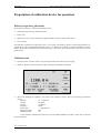
Calibrator start
·
Insert the power cord into socket in rear panel and connect the cord into power supply.
·
Switch on the device at the rear panel. After switching on illuminates the display.
·
After tests finishing the calibrator sets itself to the reference position. That is the following parameters
setting:
Function
W – real power
Voltage
80.000 V
Current
5.00000 A
Frequency
50 Hz
Power factor
+ 1.00 (phase 0°)
Output terminals
OFF
Displaying mode
3f
At the calibrator manufacturing there was set up the address GPIB on the value 2. This value is valid till
the user changes it.
User's manual v14
3
Three-phase Power/Energy Calibrator M-103
MEATEST, s.r.o .
Warm up
The calibrator is functional after its switching on and introductory tests run. However specified parameters is
reached only after worming up for time about 30 minutes. In course of this time calibration of the device cannot
be done. At attempt to make a calibration the device displays error.
Fuse exchange
The cut-out fuse of a calibrator is placed in power supply module in the rear panel together with the spare fuse.
The replacement procedure is following:
·
Take out the power supply cord from the device.
·
Insert edge of a screwdriver into slot of slip-in part of the cord entry and with slight moving pull it out.
·
The inserted fuse is placed in rear part of socket, the spare fuse in front space. If is the connected fuse
defective, take it out and replace by the spare one.
Safety provisions
The device is designed in the safety class I by the EN 61010-1. At the device are applied requirements of the
standard including the supplement A2.
Design and use of specified types of parts ensure safety level.
The manufacturer does not guarantee for damages being consequence of intervention into the device construction
or by part replacement another than original type part.
Used warning symbols
Notice; reference on original documentation
Notice on danger of injury by electric voltage.
Attention, high voltage
4
User's manual v14
MEATEST, s.r.o.
Three-phase calibrator of power output and energy M -103
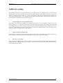
Description
Front panel
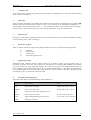
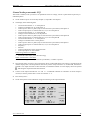
The calibrator front panel incorporates LCD display, control keys and output terminals. Control part of the panel
is shown on the following figure.
1
2
3
8
7
1
4
5,6
9
7
10
7
LCD display
The display serves for calibrator state showing. Detailed description of the display arrangement is in the next
text.
2
Display keys
The four upper keys are keys of the display and have variable meaning. Their function is always marked on the
display. They are used usually for calling up the MENU, decimal changes of the set up values, stepping and
similar.
The last key in column marked MODE/LOCAL is aimed for service functions calling up. In the mode of control
through the GPIB bus, the calibrator can be transferred to the local mode control from the front panel by this key
pressing down.
User's manual v14
5
Three-phase Power/Energy Calibrator M-103
3
MEATEST, s.r.o .
Numeric keyboard
The keyboard contains keys for cursor on the display setting into required position (<, >). The cursor may be
moved right or left. The keys marked Ù, Ú enable number stepping on the cursor position up or down. The
stepping is with transfer to higher (lower) order.
Another keys create numeric keyboard with decimal point and the confirmation key ENTER. The keys in the
upper row serve for number cancelling (C), exponent (E) entering, sign (+/-) and cancellation of requirement on
number entering (CANCEL).
4
Function keys
The function keys serve for direct selection of the calibrator functions. The first group consist of keys OUPUT A,
OUTPUT B, OUTPUT C and 3f, by which may be switched the two basic modes of the device. By pressing
down of the key 3f the calibrator enters into the state, in which are all 3 phases set in the same way. After
pressing the keys OUTPUT A, B or C the calibrator overpasses into a state enabling setting up of different values
of voltage, current and phases for individual outputs A, B, C.
Other keys serve for control of the output terminals. The key ALL/SIMPLE switches over two modes of the
output terminals. In the mode ALL all terminals are switched on and off simultaneously by means of keys ON-C
and OFF-C. In the mode Simple are terminals switched on individually by the keys ON-A, ON-B, ON-C and
switched off by OFF-A, OFF-B and OFF-C. By the key PRG may be programmed, which terminals in the mode
ALL will be controlled simultaneously. After the key PRG pressing down may be by the keys Output A, B, C
connected (disconnected) individual terminals to the common control. By repeated pressing is the terminal in turn
connected and disconnected. By the key PRG pressing down is the mode of terminals programming finished.
5
Output terminals indication
The LED diodes indicate, if individual terminals are connected or disconnected.
6
Power supply switch
It serves for calibrator switching on and off. Because after switching on there are running internal tests, the
calibrator does not react several seconds on commands from the keyboard.
7
Output terminals
To the output terminals is connected the output signal of the calibrator. Each phase has individual terminal,
marked as A, B and C. Currents are connected to the terminals marked +I / -I, voltages are connected to the
terminals Hi / Lo. The calibrator enables four-terminal connection of voltage ranges. If there is selected the fourterminal connection, the terminals sHi / sLo are the sensing terminals.
WARNING
The terminals sHi and sLo are sensing ones, not power terminals and
current cannot be withdrawn from them. Sensing terminals loading may
result in calibrator damage.
6
User's manual v14
MEATEST, s.r.o.
Three-phase calibrator of power output and energy M -103
The terminal GND is connected to the frame of the calibrator and to the power supply ground. In the service
MENU of the calibrator it may be set up grounding of the output terminals on or off. The grounding is done by
connection of the terminals Lo and GND by means of relay. The measuring circuit connection with grounding on
is suitable for most calibrations, when the calibrated object (wattmeter) is floated.
WARNING
If the terminal GND is interconnected with the terminals Lo, sLo, -I, it is
inadmissible to withdraw power from the terminals GND / Hi, GND / +I or
the GND / sHi. These terminals loading may result in calibrator damage.
8
DC multimeter input
This terminal serves as DC voltmeter with range of +/- 13 V, or as a DC ammeter with range of +/- 25 mA
respectively. It is determined for checking of the output signal of the power transducers. The positive terminal is
marked Re1, the negative Re2. The input terminals are not grounded. In the system menu of the calibrator it can
be selected voltage or current mode or the input terminals can be disconnected.
9
Impulse counting input
This input terminal acts as impulse counter. The frequency range of impulses is from 0 to 20 Hz. Maximal
allowed voltage is +/- 50V. Positive impulses or close event of external relay can be measured. This function is
aimed for testing of those electrometers, which are equipped with impulse output. Positive terminal is marked
Re1, negative terminal is Re2. Input terminals are not grounded. In service MENU can be chosen mode of
impulse counting or input terminals can be disconnected. Both impulse counting and DC voltage/current by
internal multimeter measuring can be used at the same time. Every impulse measured on input terminals is
indicated by LED diode.
10 AC voltage 24V
On this terminal is brought AC voltage 24V. It may be used for transducer power supplying. The terminals are
secured by fuse T1L250, placed on real panel of the device.
User's manual v14
7
Three-phase Power/Energy Calibrator M-103
MEATEST, s.r.o .
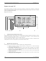
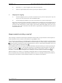
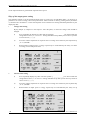
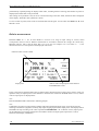
Display in the mode 3f
All information of the calibrator, as parameters of signal, error messages, and service information are projected
on the LCD display. The display is divided into several information fields. Meaning of some fields depends on
mode, in which the calibrator is. After switching on the device is in mode 3f, when voltage, current and power
factor are set for all three phases together. The mode 111f serves for individual setting of these parameters in
each phase.
Display in the mode 3f
1 2 345 6
1.
7
8
Analogue input
In the line, value measured in the analogue input A between terminals Re1 and Re2 is shown. The input can
measure DC voltage in range of +/- 13 V, DC current in range of +/- 25 mA or may be disconnected. The shown
value may be expressed either absolutely (V, mA) or as relative value (%).
2.
Information line
In the line there are shown information of the calibrator, relating to its state. Among them belong:
a)
b)
c)
d)
e)
8
Indication of dangerous voltage on the output terminals by alert arrow. It is shown when output
voltage setting is higher than 100 V.
Indication of connected and disconnected terminals. Simultaneously, the relevant LED is lit on
the control panel.
Error messages of the calibrator. Message is shown if there comes to attempt to set up irregular
state of the device, or when the calibrator analogue circuits are overloaded or if there comes to
error at the device control through the GPIB bus.
Information about remote/local control of the device. In the mode of remote control message
REM is shown on the left side.
Information about four-terminal connection of the voltage output. In the mode of remote
sensing (4W) sign 4W is shown on the right side.
User's manual v14
MEATEST, s.r.o.
3.
Three-phase calibrator of power output and energy M -103
Auxiliary value
In the energy mode, value of energy and energy dose duration is displayed here. In the power mode measured
value on input A is displayed.
4.
Main value
In the line power generated by the calibrator with introduction of relevant unit is displayed. By two symbols ▲ ▼
mutually opposite is indicated active position of cursor. Cursor position can be controlled by pushbuttons <, >
and setting of value on each position by keys Ù, Ú can be achieved. If there is active function „Power stepping“,
in the line there is shown actual power value in percentage, referenced to the power nominal value.
5.
Indication line
Pressed keys of the numeric keyboard are shown here, if the main value is set from numeric keyboard. It enables
to check value of power, which is setting up.
6.
Parameters of signal
There are written main data of signal on the output terminals in two lines. Among them belong especially:
a)
b)
c)
d)
7.
Frequency
Current value
Voltage value
Power factor (phase) value
Supplementary data
Information about calibrator function, output terminal set up mode, accuracy of the generated power in
percentage are shown in this line. Device function is switched over by the display button MODE. The function
are cyclic switched over in the following sequence: W-VA-VAr-Ws-VAs-VAsr. The output terminals mode can
be set SIMPLE, when each terminal group (A, B, C) is controlled individually, or ALL when all terminal group
are controlled together by means of the keys ON-C and OFF-C. In ALL mode, it is possible to program the type
of terminals (A, B, C), to which the control will relate.
8.
Description of the display keys
In the table below there is described meaning of four display keys.
Symbol
Key function
Note
UP
Power value increasing
the step may be set 1 – 50 %
DOWN
Power value decreasing
the step may be set 1 – 50 %
sel
Selection of value type, which may be set
FUNC
Device functions setting
W-VA-Var-Ws-Vas-VAsr
units
Value setting finishing by unit selection
(LA = 0-180°, LE = 180-360°)
EXIT
Finishing of operation
User's manual v14
9
Three-phase Power/Energy Calibrator M-103
MEATEST, s.r.o .
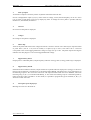
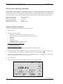
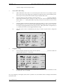
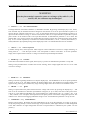
Display in the mode 111f
After calibrator switching to the mode 111f (press key OUTPUT A, OUTPUT B or OUTPUT C), display has
different arrangement. In three columns there are displayed information about all outputs of the device. All these
values can be independently changed.
Display in the mode 111f
1 2 3 4 5 67
1.
8
9
Analogue input of DC multimeter/pulse counter
In DC multimeter mode, value measured on the analogue input A between terminals Re1 and Re2 is shown.
Calibrator can measure DC voltage in range of +/- 13 V or DC current in range of +/- 25 mA. The shown value
may be expressed either absolutely (V, mA) or as relative value (%).
In pulse counting mode, number of pulses on input B between terminals Re1 and Re2 is displayed. Pulse
counting function is active in energy mode only, when output terminals are ON.
2.
Information line in the mode 111f
In the line there are shown information, relating to calibrator state. Among them belong:
a)
Indication of dangerous voltage on output terminals by warning arrow. It is shown when output
voltage setting is higher than 100 V.
b) Error messages of the calibrator. Message is shown if there comes to attempt to set up irregular
state of the device, or when the calibrator analogue circuits are overloaded or if there comes to error
at the device control through the GPIB bus.
c) Information about remote/local control of the device. In the mode of remote control message REM
is shown on the left side.
d) Information about four-terminal connection of the voltage output. In the mode of remote sensing
(4W) sign 4W is shown on the right side.
10
User's manual v14
MEATEST, s.r.o.
3.
Three-phase calibrator of power output and energy M -103
State of outputs
Actual state of outputs is shown by means of symbols switched on/off in the line.
Inverse is displayed the output (A, B, C), which values of voltage, current, PF and frequency can be set. Active
type of value in each phase can be set by display key SEL. To change the active phase is possible with keys
OUTPUT A, OUTPUT B, OUTPUT C.
4.
Currents
Set current in each phase is displayed.
5.
Voltages
Set voltage in each phase is displayed.
6.
Phase shift
Value of the phase shift between the voltage and current is shown in the line. The value may be expressed either
as power factor (1.00 to – 1.00, LAG or LEAD), or as phase (0 up to 360°). The value 1.00 to -1.00 LAG
corresponds to the current lagging behind the voltage in range of 0 up to 180°. The phase expressed in degrees
indicates how many degrees is the current logged behind the voltage.
7.
Supplementary data I
Output power in individual phases, output frequency and time of energy dose (in energy mode only) is displayed.
8.
Supplementary data II
Information about calibrator function, output terminal set up mode and total output power (energy) are shown in
this line. Device function is switched over by the display button MODE. The function are cyclic switched over in
the following sequence: W-VA-VAr-Ws-VAs-VAsr. The output terminals mode can be set SIMPLE, when each
terminal group (A, B, C) is controlled individually, or ALL when all terminal group are controlled together by
means of the keys ON-C and OFF-C. In ALL mode, it is possible to program the type of terminals (A, B, C), to
which the control will relate.
9.
Description of the display keys
Meanings are same as in the mode 3f.
User's manual v14
11
Three-phase Power/Energy Calibrator M-103
MEATEST, s.r.o .
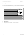
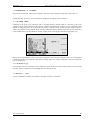
Rear panel
Rear panel of the calibrator integrates ventilation holes, power cord entry with fuses, connector IEEE 488 for
connection on GPIB bus and nameplate with manufacturing number.
1
2
3
4
5
Holes of forced ventilation.
Power supply module.
Connector of GPIB bus.
Fuse enclosure 24V AC (Re1, Re2 output C – power supply for transducers).
Nameplate.
12
User's manual v14
MEATEST, s.r.o.
Three-phase calibrator of power output and energy M -103
Calibrator setting
After calibrator switching on and the introduction test running through, the calibrator comes over to referential
setting, which is function of real power in mode 3f (all phases have the same setting). There are set up current
value 5A, voltage 80V, power factor +1 (phase 0°), frequency 50 Hz and the output terminals switched off.
Actual output terminal mode is ALL with all output terminals controlled together. The state of the calibrator can
be changed by the following ways from the front panel:
1.
Function change by some of the functions keys
By pressing some of the keys OUTPUT A, OUTPUT B, OUTPUT C or 3f, the device switches over to the
required mode (111f - 3f) with referential or the last selected setting of parameters. By pushing of keys PRG and
ALL/SIMPLE can be set required mode of output terminals switching on/off. By pressing of display key FUNC
can be set required function (real power [W], apparent power [VA], reactance power [VAr], real energy [Ws],
apparent energy [VAs] and reactance energy [VArs] ).
2.
Output terminals switching on/off
Output power can be switched on and off by pressing keys ON-x/OFF-x. In the mode ALL is active only the keys
ON-C and OFF-C. Pushing of another keys ON-x/OFF-x cause error message of the calibrator.
3.
Enter into service menu
After pressing key MODE, menu of service functions is shown on the display. Repeated pressing of the key
MODE will cause switching among menu SETUP 1, SETUP 2 and reference position. More detail information
are described in latter chapters.
User's manual v14
13
Three-phase Power/Energy Calibrator M-103
MEATEST, s.r.o .
Output power value setting
The required output power can be set up directly only in mode 3f. Changing of output power is done only by
changing of output current. When power on display is set to another value, appropriate output current is
calculated and displayed on the screen. Output voltage and phase shift remains unchanged. In mode 111f, it is not
possible to set output power directly. Output power is always calculated from output voltage, current and power
factor.
In mode 3f may be set required value of output power in three ways:
1.
2.
Value setting from the numeric keyboard
a)
Select required value on the numeric keyboard . After first digit pressing, unit of set up
function is shown. In the control line are shown symbols [ _ _ _ _ _ _ _ ].
b)
After value writing (simultaneously is shown value in the control line), press the display key
with required unit (on the figure above W) or press key ENTER. When key ENTER is used,
required value of power must be in basic unit, W, VA etc.
c)
Written value is overwritten to the main value and the control line disappears.
Value setting by cursor keys
a)
14
Press the key < or >. On the display are shown the cursor marks, pointing on the active digit.
User's manual v14
MEATEST, s.r.o.
3.
Three-phase calibrator of power output and energy M -103
b)
By the keys Ù a Ú may be stepped value on the cursor's position.
c)
Return to original display may be done by pressing the display key EXIT.
Output power stepping
a)
Press the display key UP, if you want to increase the set up value of output power. Step size
may be set in the system menu in the item POWER STEP.
b)
Press the display key DOWN, if you want to decrease the set up value of output power.
Step size is expressed in percent and relates to nominal value of a output power. This nominal value of
output power is not changed by a step execution. However you can change value of nominal power by
new power value setting (power, current, voltage or power factor). When the output power is not set on
the nominal value, there is beside the main data shown a supplementary information haw many percent
of nominal value is set.
Output terminals switching on and off
After switching on calibrator has the output terminals disconnected. Way of output terminals control depends on
mode of terminals control, in which is the calibrator set up (SIMPLE / ALL).
In the mode ALL all terminals are controlled together. Output terminals switching on is done by pressing the key
„ON-C“. After terminals switching, the red indication of relevant output is lit. On the display is displayed symbol
. Output terminals switching off is done by pressing the key „OFF-C“. Red indication disappears and on the
display is shown symbol of switched terminals .
In the SIMPLE mode can be each output controlled individually. Terminals switching on is done by pressing the
keys ON-A, ON-B or the ON-C. After terminals switching on, red indication of relevant output is lit and on the
display is shown symbol . Output terminals switching off is done by pressing the key „OFF-A“, „OFF-B“ or
the „OFF-C“. The red indication disappears and on the display is shown symbol of switched terminals .
When the calibrator is in mode 3f , on the display is displayed symbol of connected terminals always , even if
there is switched on only one terminal. Which of the terminals A, B, C are switched on indicates the red LED on
the front panel. In the mode 111f has individual terminals its own indication on the display.
User's manual v14
15
Three-phase Power/Energy Calibrator M-103
MEATEST, s.r.o .
Electric power and energy generation
The three-phase calibrator enables to generate precise value of AC power and electric energy, voltage on the
output terminals Hi - Lo and current on the output terminals +I - -I. The voltage terminals Lo of all three phases
are galvanic connected. In the system menu of the device can be these terminals grounded (recommended) or let
them as floating ones. In such case maximum permissible voltage on these terminals against ground is 20Vrms.
Range of power setting:
Range of voltage setting:
Range of current setting:
Range of phase setting:
Range of frequency setting:
1.8 VA to 7200 VA
6 V to 240 V
0.1 A to 10 A
0 to 360°
40 Hz to 400 Hz
Control in the power mode 3f
This mode is suitable for all three phases setting in the same way.
·
Press the key 3f.
·
Display shows following data:
* Main data of set output power in selected unit W, VA, VAr
* Value of power factor or phase (may be selected in system menu)
* Frequency
* Set current
* Set voltage
* Calibrator function
* Configuration of output terminals control
In the energy functions in addition to it
* Time of energy dose
* Quantity of sent energy
When internal meter is activated
* Value of voltage or current, measured by multimeter, or number of pulses
·
Set up required main value of output power either from the numeric keyboard or by cursor calling by keys <,
>. Output terminals are disconnected, in the display information line is displayed sign .
·
Connect to the output terminals Hi - Lo and +I - -I calibrated wattmeter or transducer. If current output is
not used, it must be perform short-circuit on terminals +I - -I.
·
Press the key ON-x.
·
On the front panel lights indication of signal connection to the output terminals.
16
User's manual v14
MEATEST, s.r.o.
Three-phase calibrator of power output and energy M -103
On the output terminals is generated required power.
Calibrator functions
The calibrator enables three basic modifications of electric power:
·
·
·
Real power (W)
Apparent power (VA)
Reactive power (VAr)
Change of function is done by repeated pressing of display key FUNC. Actual function is displayed in line of
supplementary data in form FUNCTION x, where “x”is symbol of function. Main value of output power and its
unit is changed simultaneously.
Ways of power setting up
The calibrator enables to set up generated output power in several ways.
1.
2.
Main power data setting
a)
The main data can be set either directly from the numeric keyboard, or by using the cursor's
keys <, >, Ù, Ú, or by stepping with display keys UP, DOWN.
b)
Output power change is done by change of current in this case.
Voltage data setting
a)
The main power value can be set by voltage value changing.
b)
Press repeatedly the display key SEL until the symbols [ _ _ _ _ _ _ _ ] are shown under the
voltage value in form of „U = xxx.xx V“.
c)
From the numeric keyboard set required value of voltage and confirm it by pressing the
keyboard key „V“ or „ENTER“.
d)
The output power value is recalculated by the newly set up voltage value, current and power
factor setting.
User's manual v14
17
Three-phase Power/Energy Calibrator M-103
3.
MEATEST, s.r.o .
Current data setting
4.
a)
The main data can be set by current value change.
b)
Press repeatedly the display key „sel“ until the symbols [ _ _ _ _ _ _ _ ] are shown under the
current value in form of „I = xx.xxxxx A“.
c)
From the numeric keyboard set required value of current and confirm it by pressing the
keyboard key „A“ or „ENTER“.
d)
The output power value is recalculated by the newly set up voltage value, current and power
factor setting.
Power factor value setting
18
a)
When indicated in units of W or VAr, main data can be changed by power factor value setting.
Power factor value change has not influence on value of the apparent power. Instead of power
factor may be selected in system menu phase shift in "°".
b)
Press repeatedly the display key SEL until the symbols [ _ _ _ _ _ _ _ ] are shown under the
power factor value in form of „PF = x.xx LA“ or „PF = x.xx LE“ respectively. In case of phase
shift setting is the indication „DEG = x °“.
c)
From the numeric keyboard set required value of power factor (+1.00 to -1.00) and confirm by
display key „LA“, if you want current being lagged voltage (0 up to 180°) or „LE“, if you want
voltage being lagged current (180 up to 360°). When phase shift is setting directly in "°", it
shows how much is current lagged behind the voltage.
d)
Output power value is recalculated by the newly set value of power factor, voltage and current.
User's manual v14
MEATEST, s.r.o.
5.
Three-phase calibrator of power output and energy M -103
Frequency setting
a)
Press repeatedly display key SEL until the symbols [
about frequency in form „f = xxx.xx Hz“.
_ _ _ _ _ _ _ ] are shown under data
b)
From the numeric keyboard can be set required value of frequency. Pressing of the display key
„Hz "or the „ENTER" is done value confirmation.
If newly set frequency value is higher (lower) than is frequency range, the calibrator shows on the display
maximum (minimum) value.
When frequency is changed, calibrator automatically disconnects the output terminals. To their reconnection is
necessary to press the key ON-x.
6.
Energy setting
Into the energy mode it can be passed by repeated pressing of the display key FUNC. In field of
accessory data is shown time in seconds and energy, supplied after pressing the key ON to the output
terminals. Range of time setting is from 10 s up to 1999 s.
Energy value can be set in two ways:
a)
Time setting
·
After energy function selection press repeatedly the display key SEL until the symbols
[ _ _ _ _ _ _ _ ] are shown under the time data TIME [s].
·
From the numeric keyboard set required value of time and confirm by the display key „s“.
·
Energy value is recalculated by newly set time value.
b)
Direct energy setting
·
After energy function selection press repeatedly the display key SEL until the symbols
[ _ _ _ _ _ _ _ ] are shown under the time data ENERGY [Ws].
·
From the numeric keyboard set required value of energy in Ws or kWs and confirm by the
display key „Ws“ or „kWs“.
·
Time value is recalculated by newly set energy value.
User's manual v14
19
Three-phase Power/Energy Calibrator M-103
20
MEATEST, s.r.o .
User's manual v14
MEATEST, s.r.o.
Three-phase calibrator of power output and energy M -103
Control in the power mode 111f
This mode is suitable, when you want to set up different values of voltage, current or phase shifts respectively in
individual phases.
·
On the calibrator press one of the keys Output A, Output B or the Output C.
·
The display shows following data:
* Current from terminals +I - -I of the phase A
* Voltage on terminals Hi -Lo of the phase A
* Value of power factor or phase (may be selected in the system menu) of the phase A
* Value of output power in selected units W, VA, VAr of the phase A
* Current from terminals +I - -I of the phase B
* Voltage on the terminals Hi -Lo of the phase B
* Value of power factor or phase (may be selected in the system menu) of the phase B
* Value of output power in selected units W, VA, VAr of the phase B
* Current from terminals +I - -I of the phase C
* Voltage on terminals Hi -Lo of the phase C
* Value of power factor or phase (may be selected in the system menu) of the phase C
* Value of output power in selected units W, VA, VAr of the phase C
* Frequency
* Function
* Control configuration of the output terminals
* Total output power on all terminals
In the energy function in addition
* Time of energy dose
* Instead the total output power the total energy
When internal meter is activated
* Value of voltage or current, measured by multimeter, or number of pulses
·
Set required values of voltage, current and power factor in individual phases. The setting is possible from the
numeric display after relevant parameter selection by means of keys OUTPUT A, OUTPUT B, OUTPUT C
and SEL. The output terminals are disconnected, at individual terminals is on the display shown the symbol
, indicating the output terminals disconnection.
·
Connect to the output terminals Hi - Lo and +I - -I calibrated wattmeter or transducer. If current output is
not used, it must be perform short-circuit on terminals +I - -I.
·
Press the key ON-x.
·
On the front panel is lit the indication of signal connecting to the output terminals.
User's manual v14
21
Three-phase Power/Energy Calibrator M-103
MEATEST, s.r.o .
On the output terminals is generated the required electric power.
Ways of the output power setting
The calibrator enables to set the generated output power in several ways. In individual phases (A, B and C) is
possible to set value of voltage, current and power factor. Phase selection is done by pressing the key OUTPUT
A, OUTPUT B or OUTPUT C. In the selected phase can be switched over among individual parameters by the
display key SEL.
1.
Voltage value setting
By key Output A, Output B or the Output C select the phase, in which the voltage value should be
changed.
2.
a)
Press repeatedly the display key SEL until the symbols [ _ _ _ _ _ _ _ ] are shown under the
voltage data in form „U = xxx.xx V“. Among individual set up values you can move by means
of cursor arrows (^,Ú,<,>).
b)
From the numeric keyboard set required value of voltage and confirm by the keyboard key
„V“ or „ENTER“.
c)
Relevant data of output power or energy respectively are recalculated by the newly set values
of voltage, current and power factor.
Current value setting
22
a)
Press repeatedly display key SEL until the symbols [ _ _ _ _ _ _ _ ] are shown under the
voltage data in form „I = xx.xxxx A“. Among individual set up data you can move by means of
cursor arrows (^,Ú,<,>).
b)
From the numeric keyboard set required value of voltage and confirm by the keyboard key
„A“ or „ENTER“.
c)
Relevant data of output power or energy respectively are recalculated by the newly set up
User's manual v14
MEATEST, s.r.o.
Three-phase calibrator of power output and energy M -103
values of voltage, current and power factor.
3.
4.
Power factor data setting
a)
When indicated in units of W or VAr, the main power value can be set by change of power
factor. Power factor value change has not influence on apparent power value. Instead the power
factor may be in the system menu selected setting of the phase shift in the °.
b)
Press the display key SEL repeatedly, until the symbols [ _ _ _ _ _ _ _ ] are shown under the
power factor in form of „PF = x.xx LA“ or „PF = x.xx LE“. In case of phase shift setting is
shown „DEG = x °“. Among individual set up data you may move by means of cursor arrows
(^,Ú,<,>).
c)
From the numeric keyboard set required value of the power factor (+1.00 to -1.00) and confirm
by the display key „LA“ for the current being lagged behind voltage (0 up to 180°) or the „LE“
for voltage being lagged behind current (180 up to 360°). When phase shift is setting directly in
"°", it shows how much is current lagged behind the voltage.
d)
The main power value is recalculated by the newly set values of power factor, voltage and
current.
Frequency setting
a)
Press repeatedly the display key SEL until the symbols [ _ _ _ _ _ _ _ ] are shown under the
frequency data in form „f = xxx.xx Hz“.
b)
From the numeric keyboard can be set required value of frequency. Value confirmation is done
by display key „Hz“ or „ENTER“.
If is set up frequency value higher (lower) than is possible to set, the calibrator shows on display the maximum
(minimum) value.
User's manual v14
23
Three-phase Power/Energy Calibrator M-103
MEATEST, s.r.o .
When frequency is changed, the device disconnects automatically the output terminals. For their reconnection is
necessary to press the key ON-x.
5.
Energy setting
Into the energy mode may be entered by repeated pressing of the display key FUNC. In the field of
accessory data is shown time in seconds and energy, supplied after ON pressing to the output terminals
at actual setting of voltage, current and power factor. Range of time setting is 10 s up to 1999 s.
Energy value may be set up in two ways:
a)
Time setting
·
Press repeatedly the display key „sel“ until the symbols [ _ _ _ _ _ _ _ ] are shown under the
time data „TIME [s]“.
·
24
From the numeric keyboard set up required value of time and confirm by the display key „s“
pressing.
·
The energy data is recalculated by the newly set up time value.
b)
Direct energy setting
·
After energy mode selection press repeatedly display key SEL until the symbols [ _ _ _ _ _ _ _
] are shown under the time data „ENERGY [Ws]“.
·
From the numeric keyboard set required value of energy in Ws or kWs and confirm it by the
display key „Ws“ or „kWs“.
User's manual v14
MEATEST, s.r.o.
·
Three-phase calibrator of power output and energy M -103
Time value is recalculated by newly set up value of energy.
CAUTION
When calibrated devices with galvanic separated current and voltage circuits inputs, it is necessary to
switch on the calibrator M-103 the function GND to position ON. This will cause galvanic connection
the terminals Lo a -I with the terminal GND in the calibrator.
When calibrated device has the voltage and current inputs galvanic connected, it is necessary to switch
on the calibrator M-103 the function GND to position OFF. This will cause disconnection the terminals
Lo and -I from the terminal GND in the calibrator.
Note: At simultaneous connection of terminals Lo and -I on the calibrator and on the calibrated device
too, the voltage drops on current cables can damage the special relays, which connect the
terminals Lo and -I with the terminal GND.
Built-in meter
Calibrator is equipped with build-in meter. This meter enables to measure value of output signal of various
electric power transducers which have analogue or pulse output. Measuring of output signal devices under test
and generating of calibrated output power are simultaneous, both function can be used at the same time. Basic
parameters of internal meter are following:
Function:
Range of current:
Range of voltage:
Range of pulse counting:
DC voltage, DC current, pulse counting
0 to 25 mA
0 to 13 V
0 to 65 535
When build-in meter is used for measuring of DC current or DC voltage , input signal have to be connected to the
input terminals Re1 (H) and Re2 (L) in section A of the calibrator. When it is used for pulse counting, input
signal have to be connected to the input terminals Re1 (H) and Re2 (L) in section B of the calibrator.
Common terminal L of the multimeter (Re1) is galvanically isolated from the output terminals L.
Setting of meter
Required function of meter can be set in menu SETUP 1, item INPUT A, B.. xx. By pushing the display buttons,
switching among functions 10 V, 20mA, CNT and OFF can be performed. When parameter OFF is chosen,
meter is switched off. This parameter is also pre-set by manufacturer.
By repeated pushing the display button 10 V, switching among absolute reading 10 V (absolute measured value
is displayed), relative reading 10 V% (relative measured value is displayed) and status OFF can be performed.
By repeated pushing the display button 20 mA, switching among absolute reading 20 mA (absolute measured
value is displayed), relative reading 20 mA% (relative measured value is displayed) and status OFF can be
User's manual v14
25
Three-phase Power/Energy Calibrator M-103
MEATEST, s.r.o .
performed. By repeated pushing the display button CNT, switching between counting (total number of pulses is
displayed) and status OFF can be performed.
After setting one of parameter 10V, 20 mA or CNT and returning to the basic mode, measured value is displayed
on the display. Ahead the value symbol M is shown.
To reset counter of pulses, meter must be switched OFF and ON again. Use the same item INPUT A, B.. xx in
SETUP 1 menu.
Relative measurement
Parameter 100% A = ... xx in menu SETUP 1 involves to set range of input voltage or current, which
corresponds to the level 100 %. Relative measurement is accessible in function DC voltage, DC current only.
Maximal value for 100 % must be lower than 13 V or 25 mA. For example, if it is set 100% A = ... 5 mA
measured current 5 mA corresponds to the displayed value 100%.
measured value in relative mode
output power
relative value of output power when function
POWER STEP is used
Upper value with pre-displayed letter M is by build-in meter measured value in relative form. Value in lower row
represents really set output power of the calibrator in absolute form. If function POWER STEP is set on, relative
value of output power is displayed here.
Note
Function POWER STEP is described in following chapter.
Note
Combination of relative expressed meter readings and relative displayed output power can be easily used for
checking of transducers (regulators) linearity. By simple stepping up and down output power with display buttons
UP/DOWN in steps according to the value in parameter POWER STEP.... xx in SETUP 1 menu, output power
can be changed in pre-set steps and response of transducer under test output signal expressed in % can be
followed on the display immediately.
26
User's manual v14
MEATEST, s.r.o.
Three-phase calibrator of power output and energy M -103
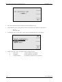
Service functions menu
The calibrator enables to set and display some other parameters. The setting is done in the menu of service
functions. This menu can be called by pressing the key MODE. When key MODE is pressed, the calibrator
disconnects output terminals, if they are connected. Display shows offer of service functions SETUP 1:
By the keys Ú, Ù it can be stepped in menu. Descriptions of display keys simultaneously change depending on
active line of menu (is shown in inverse way). It is shown, how can be the relevant parameter set up. After
parameters setting can be passed to the service functions SETUP 2 by the display keys „EXIT“ or „MODE“. If
key „MODE“ is repeated pressed, the calibrator returns back to its basic mode. New parameters setting remains
preserved even after the calibrator is switched off. Exception is setting of four-terminals connection of voltage
output. This is always set up in the state 2W after calibrator switching on. The menu contains following items:
Menu of service functions SETUP 1
1.
GPIB ........ xx UP/DOWN
It shows valid address of the calibrator when it is controlled through GPIB bus. By stepping with display keys
„UP“ and „DOWN“ it can be set up any permitted address in range from 00 to 30. At manufacturer GPIB address
is set up on value 02.
2.
GND .........xx ON/OFF
Connection of terminals Lo, sLo, -I to the terminal GND. It practically represents grounding of the Lo terminals
of the calibrator. By display keys it can be changed between connection and disconnection. At manufacturer it is
set up to position ON, the output terminals are grounded.
3.
SENSE........xx 4W/2W
It is control of the four-terminal connection of voltage output. By pressing the display keys 4W/2W may be
switched over between the four-terminal (4W) and two-terminal (2W) connection. After calibrator switching on,
the parameter is set up to position 2W, two-terminal connection. Use of four-terminal connection is
recommended in specified cases only.
User's manual v14
27
Three-phase Power/Energy Calibrator M-103
MEATEST, s.r.o .
WARNING
If at the four-terminal connection comes to exchange of the cables Lo, sLo
and Hi, sHi, the calibrator may be damaged!
4.
INPUT A … .. xx
10 V/20mA/CNT/OFF
It changes function of terminals OUTPUT A, marked Re1 and Re2. By pressing of the display keys 10 V, 20mA,
CNT and OFF may be terminal's functions changed. In the function 10 V serves input terminals on phase A as
input of the DC voltmeter with range of +/- 10 V. In the function 20mA serves input terminals on phase A as
input of the DC ammeter of range +/- 20mA. In the function CNT serves input terminals on phase B as input of
pulse counter. In the function OFF is the input disconnected. At manufacturer parameter is set to OFF. The
terminal Re1 is for positive polarity, the terminal Re2 for negative polarity. By repeated pressing of the display
keys 10 V or 20 mA respectively is switched over between the absolute (+/-10 V, +/-20 mA) and relative (+/100%) indication. By repeated pressing of the display keys CNT it is switched between CNT On and OFF.
5.
100% A = ... xx
numeric keyboard
It enables setting value, which represent 100% range for relative indication of current or voltage measuring. At
setting 100% A = ... 5 mA the input current 5 mA corresponds to relative value 100%. To set this parameter
simply enter required value of current or voltage via numeric keyboard and press ENTER.
6.
KEYB.beep .... xx
ON/OFF
It switches on and off the acoustic signal, when any key is pressed. At manufacturer parameter is set up ON.
Setting of this parameter does not affect the acoustic warning, when voltage higher than 100 V is set or when
occur error message.
7.
KEYB.vol. .... xx
UP/DOWN
Setting of acoustic signalling loudness level. By the display keys UP and DOWN it can be set up the parameter
in range of 00 up to 31. The higher number, the higher loudness level. The loudness level setting relates to the
signal of a key pressing (if is switched on), usage of voltage higher than 100 V and error of calibrator control.
8.
PHASE … … . xx
°/COS
Setting of representation the phase shift between the voltage and current. By pressing the display keys ° and
COS it can be switched over between representation in degrees (0° up to 360°) and value of the power factor
(1.00 up to -1.00). Between individual ways of representation are valid relations 1.00 = 0°, 0.00LA = 90°, -1.00
= 180°, 0.00LE = 270°. The phase shift expresses current phase position towards the voltage phase position. The
readout of 90° means current lagging behind the voltage of 90°. At manufacturer parameter is set up to COS.
9.
CONTRAST .... xx y UP/DOWN/INV.
Display contrast setting. By display keys UP and DOWN it can be set up the parameter xx in range of 00 up to
63. By the pressing the key it can be inverted type of representation, either light characters on dark background
or the dark characters on light background. Inversion of representation is indicated by the symbol I on the
position y.
28
User's manual v14
MEATEST, s.r.o.
Three-phase calibrator of power output and energy M -103
10. POWER STEP.... xx UP/DOWN
Step size for the function „output power stepping“. Step size can be changed in range from 1 up to 50%. At
manufacturer step is set up to 10%. The function „output power stepping“ runs in mode 3f.
11. CAL.CODE .. 00000
Calibration code setting. The calibration code is five-digit number, through which it is possible to enter into
calibration mode. If the calibration code equals to „00000“, this information is shown in service functions menu
and can be changed by user. New calibration code setting is done directly by writing from the numeric keyboard
and its confirmation by key ENTER. When non-zero calibration code is written and confirmed, this function is
not accessible further. To the calibration mode is possible to enter after proper calibration code setting only.
Purpose of use the calibration code is to prevent a trespasser to intervene into calibration data. It Is recommende d
to make note of the set up calibration code after its setting. Value of a non-zero calibration code can be found out
only at manufacturer.
12. CAL.DATE xx.yyyy
It shows date of the last calibration of the calibrator in form month.year. Value of date cannot be in this menu
recorded. Date of calibration can be changed after new calibration only.
13. DEVICE N. . xxxxx
It shows identification number of a calibrator. Parameter cannot be overwritten.
User's manual v14
29
Three-phase Power/Energy Calibrator M-103
MEATEST, s.r.o .
Menu of service functions SETUP 2
1.
PHASE UA/UB .. xxx
numeric keyboard / CLEAR
This function enables to set phase shift between channel A and channel B. After calibrator switching on, the
phase shift is 120°. To set another value, write from numeric keyboard required phase shift and press ENTER. To
turn back to the default value of 120° is possible anytime by pressing key CLEAR.
2.
PHASE UA/UC .. xxx
numeric keyboard / CLEAR
This function enables to set phase shift between channel A and channel C. After calibrator switching on, the
phase shift is 240°. To set another value, write from numeric keyboard required phase shift and press ENTER. To
turn back to the default value of 240° is possible anytime by pressing key CLEAR.
30
User's manual v14
MEATEST, s.r.o.
Three-phase calibrator of power output and energy M -103
Calibration mode
Calibrator is equipped with calibration procedure, which enables its simple recalibration.
Principles of calibration
Calibration can be perform either as full calibration, i.e. all introduced functions are recalibrated, or partial, i.e.
only selected functions are recalibrated. Total calibration consists of partial calibrations in sequence according
the calibration menu. If there is selected only one item from the calibration menu, e.g. the „VOLTAGE“, it is
necessary to execute calibration of all this function ranges by the algorithm steadily given in the calibrator. If it is
not possible to execute new calibration in all ranges of the selected item (e.g. when there is not disposal absolute
standard of necessary accuracy), it can be let the original calibration data validity.
Calibration method for AC voltages consists in setting of scale factor of each phase (A, B, C), on each voltage
range 80 V and 200 V at frequency 60 Hz.
Calibration method of AC currents consists in setting of scale factor of each phase (A, B, C), on each range 1
A, 5 A a 10 A at frequency 60 Hz.
Calibration method of internal DC multimeter consists in setting of DC offset in points 0.000 V and 0.000 mA
and scale factor in points 10.000 V and 20.000 mA.
Accuracy of the phase shifts among outputs A, B, C and between voltage and current outputs is based on
accuracy and stability of internal crystal oscillator. Because accuracy and stability of this oscillator is more than
one order higher than required accuracy of phase shifts of the calibrator, usually it is not necessary to perform
phase shift recalibration.
Access to the calibration mode
Access to the calibration procedure is protected by calibration code.
·
Press key MODE to access to the service functions menu.
·
Press the display key marked CAL. MODE.
·
If there is done attempt to enter the calibration procedure before 30 minutes period after device switching on,
the device will not allow the make a calibration. In the information line it will be displayed message:
·
If calibrator is switched on for more than 30 minutes, it requires to enter correct calibration code after the
key CAL. MODE pressing.
User's manual v14
31
Three-phase Power/Energy Calibrator M-103
MEATEST, s.r.o .
·
Set correct calibration code and confirm by the key ENTER pressing.
·
If the calibration code is wrong, there is shown error message on the display for time about 3 s:
Err 20
Bad calib. code!
·
If calibration code is correct, there is shown menu of individual functions on the display.
·
By the cursor keys Ù and Ú can be the set active position of cursor:
1.
2.
3.
32
VOLTAGE
CURRENT
ANALOG INPUT
Voltage calibration of all phases
Current calibration of all phases
DC multimeter calibration 10 V and 20 mA
User's manual v14
MEATEST, s.r.o.
Three-phase calibrator of power output and energy M -103
Type of calibration selection
After enter into the calibration menu it may be selected one of the partial calibrations. By the cursor keys Ù and Ú
can be the cursor's active position moved on individual items. After required function setting press the display
key „NEXT“. The display shows the following information (example of voltage calibration VOLTAGE is shown
bellow):
The display is similar for calibration of current ranges. Display keys have following meaning:
WRITE
New calibration value logging into memory, irreversible overwriting of the original
calibration data.
SKIP
Sipping of calibration step, in the memory will remain the original calibration data.
EXIT
Exit from calibration before its finishing. After this key pressing will remain in the
memory actual data and the calibrator returns to the calibration menu. Therefore, it is
not necessary to do new calibration of all ranges, but only e.g. of selected ranges. It
means, that data of those ranges, which we do not want to recalibrate, will be left in
the original form by pressing the key SKIP.
There is shown also value and its necessary accuracy on the display, which must be set up on the standard
multimeter.
New calibration value setting
By the cursor keys Ù, Ú, <, > set up on the display such value, at which the output signal measured by standard
multimeter is equal to the nominal value of calibration point. Press the key „WRITE“. New value is saved in
memory of calibration data. If the key „SKIP“ is pressed, the calibrator ignores new set up value and keeps in the
data memory the original one. After pressing the key „WRITE“ (or „SKIP“) the calibrator passes to the next
calibration point.
Repeat the procedure till all calibration points are not finished in the selected function of calibration. When is
pressed the key „EXIT“ during calibration, the calibrator turns back to the main calibration menu.
User's manual v14
33
Three-phase Power/Energy Calibrator M-103
MEATEST, s.r.o .
End of calibration
The calibration can be finished in the following cases:
·
it was perform complete calibration of the calibrator. After new calibration data setting, calibrator returns
back to the calibration menu,
·
it was done calibration only selected functions. After new calibration data setting, calibrator returns back to
the calibration menu,
·
it was done calibration only on some ranges of one or more functions. After new calibration data setting, the
calibrator returns back to the calibration menu,
·
the calibration was started, but the calibration data has not been changed. After the key „EXIT“ pressing,
the calibrator returns back to the calibration menu.
Finish the calibration by pressing of the display key „EXIT“. After it, service MENU with active line of
calibration date is shown:
UP M
Cyclic stepping of month from 01 up to 12
UP Y
Year of calibration stepping upwards
DO Y
Year of calibration stepping downwards
Set up month and year of new calibration and press the key „EXIT“ to finish the calibration. The calibrator shows
service menu. It can be abandoned by pressing the key „EXIT“. Calibrator setting returns to the state before new
calibration starting. Permissible range of year is since 1900 till 2155.
34
User's manual v14
MEATEST, s.r.o.
Three-phase calibrator of power output and energy M -103
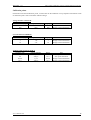
Calibration points
Each function has fixed calibration points, in which must be the calibration set up. Sequence and nominal values
of calibration points come out from the calibrator design.
Voltage function VOLTAGE
Nominal value [V]
80
200
Table ACU
Setting tolerance [V]
10 m
30 m
Range [V]
80
200
Note
Range constant calibration
Range constant calibration
Range [A]
1
5
10
Note
Range constant calibration
Range constant calibration
Range constant calibration
Range
20 mA
10 V
20 mA
10 V
Note
Zero point calibration
Zero point calibration
Range constant calibration
Range constant calibration
Current function CURRENT
Nominal value [A]
1
5
10
Table ACI
Setting tolerance [A]
200 u
1m
3m
Analogue input ANALOG INPUT
Nominal value
0 mA
0V
20 mA
10 V
Table DCUI
User's manual v14
Setting tolerance
1 mA
500 mV
1 mA
500 mV
35
Three-phase Power/Energy Calibrator M-103
MEATEST, s.r.o .
Complete calibration procedure
The following chapter contains description of full calibration.
Necessary equipment
For the calibration are necessary following instruments:
·
81/2-digit multimeter, recommended type HP3458A, Wavetek 1281 or another with accuracy 0.02 % on
VAC
·
Current shunt 100 mW, recommended type Burster 1280 or another with accuracy 0.01% and known
frequency dependency up to 60 Hz.
For parameters checking is recommended counter HP 53181A, distortion meter type HP 8903A, E , oscilloscope
with bandwidth 20 MHz and standard AC wattmeter with accuracy 0.02- 0.05 %.
Calibration procedure
1.
Connect the calibrator and standard multimeter to the power supply and at let them least three hours
switched on in laboratory with temperature 23 ± 1o C.
2.
By the key MODE call up service menu and by the display key CAL. MODE calibration mode.
3.
Set up the calibration mode.
4.
Calibration of voltage ranges.
5.
a)
In the menu of calibration functions select the function VOLTAGE
b)
Execute calibration in all calibration points. Follow the instructions on the display and use
tolerances in the table ACU. The alignment is done by stepping of the main value by the cursor
arrows <, >, Ú, Ù. Confirm new calibration constant by key WRITE.
Calibration of current ranges
36
a)
In the menu of calibration functions select the function CURRENT
b)
Execute calibration in all calibration points. Follow the instructions on the display and use
tolerances in the table ACI. The alignment is done by stepping of the main value by the cursor
arrows <, >, Ú, Ù. Confirm new calibration constant by key WRITE.
c)
It is necessary to use shunt with known frequency dependence up to do 60 Hz on ranges of 5
and 10 A.
User's manual v14
MEATEST, s.r.o.
Three-phase calibrator of power output and energy M -103
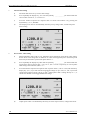
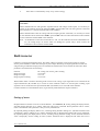
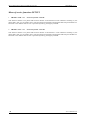
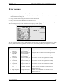
Error messages
If there comes to an error, the device reports its type. The errors can be caused by:
·
wrong control via keyboard, for example by setting of unacceptable mode, value setting outside its range,
output terminal overloading etc.,
·
wrong communication among functional blocks inside the calibrator
·
faulty control through the GPIB bus in remote control mode.
Example of error message, which occurs when calibration before warm up time is passed, is shown on the figure.
The error message is always in the information line in upper part of the display.
The error message consists of error number (follows the ERR signs) and brief description of the error. In the
following table are introduced types of the calibrator errors, their meaning and way of remedy, if it is possible.
Error
No.
1
2
3
4
5
6
7
8
Error description
Meaning
Shooting
Overload I
Output A !
Overload I
Output B !
Overload I
Output C !
Overload U
Output A !
Overload U
Output B !
Overload U
Output C !
High temperature
A!
Voltage overloading of
current terminal A
Voltage overloading of
current terminal B
Voltage overloading of
current terminal C
Current overloading of
voltage terminal A
Current overloading of
voltage terminal B
Current overloading of
voltage terminal C
Too high temperature of
the channel A amplifier
Voltage on load is too high. Decrease loading resistance.
Voltage on load is too high. Decrease loading resistance.
Voltage on load is too high. Decrease loading resistance.
The withdrawn current is too high. Increase loading
resistance.
The withdrawn current is too high. Increase loading
resistance.
The withdrawn current is too high. Increase loading
resistance.
Calibrator is overloaded. Do not switch the output
terminals on at least 10 minutes. Check, if there are
ventilation holes free.
High temperature Too high temperature of Calibrator is overloaded. Do not switch the output
B!
the channel B amplifier terminals on at least 10 minutes. Check, if there are
ventilation holes free.
User's manual v14
37
Three-phase Power/Energy Calibrator M-103
Error
No.
9
10
11
12
20
21
22
30
31
32
36
40
41
42
38
Error description
Meaning
MEATEST, s.r.o .
Shooting
High temperature Too high temperature of Calibrator is overloaded. Do not switch the output
C!
the channel C amplifier terminals on at least 10 minutes. Check, if there are
ventilation holes free.
Interface error !
GPIB communication
Wrong data format on the GPIB bus.
error
Bad command ! Bad command to GPIB Unknown GPIB command.
Bad
GPIB communication
Listener is not connected to the GPIB bus. Check
communication ! error
connection of the system cable.
Bad calib. code ! Bad calibration code
Wrong calibration code, calibration cannot be executed.
Set up correct calibration code.
Time warm up ! Try to calibrate before
Attempt to make calibration before 30 minutes after device
device warm up time
switching on elapse. Let the device switched on for that
expiration
time.
Overload Input A Analogue input of
Decrease voltage (current) connected to analogue input.
!
calibrator overloading
CPU timeout !
Communication error
Device internal error. Switch the device off and switch it
among processors
on after 5 s again. If the error remains unresolved, contact
the manufacturer.
CPU data !
Communication error
Device internal error. Switch the device off and switch it
among processors
on after 5 s again. If the error remains unresolved, contact
the manufacturer.
52<>analog !
Communication error
Device internal error. Switch the device off and switch it
among processors
on after 5 s again. If the error remains unresolved, contact
the manufacturer.
Format
Memory formatting
Non-recoverable failure of calibration data. The device is
EEPROM !
out of specification. Contact the manufacturer.
Value too large! Maximum permissible
Set up value is out of range. Set up correct value.
value exceeded
Value too small! Maximum permissible
Set up value is out of range. Set up correct value.
value exceeded
Bad output
Wrong set up
Output terminals are connected or were disconnected in
mode !
configuration of output way, which is not permitted at the set up configuration.
terminals
Change the configuration of output terminals by means of
keys PRG or All/Simple respectively.
User's manual v14
MEATEST, s.r.o.
Three-phase calibrator of power output and energy M -103
Calibrator maintenance
The three-phase calibrator is sophisticated electronic device with microprocessor control. Power blocks are
cooled by fan. The calibrator has built-in electronic guards, protecting it against damage.
Principles of proper attendance
It is necessary to observe especially following principles:
· Switch the calibrator on and off always by means of the power supply switch, placed on t he front panel.
· Never connect the device to another power supply than 230V / 47 -63Hz.
· Do not admit ventilation limiting through holes on the rear, upper and bottom panels. Do not put on the
calibrator any papers or subjects, which would constrain the ventilation.
· Do not operate the device in dusty surrounding; it is device aimed for laboratory use.
· Do not switch the device on at temperatures out of its operation temperature range.
· Connect the calibrated measuring devices only to relevant output terminals. Against some irregular
connections it is not possible to protect the calibrator sufficiently and efficiently.
· Do not damage the output terminals by inserting of banana pin with diameter bigger than is diameter of
the socket.
· Ground the output terminal Lo (service function GND ON), if DUT is not grounded.
· Do not overload the power circuits of the calibrator by its long time not purposeful switching on, especially
in current range of 10 A and voltage range of 200V.
· If the calibrator is not connected by the original cables supplied with the device, it must be used cables
dimensioned for proper voltage and current. Maximum output voltage may reach 240 V AC on voltage
terminals and output current up to 10 A AC on current terminals.
Calibrator maintenance
The calibrator does not require any special maintenance of the mechanical or electrical parts. Clean the cover and
the LCD display with wool cleaning rag, slightly dipped in spirit.
The calibrator has recommended re-calibration interval 12 months. After this time manufacturer recommends to
re-calibrate calibrator in accredited metrology laboratory.
User's manual v14
39
Three-phase Power/Energy Calibrator M-103
MEATEST, s.r.o .
Action at failure
When operation of calibrator does not seem to be correct (e.g. the display is not lit, the fan does not run), it is
necessary to switch it off immediately. In such case check the fuse, placed in the power supply module. Check the
fuse in the following way:
· Switch of the calibrator, pull out the power plug.
· By flat tool (e.g. screwdriver) disengage the fuse enclosure from the power supply module and take out the
fuse.
· Check the fuse and if it is interrupted, replace it by the spare one.
· Insert the fuse enclosure to the fuse enclosure, plug in the power supply module. Switch the calibrator on
again. If the failure continues, contact the manufacturer.
If there comes to obvious failure of the calibrator, e.g. some mode or range does not work properly, the device
cannot be repaired at the user. It is necessary to contact the manufacturer.
Hidden failures can be expressed in different way and may have different reasons. Usually any parameter is
unstable. In such case it is necessary to contact the manufacturer.
Seemingly can symptom of hidden failure show the calibrator, at which are not observed principles of proper
operation. In reality it means failure of attendance. The most often reasons of faults are:
· Power supply out of tolerance or its fluctuation respectively
· Wrong grounding of measuring circuit (insufficient contact of power supply pin, multiple grounding,
grounding loops)
· Vicinity of intensive sources of interference, which interference spread either through the power supply or by
electromagnetic field.
40
User's manual v14
MEATEST, s.r.o.
Three-phase calibrator of power output and energy M -103
System control
The calibrator is equipped with standard GPIB bus. GPIB connector is on the rear panel. The device executes
following functions:
SH1, AH1, T5, RL1, DC1
Syntax of commands
All commands in the next chapter are described in two columns :
KEY WORD and PARAMETERS.
The KEY WORD contains name of command. The command consists of one or more key words. If the key word
is closed in brackets ( [ ] ), than its use in given command is not obligatory.
Capital letters are used for abbreviated form of commands, extension written by means of small characters
describes extended form of commands.
Command parameters are closed into sharp parenthesis (<>). Individual commands are separated by comma.
Parameter closed in brackets ( [ ] ) is not obligatory. Vertical separating sign ( | ) means „or“ and is used for
separating of several alternative parameters.
Semi-colon ‘;’ is used for separation of individual commands, introduced in one line.
E.g.: VOLT 20.3 ; OUTP ON
Abbreviations
<DNPD> = Decimal Numeric Program Data. It is used for value setting up by means of decimal number with or
without exponent.
<CPD> =
Character Program Data. It usually represents group of alternative sign parameters. For example:
{ON | OFF | 0 | 1}.
?=
Attribute of inquiry on parameter, given by command. Except question-mark cannot be used
another parameter.
(?) =
Attribute of inquiry on parameter, given by command. It is command, which except inquiry enables
as well setting.
Subsystem OUTPut
This subsystem enables control of output terminals of the calibrator M103, four-terminal output connection
switching on and outputs configuration for switching on.
Key word
Parameters
OUTPut
[:STATe] (?)
:COMPensation (?)
:CONFigure (?)
<CPD> { ON | OFF | 0 | 1 }
<CPD> { ON | OFF | 0 | 1 }
<CPD> { A | B | C | AB | AC | BC | ABC | 0 }
OUTP [:STAT] (?) <CPD> { ON | OFF | 0 | 1 }
This command switches on or off output terminals of M103. Switched on are only terminals introduced in the
command OUTP:CONF. After device switching on are switched off all terminals.
· ON or 1 terminal switches on
· OFF or 0 terminal switches off
In case of inquiry, M103 returns ON if terminal is switched on, or OFF if terminal is switched off.
Example:
OUTP ON; output terminals of device are switched on
OUTP ON ? the device returns ON or OFF
User's manual v14
41
Three-phase Power/Energy Calibrator M-103
MEATEST, s.r.o .
OUTP :COMP (?) <CPD> { ON | OFF | 0 | 1 }
This command switches on or off the four-terminal compensation of the output terminals M103.
· ON or 1 switches on four-terminal compensation (mode 4W)
· OFF or 0 switches off four-terminal compensation (mode 2W)
In case of inquiry the M103 returns ON if four-terminal compensation is switched on or OFF when it is switched
off.
Example:
OUTP :COMP ON; switches on the four-terminal connection (mode 4W)
OUTP :COMP ?
the calibrator returns ON or OFF
OUTP :CONF (?) <CPD> { A | B | C | AB | AC | BC | ABC | 0 }
This command sets up configuration of the output terminals after switching on. The output terminal introduced as
a parameter will be by command OUTP ON switched on.
· A switch on and off will terminal A, terminals B and C will not react on the command OUTP { ON ½ OFF
}
· B switch on and off will terminal B, terminals A and C will not react on the command OUTP { ON ½ OFF }
· C switch on and off will terminal C, terminals A and B will not react on the command OUTP { ON ½ OFF }
· AB switch on and off will terminals AB, terminal C will not react on the command OUTP { ON ½ OFF }
· AC switch on and off will terminals AC, terminal B will not react on the command OUTP { ON ½ OFF }
· BC switch on and off will terminals BC, terminal A will not react on the command OUTP { ON ½ OFF }
· ABC switch on and off will all terminals
· 0 on the command OUTP { ON ½ OFF } will not react any output
In case of inquiry M103 returns actual configuration of outputs.
Example:
OUTP :CONF AC; sets up configuration, in which it is possible to switch on the output
terminals A and C
OUTP :CONF ? the device returns AC
Subsystem SOURce
This subsystem enable control of individual functions of the calibrator M103.
Key word
Parameters
[SOURce]
: VOLTage
[: ELEMent <x>] (?)
<DNPD>
: CURRent
[: ELEMent <x>] (?)
<DNPD>
: PHASe
: UNITs (?)
[: ELEMent <x>] (?)
<CPD> { DEG | COS }
<DNPD>
: FREQuency (?)
<DNPD>
: EARTh (?)
<CPD> { ON | OFF | 0 | 1 }
: POWEr
[: ELEMent <x>] ?
42
User's manual v14
MEATEST, s.r.o.
Three-phase calibrator of power output and energy M -103
[SOUR] :VOLT [:ELEM <x>] (?) <DNPD>
This command sets up amplitude of the generated AC voltage.
<x>
Represents the output, to which the value relates to. Permitted parameters are A | B | C. If the key word ELEM is
not used, it is set up (red) value common for the mode 3f of the calibrator.
<DNPD>
Represents value of the AC voltage expressed in Volts. The limit values are introduced in the chapter Technical
data.
In case of inquiry the M103 returns the set up voltage value in standard exponent format. For example value
20.54V returns as 2.054000e+01.
Example:
VOLT :ELEM B 85.45; sets up mode 111f and on the output B voltage 85.45 V
VOLT :ELEM B ? the calibrator returns 8.545000e+01
[SOUR] :CURR [:ELEM <x>] (?) <DNPD>
This command sets up amplitude of generated AC current
<x>
Represents the output, to which the value relates to. Permitted parameters are A | B | C. If the key word ELEM is
not used, it is set up (red) value common for the mode 3f of the calibrator.
<DNPD>
Represents value of the AC current expressed in Amperes. The limit values are introduced in the chapter
Technical data.
In case of inquiry the M103 returns the set up current value in standard exponent format. For example value
250.6 mA returns as 2.506000e-01.
Example:
CURR 1.1; sets up mode 3f and current 1.1 A
CURR ? calibrator returns 1.100000e+00
[SOUR] :PHAS :UNIT (?) <CPD> { DEG | COS }
This command selects way of the phase shift between the current and voltage setting up.
·
·
DEG selects setting in „°“ v 0 - 360°
COS selects power factor setting in range 1.00 to – 1.00, LAG or LEAD respectively.
( LAG = 0-180°, LEAD = 180-360° )
The selected way of setting up remains valid even after device switching off and switching on again.
In case of inquiry the M103 returns the selected way of setting up { DEG | COS }.
Example:
PHAS :UNIT DEG; selects setting of the phase shift in degrees.
PHAS :UNIT ? calibrator returns DEG
[SOUR] :PHAS [:ELEM <x>] (?) <DNPD> [ , { LEAD | LAG } ]
This command sets up the phase shift between the voltage and current.
<x>
Represents the output, to which the value relates to. Permitted parameters are A | B | C. If the key word ELEM is
not used, it is set up (red) value common for the mode 3f of the calibrator.
User's manual v14
43
Three-phase Power/Energy Calibrator M-103
MEATEST, s.r.o .
<DNPD>
Represent the value of phase shift between voltage and current expressed in degrees (the setting DEG), or the
power factor (the setting COS) respectively. Limit values are introduced in the table Technical data.
,{LEAD|LAG}
Is set up only at the power factor. In case of value not introducing is entered LAG.
In case of inquiry the M103 returns set up value of the phase shift in standard exponent format. For example the
value 156 ° returns as 1.560000e+02.
Example: PHAS :ELEM A 250; sets up mode 111f and phase shift 250° between voltage and current of the
channel A
PHAS :ELEM A ? calibrator returns 2.500000e+02
Example: PHAS 0.55 ,LAG; sets up mode 3f and power factor 0.55 LAG
PHAS ? calibrator returns 5.500000e-01,LAG
[SOUR] :FREQ (?) <DNPD>
This command represents frequency of generated voltage and current.
<DNPD>
Represents frequency value expressed in Hz. Limit values are introduced in the table Technical data.
In case of inquiry the M103 returns the set up frequency value in standard exponent format. For example the
value 205 Hz returns as 2.050000e+02.
Example:
FREQ 50; sets up frequency 50 Hz
FREQ ? calibrator returns 5.000000e+01
[SOUR] :EART (?) <CPD> { ON | OFF | 0 | 1 }
this command connects the terminals Lo, sLo, -I to the terminal GND.
· ON or 1 grounds the terminals
· OFF or 0 delete grounding of terminals
In case of inquiry the M103 returns ON if are terminals grounded or OFF when are not grounded.
Example:
EART 1; grounds the output terminals of the device
EART ? the calibrator returns ON or OFF
[SOUR] :POWE [:ELEM <x>] ?
This command returns the generated AC output power value.
<x>
It represents output, to which the readout value relates to. Permitted parameters are A | B | C. If the key word
ELEM is not used, is readout value common for the mode 3f of the device.
The M103 returns output power value in the standard exponent format. For example the value 5250.0 W returns
as 5.250000e+03.
Example:
POWE :ELEM A ? the calibration device returns 4.000000e+02
Note: The command does not enable to read value of the total output power in the mode 111f. For its founding
out it is necessary to summarise individual output powers in all phases.
44
User's manual v14
MEATEST, s.r.o.
Three-phase calibrator of power output and energy M -103
Subsystem MEASure
This subsystem enables measurement by means of the built-in DC multimeter.
Key word
Parameters
MEASure ?
: CONFigure (?)
<CPD> { U | I | OFF }
MEAS ?
This command returns valued measured by the DC multimeter in standard exponent format.
Example:
MEAS ? the device returns e.g. 2.050000e+00 (Voltage = 2.05V or C urrent = 2.05 mA).
MEAS :CONF (?) <CPD> { U | I | OFF }
· U switches on the voltage in range +/-10V (max. value 13.000 V)
· I switches on current measurement in rage +/- 20 mA (max. value 25.000 mA)
· OFF disconnects device input
In case of inquiry the M103 returns U if there is mode of voltage, I at current mode or OFF if is device
disconnected.
Example:
MEAS :CONF U; switches on the device in the voltage mode
MEAS :CONF ? the calibrator returns U, I or OFF
I/D (device identification)
*IDN?
Answer on this command is identification of the manufacturer, model, manufacturing number and level of the
firm software.
Answer format :
1 2 3 4 5 6 7 8
M E A T E S T ,
9 10 11 12 13 14 15
M - 1 0 3 ,
- manufacturer
- model
16 17 18 19 20 21
X X X X X ,
- manufacturing number
22 23 24
X . X
- software level
Setting up end ?
*OPC?
Answer on this command is 1 as soon as are analogue circuits of the calibrator stabilised. Communication is
suspended till the calibrator setting.
Reset
*RST
This command sets up the calibrator to the state as after its switching on.
User's manual v14
45
Three-phase Power/Energy Calibrator M-103
MEATEST, s.r.o .
Application
Typical application of M-103 Three-phase power calibrator is calibrating of one- and three-phase transducers of
electric power. Three-phase transducers are usually equipped with three voltage inputs with common L terminal,
three floating current inputs and with 20 mA current analogue output. M-103 can be used directly for its
calibration including linearity test.
Connection
Three-phase power
transducer
L1, L2, L3
CL
phase voltage/current wires
current loop output
Example
Calibration of three-phase power transducer with range 0 – 1000 W, voltage input to 110 V, current input to 5 A,
nominal frequency 50 Hz and with analogue output 0 – 20 mA is required including linearity test in points 200,
400, 600, 800, 1000 W.
Setting of the calibrator
· Connect unit under test to the calibrator (voltage inputs of the transducer to the output voltage terminals of
the calibrator, current inputs of the transducer to the current output terminals of the calibrator, analogue
output of the transducer to the meter input on the calibrator).
· Set basic mode „3f“ on the calibrator.
· In SETUP 1 menu set following parameters:
INPUT A, B
20 mA
meter function
100% A =
20 mA
range for 100 %
46
User's manual v14
MEATEST, s.r.o.
·
·
·
·
Three-phase calibrator of power output and energy M -103
POWER STEP
20 %
step of output power
After returning to the basic mode set output voltage 100 V, output current 5 A, power factor PF=0 and
frequency 50 Hz.
Push the button ON-C. Output terminals are connected to the input terminals unit under test.
On the upper row reading of meter in relative expression to the 20 mA in form M XX.XX % is shown (for
example 99.85 % means – 0.15 % deviation of the unit under test). On lower row really delivered output
power 1000 W is displayed and it is followed with relative expression 100 %.
Use display buttons UP/DOWN to change output power in steps 20 % from 1000 W. For example after
double pushing the button DOWN output power 600 W is set. Meter indicates real output current of unit
under test, for example 60.26 % (it means deviation +0.26 % of unit under test at 600 W)
With this procedure any power transducer in output/input ranges of the calibrator can be calibrated.
User's manual v14
47
Three-phase Power/Energy Calibrator M-103
MEATEST, s.r.o .
Specification
Uncertainties are valid after 60 minutes warm up in working temperature range 23 ± 2 oC.
Uncertainties include long term stability for 1 year, influence of temperature coefficient in working range of
temperatures, load characteristics and traceability of manufacturer to the national standards.
Uncertainties “of range”are calculated to maximal value, which can be set on range.
Voltage
Summary voltage range :
Internal ranges :
Frequency range :
Resolution :
Distortion *1 :
Maximum burden :
Maximum capacitance load :
Output resistance :
6 V to 240 V
80 V, 200 V, maximum set voltage on range 200 V is 240V
40 Hz to 400 Hz
5 digits
max. 0.1 %
30 mA
1 nF
< 40 mW for voltage 6 V to 80 V
< 100 mW for voltage 80.001 V to 240 V
*1 value includes harmonic distortion and non-harmonic noise in frequency range to 1 MHz
Uncertainty :
Range
6 V - 80 V
80 V - 240 V
% of value + % of range
0.03 + 0.02
0.03 + 0.02
Current
Summary current range :
100 mA - 10 A
Internal ranges :
1 A, 5 A, 10 A
Frequency range :
40 Hz to 400 Hz
Resolution :
5 digits
Distortion *1 :
max. 0.2 %
Maximal compliance voltage :
2.5 V
*1 value includes harmonic distortion and non-harmonic noise in frequency range to 1 MHz
Uncertainty
range
% of value + % of range
100 mA – 1 A
1A-5A
5 A – 10 A
0.03 + 0.02
0.04 + 0.02
0.04 + 0.03
48
User's manual v14
MEATEST, s.r.o.
Three-phase calibrator of power output and energy M -103
AC Power and Energy
Setting of power :
Range of power :
Range of time :
Frequency range :
Resolution of power :
1.0 to +1.0 LEAD or LAG (0 to 360°)
1.8 to 7200 VA
10 s to 1999 s
40 Hz to 400 Hz
5 digits
Phase uncertainty
0.1° for U >= 30 V, I >= 300 mA and frequency 50 Hz to 2 00 Hz
0.2° for other case
Power factor uncertainty
Power factor uncertainty can be calculated for any value of output current and PF:
for frequency range 50 - 200 Hz, voltage >= 30 V and current >= 300 mA
±(cos ( j + 0.1 ) - cos j ) [ - ]
in other case
±(cos ( j + 0.2 ) - cos j ) [ - ]
Example of calculation for values 230V, 1A, cos j = 1 ( j = 0° ), f = 100Hz:
±( cos ( 0 + 0.1 ) – 1) = ± 0.000002
AC power uncertainty
AC power uncertainty can be calculated in following way:
for effective power
d P = Ö ( dU2 + dI2 + dPF2)
pro reactive power
d P = Ö ( dU2 + dI2 + dPF*2) [%]
pro apparent power
d P = Ö ( dU2 + dI2 ) [%]
where
dP is uncertainty of power
dU is uncertainty of set voltage value
dI is uncertainty of set current value
dPF is uncertainty of set PF value (cosj)
dPF* is uncertainty of sinj
[%]
[%]
[%]
[%]
[%]
[%]
AC power uncertainty depends on set value of voltage, current and PF. The best uncer tainty is 0.08%.
Energy uncertainty
AC power uncertainty depends on set value of voltage, current and PF. The best uncertainty is 0.08%.
User's manual v14
49
Three-phase Power/Energy Calibrator M-103
MEATEST, s.r.o .
DC multimeter input A
Range in voltage mode :
Range in current mode :
+/- 13 V
+/- 25 mA
(max. 30 V)
(max. 50 mA)
Uncertainty of multimeter on input A
+/- 3 mA
+/- 1.5 mV
Current mode
Voltage mode
Impulse counting input B
Pulse counting :
Input frequency :
Maximal safe input voltage:
0 to 65 535
0 to 20 Hz
50 Vdc.
General data
Warm up time :
Range of working temperatures :
Range of storing temperatures :
Reference temperature :
Interface:
Dimensions :
Weight :
Power line:
Fuse :
Power consumption :
Safety class :
30 minute
23 ± 10 °C
-10 to 55 °C
23 ± 2 °C
IEEE-488 (GPIB)
460 x 520 x 320 mm
30 kg
230 V / 47 to 63 Hz
T6.3A L250
max. 800 VA
I according IEC 1010-1
Used fuses inside instrument:
F400m L250
F1.6 L250
F2.0 L250
Used resistors with fuse effect:
1R MRS16T 1%
1 pc
5 pcs
1 pcs
14 pcs
Accessories
Option 103-02
Option 10
Option 11
IEEE488/IEEE488
Cable Set ( 6xOpt.10, 6xOpt.11 )
Cable BANANA-BANANA 1000V/20A, 1m, black
Cable BANANA-BANANA 1000V/20A, 1m, red
GPIB Cable, 2m
Manufacturer
MEATEST, s.r.o.
Ksirova 118a, CZ – 619 00 Brno
Czech Republic
50
tel.: +420-543250886
fax: +420-543250890
[email protected]
www.meatest.cz
User's manual v14
MEATEST, s.r.o.
Three-phase calibrator of power output and energy M -103
Appendix A
ADDITIONAL GPIB COMMAND FOR CURRENT AND VOLTAGE OUTPUTS
OUTI
[:STATe] (?)
<CPD> { ON | OFF | 0 | 1 }
OUTI [:STAT] (?) <CPD> { ON | OFF | 0 | 1 }
This command switches on or off output current terminals of M-103. Only terminals introduced in the command
OUTP:CONF are switched on. After device switching on all terminals are switched off.
· ON or 1 current terminal switches on
· OFF or 0 current terminal switches off
In case of inquiry, M-103 returns ON if current terminal is switched on, or OFF if terminal is switched off.
Example:
OUTI ON; output current terminals of device are switched on
OUTI ON ? the device returns ON or OFF
OUTU
[:STATe] (?)
<CPD> { ON | OFF | 0 | 1 }
OUTU [:STAT] (?) <CPD> { ON | OFF | 0 | 1 }
This command switches on or off output voltage terminals of M-103. Only terminals introduced in the command
OUTP:CONF are switched on. After device switching on all terminals are switched off.
· ON or 1 voltage terminal switches on
· OFF or 0 voltage terminal switches off
In case of inquiry, M-103 returns ON if voltage terminal is switched on, or OFF if terminal is switched off.
Example:
OUTU ON; output voltage terminals of device are switched on
OUTU ON ? the device returns ON or OFF
User's manual v14
51