1
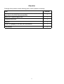
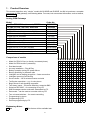
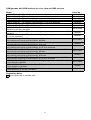
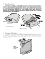
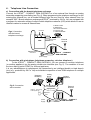
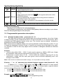
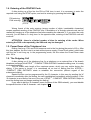
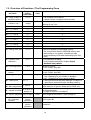
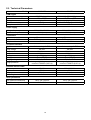
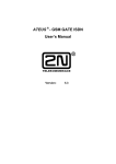
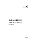
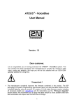
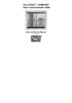
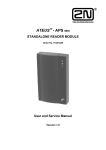
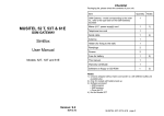
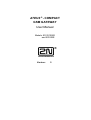
ATEUS ® - COMPACT
GSM GATEWAY
User Manual
Models: 910121052E
and 501052E
Version:
5
CONTENTS
1.
PRODUCT OVERVIEW
5
2.
BASIC DESCRIPTION
7
3.
PLACEMENT OF THE DEVICE
7
4.
TELEPHONE LINE CONNECTION
8
5.
CONNECTION OF AN EXTERNAL ANTENNA
9
6.
INSTALLATION OF THE SIM CARD
9
7.
RO AMING
9
8.
CONNECTION OF THE POWER SUPPLY
9
9.
INDICATION LED DIODE
10
10. SETTING OF THE DIL SWITCH
10
11. PROGRAMMING
11
12. PROGRAMMABLE P ARAMETERS DESCRIPTION
12.1. ALLOWED NUMBERS TABLE – PARAMETERS 00 - 10
12.2. SAVING A PIN – PARAMETER 20
12
FUNCTIONING (AT A TIME OF DIALING) - PARAMETER 21
12.3. A CHOICE OF SYMBOL
12.4. SPEECH VOLUME - PARAMETERS 22 AND 23
12.5. INCOGNITO - PARAMETER 24
12.6. DIALING TONE - PARAMETER 25
12.7. ECHO SUPPRESSION - PARAMETER 26
12.8. LENGTH OF NUMBER TO MAKE DIALING FASTER - PARAMETER 27
12.9. SERVICE PASSWORD - PARAMETER 78
12.10. INITIALIZATION – FUNCTIONS 98 AND 99
13. TONES ON THE TELEPHONE LINE
13
13
13
13
13
14
14
14
15
14. ENTERING OF THE PIN/PUK CODE
16
15. POWER DOWN OF THE TELEPHONE LINE
16
16. THE OUTGOING CALL
16
17. THE INCOMING CALL
17
18. TIPS TO S AVE TELEPHONE FEES DURING CONNECTION
TO A BRANCH TELEPHONE EXCHANGE
17
19. OVERVIEW OF FUNCTIONS / THE PROGRAMMING FORM
18
20. TECHNICAL P AR AMETERS
19
1
12
13
History
Version What is changed or new in this version
5
•
•
•
•
All applicable to dual-band model 501052E, with GSM engine TC35
Parameter 25 - Dialing tone selection (PSTN style / permanent)
Parameter 26 - Echo suppression (only for model 910121052E - with M20)
Parameter 27 - Length of number (for faster dialing)
2
Checklist
Package of this product contain following parts, check it please if necessary:
Item
Quantity
GSM Gateway - model corresponding to the order no., refer to the
type label on the GSM Gateway backside
1
Mains (A.C. power supply) cord
1
Telephone line cord
1
Antenna
1
Holder (for ganging to the wall) with accessories
1
This manual
1
3
Why do you need
The ATEUS ® – COMPACT GSM GATEWAY?
•
•
•
•
•
•
By connecting to your branch telephone exchange, it will be possible to automatically direct
outgoing calls to the mobile telephones network. You will thus save fees for connection
between the public network and the mobile telephones network. Incoming calls from a
mobile telephone of your customers or technicians out in the field will also be less
expensive.
You will have the possibility to connect an answering machine or a classical analog
telephone to the device working in the GSM network.
You will have telephone connection even at places where no public network lines are
established (mountain chalets, exhibitions, conferences,...).
The device is very well protected against overvoltage on the telephone line.
To operate the device, you do not need an external mobile telephone.
This is a modern device, its features include simple installation, small dimensions, and
reliability.
4
1.
Product Overview
This manual describes only “simple” models 910121052E and 501052E, but 2N ltd. produces a complete
assortment of GSM gateways, see following tables. For news, look some actual information, such as Internet,
www.2n.cz.
Analog GSM Gateways
Model
For PBX CO line, low cost, 900 MHz
For PBX CO line, low cost, dual band
Order No.
910121052
501052E
For PBX CO line, 900 MHz
For PBX CO line, back-up powered, 900 MHz
For PBX extension, back-up powered, 900 MHz
For PBX CO line, dual band
For PBX CO line, back-up powered, dual band
For PBX extension, dual band
For PBX CO line, for 19" rack, dual band
For PBX extension, for 19" rack, dual band
For PBX CO line, for 19" rack, 900 MHz
For PBX extension, for 19" rack, 900 MHz
Rack 19" with back-up power supply unit
910121053E
910121063E
910121061E
501100E
501063E
501061E
504063E
504061E
910121202E
910121203E
506000E
Comparison of models
•
•
•
•
•
•
•
•
•
•
•
•
•
•
•
•
•
•
•
Model for PBX CO line (or directly connected phone)
Model for PBX local line (extension)
Dual band model
An easy installation – Plug & Play
Battery operation during AC power failure
Barring possibility for selected calls
Intelligent end of dialling recognition – faster connection
Intelligent Incoming Call Routing
Service buffer – list of selected events and calls
Tariff pulse transmitter – e.g. for coin-phone
Begin & end of call signalling supported
Two binary inputs – for remote watching, transmits SMS
Serial port RS-232C – for connecting to any PC
SMS messages can be received & transmitted by PC
Data mode – can be used as a modem with any PC
Two universal switches – for remote controlling
Programming by phone
Programming by PC
Remote programming by PC
Explanatory Notes:
! Yes
! This feature will be available later
5
!
!
!
!
!
!
!
!
!
!
!
!
!
!
!
!
!
!
!
!
!
!
!
!
!
!
!
!
!
!
!
!
!
!
!
!
!
!
!
!
!
!
!
!
!
!
!
!
!
!
!
!
!
!
!
!
!
!
!
!
!
!
!
!
!
!
! ! ! !
! !
!
!
!
!
!
!
!
!
!
!
!
!
!
!
!
!
!
!
!
!
!
!
!
!
!
!
!
!
!
!
!
!
!
!
!
!
!
!
! !
!
! !
! !
! !
! !
!
! !
! !
! !
! !
! !
! !
! !
! !
! !
!
! ! ! !
!
! ! ! !
! !
! !
! !
! !
! !
! !
! !
! !
! !
! !
! ! ! !
! !
! !
GSM gatewas with ISDN interface for voice, data and SMS services
Order No.
Model
1 GSM / ISDN (NT + TE), 900 MHz
1 GSM / ISDN (NT + TE), dual band
2 GSM / ISDN (NT + TE) with two GSM gateways, 900 MHz
2 GSM / ISDN (NT + TE) with two GSM gateways, dual band
2 GSM / ISDN (NT + TE) with two GSM gateways, for 19" rack, dual band
1 GSM / 2 ISDN (2 NT + 2 TE) with physical LCR selection, 900 MHz
1 GSM / 2 ISDN (2 NT + 2 TE) with physical LCR selection, dual band
2 GSM / 2 ISDN (2 NT + 2 TE) with two GSM gateways and physical selection of LCR,
900 MHz, for 19" rack, dual band
2 GSM / 2 ISDN (2 NT + 2 TE) with two GSM gateways and physical selection of LCR,
dual band
2 GSM / 2 ISDN (2 NT + 2 TE) with two GSM gateways and physical selection of LCR,
for 19" rack, dual band
1 GSM / 2 ISDN (2 NT + 2 TE) with physical LCR selection
and automatic call routing to third networks, 900 MHz
1 GSM / 2 ISDN (2 NT + 2 TE) with physical LCR selection
and automatic call routing to third networks, dual band
1 GSM / 2 ISDN (2 NT + 2 TE) with physical LCR selection
and automatic call routing to third networks, for 19" rack, dual band
2 GSM / 2 ISDN (2 NT + 2 TE) with two GSM gateways, physical selection of LCR
and automatic call routing to third networks, 900 MHz
2 GSM / 2 ISDN (2 NT + 2 TE) with two GSM gateways, physical selection of LCR
and automatic call routing to third networks, dual band
2 GSM / 2 ISDN (2 NT + 2 TE) with two GSM gateways, physical selection of LCR
and automatic call routing to third networks, for 19" rack, dual band
2 ISDN (2 NT + 2 TE) special model without GSM gateway for automatic call routing
to third networks, 900 MHz
2 ISDN (2 NT + 2 TE) special model without GSM gateway for automatic call routing
to third networks, dual band
2 ISDN (2 NT + 2 TE) special model without GSM gateway for automatic call routing
to third networks, for 19" rack, dual band
Explanatory Notes:
These models will be available later
6
910121070E
502070E
910121072E
502072E
503072E
910121073
502073E
910121074E
502074E
503074E
910121081E
502081E
503081E
910121082E
502082E
503082E
910121080E
502080E
503080E
2.
Basic Description
The ATEUS ® - COMPACT GSM GATEWAY allows to access the GSM network in
connection with the branch telephone exchange equipped with the analog external line interface
(FXO) or in connection with an analog telephone appliance, a slot machine, answering machine,
etc. To operate the device, no additional devices are necessary (networking card, external GSM
telephone). Programmable parameters are preset to optimal values. After connecting a
telephone line, an antenna, power supply, and after installing the SIM card, it is possible
to realize telephone calls immediately.
Antenna FME
connector
Telephone Line,
RJ connector
Power supply
Euro connector
Fig. 1: Bottom view
Fig. 2.: Upper view
3.
Placement of the Device
The ATEUS ® - COMPACT GSM GATEWAY is designed for installation on vertical surface.
The workplace is shown in Fig. 3. The ATEUS ® - COMPACT GSM GATEWAY may not be
exposed to temperatures higher than 45°C which may occur at places with direct sun radiation
or near heat sources.
Fig.3.:
Operational
position
7
4.
Telephone Line Connection
a) Connection with the branch telephone exchange
Connect the ATEUS ® - COMPACT GSM GATEWAY to a free external line through an analog
transmitter supporting tone dialing (see Fig. 4). When programming the telephone exchange, for the
entering this external line, set a number different from the one used for other external lines, for
example "603". Branch telephone exchanges ATEUS ® produced by 2N Co. Ltd. are equipped with
a program for automatic routing of calls to mobile telephone networks (LCR) which allows to use an
identical number to access all external lines.
if called number
is 0603xxxxxx,
call number 603xxxxxx
to route this call
to GSM GATEWAY
CO lines
Fig.4: Connection
with the branch
telephone exchange
"603"
"0" "0"
line 12
13
14
15 Subscriber
PBX
External
antenna
lines
Telephone line
ATEUS - COMPACT
GSM GATEWAY
max 500 m
®
power supply
b) Connection with a telephone (telephone answering, coin-box telephone)
To the ATEUS ® - COMPACT GSM GATEWAY, you can connect a common telephone
(or another appliance) via the analog double-wire interface (see Fig. 5). The condition is to set
the tone dialing (option DTMF) for this end appliance.
It is very advantageous to complement this connection by an intelligent double or triple branch
joint (e.g., produced by 2N Co. Ltd) and distribute capacities of one GSM telephone to multiple
appliances.
Analog
phone
Telephone
answering
Fig.5.: Connection
with a terminal
Coinbox
telephone
External
antenna
TERMINAL
equipment
®
ATEUS - Ping pong
made by 2N Co.
Telephone
line
®
power
supply
8
ATEUS - COMPACT
GSM GATEWAY
5.
Connection of an External Antenna
Connect the external antenna cable, which you installed at the place with good GSM
network signal to the antenna FME connector. The antenna should be placed at least 2m away
from the GSM gateway. Antenna and cable parameters are given in chapter 20.
6.
Installation of the SIM Card
To register any GSM device to the mobile telephone network, a SIM card of some of the
GSM network operators is needed. The ATEUS ® -COMPACT GSM GATEWAY works with any
SIM card with logical levels of 3V from the GSM900 network operator.
Entering of the PIN may be enabled or disabled. Mode of the PIN code entering must be
programmed on the SIM card before its installation using the mobile telephone.
If the SIM card requires entering of the PIN, it is protected against being stolen. Anytime
after turning on, the PIN must be entered, or if the PIN is programmed to the EEPROM memory
the programmed PIN shall be entered automatically after turning on (see chapter 11).
If the protection by the PIN code is unblocked, after turning on of the ATEUS ® COMPACT GSM GATEWAY it is connected to the GSM network and ready to work within
several seconds.
Before installing the SIM card you must decide whether you shall use possibilities of
incoming redirection which are provided by GSM networks (redirection if the line is busy, if
none is present, if the device cannot be reached, ...). In connection with the branch telephone
exchange, it is usually advantageous to turn off all types of redirection and possibly use your
own answering machine.
Setting of Roaming parameters (calling through foreign GSM networks) - see chapter 7.
When installing the SIM card, remove the upper shield (see Fig. 2). Press the yellow
button of the SIM card reader using a suitable object so that the drawer moves out slightly. Take
out the drawer, insert the SIM card and push it back.
7.
Roaming
Using of roaming is set on the DIL switch according to chapter 0.
If you want to enable roaming and want to prefer some networks, fill the list of preferred
GSM networks using the mobile telephone.
Registration of the GSM gateway in a foreign GSM network is signaled by a dialing tone
(see chapter 12) and by the blinking type of the LED diode (see chapter 9).
If you disable roaming and the GSM gateway is registered in a foreign network, it is not
possible to realize any call, after dialing the first digit you obtain the line busy tone.
8.
Connection of the Power Supply
The only condition for connection of the power supply is to have previously installed the
antenna. If you connect the power supply to the device without an antenna, the
transmitter in the GSM module could be damaged. Manipulation of the telephone line, SIM
card, and DIL switches is possible during operation as well.
9
9.
Indication LED Diode
The LED diode indicates operational states always when the device is powered and is functional.
If the LED diode is not lighted nor does not blink, the device is not powered or is damaged.
Tab.1.: Operational states indicated by the LED diode:
Lighted permanently
Lighted 2s,
not lighted 200ms
Blinks with the
period of 2s
Blinks with the
period of 400ms
Device is functional and registered in the domestic GSM network
Device is functional and registered in a foreign GSM network ROAMING
Device is functional and is not registered to a GSM network because:
• SIM card is not installed
• PIN code has not been entered
• There is weak signal where the antenna is installed
Communication of the control processor with the GSM module is not
established (normally it is established 2s after turning on)
10. Setting of the DIL Switch
The DIL switch is used for simple programming of the basic parameters.
Switches no. 1 and 2 program the length of delay from the last called number until
starting to establish the connection (at the same time, it is the length of the maximum pause
which you can realize during the dialing). Switch no. 3 enables transmission of the access tone
during establishing of the connection. Switch no. 4 enables roaming. Setting of switches is
shown in Fig. 6.
For setting of the DIL Switch remove the upper shield (see Fig. 2).
SIM card reader
1 2 3 4
1.,2.:
time out 4 s
3.:
transmission of the acces
tone disabled
transmission of the acces
tone enabled
4.:
roaming disabled
time out 6 s
time out 8 s
time out 10 s
roaming enabled
Figr.6: Settings of the switches
10
11. Programming
Before you start to program
•
Use the prepared form (chapter 19), which also serves as a transparent table of all functions,
and input in it all values, which you intend to change.
•
If the GSM gateway is not completely new, ensure that you have the correct service password.
If you are not sure how the GSM gateway is programmed, use full initialization prior to
programming (Attention! the service password is initialized as well!).
Entering the programming regime
Programming of the GSM gateway is done via the telephone line with the DTMF option.
Programming cannot be done during a call and if the GSM gateway requires entering of the
PIN/PUK.
To enter the programming regime, dial the sequence
, after picking up the line, the
GSM gateway enters the mode of receiving of the service password (if you are dialing into the
busy line tone, its transmission is ended only after entering the whole sequence).
Enter the service password and finish the transmission by !. The GSM gateway sends the
confirmation/refusal signal. If the GSM gateway sends the refusal signal immediately after
entering of the introductory sequence, it is not possible to program the GSM gateway, the
EEPROM memory is damaged. In this case, initial values of all functions are set in the GSM
gateway.
If during entering the password you make a mistake, cancel its input by the character !
and start again from the introductory sequence.
The service password is set in the production to '12345'. We recommend to enter another
password so that your device is protected against unauthorized persons. If you forget the
password, your data are not lost yet - however, it is necessary to contact the producer.
Example - entering the programming regime:
The programming
As soon as you enter the programming mode, you can change any programmed value or
multiple values, in any order. The procedure is simple - first the function number is input, then its
value. The character
is used as the separator (as "Enter").
The function number has two digits (see chapter 19). After inserting this number and the
asterisk, the GSM gateway sends the confirmation/refusal signal according to whether your
input is correct. After entering the value and the second asterisk, the GSM gateway sends the
stored/confirmation signal, according to whether the value lies within the allowed range. The
programmed values are stored immediately.
Example - programming:
performs full initialization and stores the
current PIN.
Error during programming
If you make a mistake during entering of the number (both in the case of entering the
function number or the value) and find out about this mistake before pressing the asterisk, it is
possible to cancel the whole programming step by pressing the character .
If the GSM gateway sends the refusal signal, it is possible to continue programming - the
function number needs to be entered again even in the case that only the value was wrong.
If you program a value different from the one you wanted and the value is stored, you can
of course input the correct one again
11
Signaling during programming
Signal
Name Meaning
• Confirmation that the entered service password or the function number
Confirm.
was accepted and is correct
• When entering the service password, this signals that the password is
wrong
• After entering the sequence
, this signals malfunction of the
EEPROM memory
Refusal
• During programming, this signals that a wrong function number or
parameter number was entered
• Transmitted after cancellation of the password or function by the
character
Storing • Signals that the entered function value is correct and has been stored
Ending of programming
Hanging up of the telephone line ends programming.
After ending the programming, verify that the GSM gateway behaves according to your desires.
Store the filled programming form at a safe place.
12. Programmable parameters description
12.1. Allowed numbers table – parameters 00 - 10
This table can be used to limit outgoing calls only to allowed numbers. Up to first 6 digits
of dialed number can be compared with up to 10 rows of this table. If it is not found here, call is
cancelled and GSM gateway sends a busy tone. This function can be enabled / disabled by
parameter of function 00 (see table).
Use: If this function is disabled (default), the content of allowed numbers table has no effect. To use
it, enable the checking by function 00 (set to 1) and fill one or more rows of this table in any order.
It is important to find out how many digits must be entered to distinguish allowed and restricted
numbers.
Example:
• I need to allow 0601, 0602 … 0606: if I don't need to restrict e.g. 0600 or 0609, only 3 digits
are necessary: (060) and this requirement will occupy only 1 row of table.
• Furthermore, I need to allow 01, 02 … 09 but restrict all numbers, beginning 00: for this
requirement, 2 digits must be used (each group must be allowed separately) and it will
occupy 9 rows of table.
Note: If this function is enabled and a table is empty, it is not possible to call any number.
Entering „ * ” or „ # ” characters into allowed telephone numbers table (function 01 – 10)
In addition to 0 – 9 digits, DTMF dialing uses
and
characters for some special
functions. If it is necessary to enter
or
into allowed tel. numbers table, a special method
= „Enter” and
= „Cancel”:
must be used to differentiate it from
•
to enter
as a character, double-click
in a short interval (max. 0,5s).
•
to enter
as a character, double-click
in a short interval (max. 0,5s).
Example – to enter
"into function 01 dial:
(in the programming mode)
12
12.2. Saving a PIN – parameter 20
If Your SIM card is protected by PIN (i.e. PIN must be entered whenever after power on
to allow login into GSM network), this PIN can be saved into GSM gateway by function 20. In
this case, after each power on (e.g. after power failure) the PIN will be entered into SIM
automatically. Attention! Before saving PIN by function 20, log on to the GSM network must be
made previously!
Other eventualities:
• If Your SIM card is protected by PIN, but this PIN is not saved by function 20, after each
power on GSM gateway sends a "PIN tone" - a special tone used as a warning - and a PIN
is expected before dialing.
12.3. A choice of symbol
For symbol
functioning (at a time of dialing) - parameter 21
, the different interpretation can be selected by function 21 see chapter 16
12.4. Speech volume - parameters 22 and 23
Loudness can be adjusted by functions 22 and 23 separately for receive and transmit
direction with a step 3 dB (see table for limits).
12.5. Incognito - parameter 24
The function 24 allows disabling displaying of your telephone number on the display of the
called person. Initial value “preset“- automatic service setting according to provider setting.
Attention! Before you activate the incognito function “on”, check up if you have this service
enabled at GSM network provider. Otherwise, outgoing calls will not be realized at some
operators.
12.6. Dialing tone - parameter 25
The parameter 25 allows changing dialing tone form. Default is common dialing tone, well
known from PSTN (C.O.) lines. If you will change this parameter to “1“, permanent (continuous)
tone will be used. In this case, this tone will be used during roaming, too.
12.7. Echo suppression - parameter 26
Note: this parameter is applicable only to model 910121052E!!!
A parameter 26 allows a qualified person to change an echo-canceller parameter
"VoxGain". Default value is 8 for Greece GSM networks, and the range is 0 to 255. Echo
suppression is a built-in function of GSM gateway. It is able to reduce an echo effect, caused by
delay of GSM network. A greater value of this parameter can reduce the echo, but herewith it
can cause some distortion of speech, such as ineligible sounds during pauses in speech. This
parameter must be used with high caution, and only in exceptional events!
Important note: Only a second party can hear the echo, which is done by GSM
gateway. If a local user of GSM gateway hears an echo, it is done by mobile phone of second
party and it cannot be reduced by this parameter!
13
12.8. Length of number to make dialing faster - parameter 27
The function makes get through time shorter. It can be used under the condition that all
GSM networks to which you are going to call, have a fixed length of number (number of digits).
The parameter allows entering a maximal length of called number (number of digits). If the
lengths of the dialed number and the entered number are the same then GSM gateway sends
acknowledgement tone and starts getting through immediately. Thus, the process of getting
through is faster – otherwise the gateway waits for another e.g. 6 seconds to find out whether
the dialing was completed.
Notes:
•
•
•
•
•
•
•
If parameter 27 is set and subscriber dials a longer number (more digits than it is defined in
parameter 27) these surplus digits are ignored. Consequently, it is impossible to make e.g.
international calls, etc.
In this case, the subscriber will probably hear the operator message: “the dialing number is
incomplete”.
From the same reason it is not possible to use a number including the international prefix even if it is
a local GSM number, e.g. If you set the parameter 27 on value 10, you can dial number 0123456789
(10 digits) and you will get through. However, if you dial 0049 123456789 (13 digits!!) the GSM
gateway will send only 10 digits 0049 123456 !!!
If the dialed number is shorter (e.g. some GSM operators service numbers or emergency numbers
etc.) you will get through, it will only last a bit longer – the same as if you have not set parameter 27
or the parameter 27 is set to zero.
From this reason it is advisable to use the parameter even if GSM provider A uses 10 digits and
GSM provider B uses 9 digits. Set parameter 27 on 10, consequently the call to GSM network A will
be faster, the calling to GSM network B will not be sped up (no acceleration).
If you had set parameter 27 on 9 in the above mentioned case, you would have been able to make
calls to GSM network B faster however it would not have been possible to make calls to GSM
network A (10 digits), one digit is missing.
The parameter 27 and character # (tells GSM gateway last digit of called number was dialed, start
sending the number to GSM network – make the dialing faster) can be used together.
12.9. Service password - parameter 78
Service password can be changed by function 78. This password is used to protect a
programming mode entry. Default value is “12345”. Maximum length is 5 digits. Please don't
forget a new value, if you change it.
12.10. Initialization – functions 98 and 99
Function 99 can be used to turn all programmable parameters to default values, but it will
not erase an allowed numbers table.
For erasing an allowed numbers table, use function 98. This function has no effect a
parameter of function 00.
14
13. Tones on the Telephone Line
The ATEUS ® - COMPACT GSM GATEWAY sends to the end device which picked up the
telephone line, tones providing information on its operational state. Frequency of the tones, besides
the access one, is 425Hz.
Dialing tone 1:
•
Device is registered in the domestic GSM network
•
Device is ready to receive the dialing
•
This tone has identical parameters with the dialing tone on a common public network line
Dialing tone 2:
•
Device is registered in a foreign GSM network - ROAMING
•
Device is ready to receive the dialing
Note:
Both dialing tones described above will be used on the assumption that parameter 25 is set to
value “0” (default). If changed to “1“, permanent (continuous) tone will be used for both domestic
GSM network and roaming.
Ringing tone:
•
The called participant is free and is being rung at
•
This one is transmitted by the GSM network
Busy line tone:
•
The called participant's line is busy
•
Connection is lost
•
The called number has too many digits (more than 20)
•
Device is registered in a foreign network but roaming has been disabled by the DIL switch
•
SIM card is not installed
•
GSM gateway is not registered in GSM network
•
Failure of communication of the control processor with the GSM module, servicing
Intervention required
•
This tone has identical parameters with the busy tone on a common public network line
Access tone:
•
Receiving of the dialing is finished, connection is being established
•
Lasts 3 s, its frequency is 800 Hz
•
Sending of the tone can be disabled by setting of the DIL switch
PIN tone:
•
Entering of the PIN code is required
•
This tone is sent after turning on if entering of the PIN code is not blocked on the SIM card
PUK tone:
•
Entering of the PUK code is required
•
It is sent after repeated wrong entering of the PIN code and blocking of the SIM card
PIN/PUK OK:
•
Tone 2 s long, notifies of correct entering of the PIN or PUK code
15
14. Entering of the PIN/PUK Code
If after picking up of the line the PIN or PUK tone is sent, it is necessary to enter the
required code using the DTMF option, and end its entering by pressing the button .
PIN entering:
PUK entering:
your PUK
new PIN
Wrong format of the code entering (wrong number of digits, inadmissible characters)
causes repeated sending of the PIN/PUK tone. Cancellation of a wrongly entered code can be
realized by hanging up of the telephone line before sending the character !. If you enter the code
correctly, you will hear a 2 s long tone. In the opposite case, entering of the PIN/PUK code will
continue.
ATTENTION - there is a limited number of tries for entering of the codes. When
entering the PUK code repeatedly, the SIM card may be damaged!
15. Power Down of the Telephone Line
Dialing, line busy, PIN, and PUK tones are sent to the line during the period of 60 s. After
this time elapses, the line is set in a state without power supply (Power Down state), which lasts
until the line is not hung up. In the programming mode, the line enters the Power Down state
after 180 s.
16. The Outgoing Call
If after picking up of the telephone line (by a telephone or an external line of the branch
telephone exchange) the ATEUS ® - COMPACT GSM GATEWAY sends the dialing tone, it is ready
to receive the dialing.
The DIL switch sets length of the maximum pause, which you may realize during the
dialing. If the pause is longer, it is considered as an end of dialing and the ATEUS ® COMPACT GSM GATEWAY starts to establish the connection (without regard of the
subsequent dialing).
Special function can be programmed for the '#' character, in this case by sending the '#'
character immediately after the dialing, the call is established immediately without waiting. (If the
'#' character is send as the first one in the row, ATEUS ® - COMPACT GSM GATEWAY stops to
send the dialing tone and keeps awaiting the dialing.)
If you want to dial the '#' character (some functions of the GSM network), you must disable
the special function of the '#' character - see chapter 11.
16
17. The Incoming Call
Incoming calls are signaled by ringing of the telephone line common on the public network
fixed telephone lines (ringing for 1 s, pause 4 s). The branch telephone exchange detects the
incoming call and behaves according to the way it is programmed. If only the telephone is
connected to the telephone line, it starts ringing.
After picking up of the telephone line, the incoming call is interconnected. Until this
moment, the calling participant obtains the ringing tone, and the participant is not charged with
any fees.
If the ATEUS ® - COMPACT GSM GATEWAY is connected to the branch telephone
exchange, by suitable programming of the telephone exchange it is possible to transfer such
ringing to one or more internal participants.
If enabled by the telephone exchange, it is possible to use calling via the DISA selection
when the telephone exchange picks up the line automatically and provides the calling person
with a message on what place he/she has reached, and that he/she can dial the number of the
internal participant directly via tone dialing. In this configuration, it is advantageous to program
the telephone exchange in such a way so that if the called participant is not present or if the line
is busy, the incoming call is directed to an operator, voice box or answering machine because
this attempt to connect is charged to the calling person.
18. Tips to Save Telephone Fees during Connection to a Branch Telephone
Exchange
•
•
•
•
Selection of suitable tariff when purchasing the SIM card. Large operational load in the
outgoing direction is assumed, and thus tariffs with more expensive lump sum are
advantageous, which usually provide lower fees for the call unit.
If your employees are equipped with mobile telephones, they will be able to call the firm from
anywhere without the need to use the public network fixed line.
If it is enabled by your telephone exchange, program the automatic start of calling to the
mobile telephone network via the ATEUS ® -COMPACT GSM GATEWAY. In this way you
ensure that everyone will use this possibility, and you will save the maximum of resources.
In the case of modern branch telephone exchanges, it is possible to program authorization
of the dialing for every user individually. To maximize saving of telephone fees when calling
to the GSM network, divide the user into three groups:
1. No possibility to call the GSM network (when they try to call, they receive the line
busy tone from the telephone exchange),
2. Possibility to call the GSM network via the ATEUS ® - COMPACT GSM GATEWAY
only (if the ATEUS ® - COMPACT GSM GATEWAY is busy, they receive the line
busy tone),
3. Possibility to call the GSM network via public network lines as well in the case that the
ATEUS ® - COMPACT GSM GATEWAY is occupied by another call.
All possibilities of programming the branch telephone exchanges described in this
manual are provided by telephone exchanges of the series ATEUS ® produced by 2N Co.
Ltd.
17
19. Overview of Functions / The Programming Form
Function number
and name
00 – using of table of
allowed numbers
01 – table of allowed
numbers, row 1
Range of
values /
Initial value
0,1 / 0
New
value
Explanation
0 - all numbers can be dialed
1 - dialed number is compared with the table
First 6 or less digits of the allowed telephone number
max. 6 digits
/ empty
Deleting of row: #$!!
02 – – // –, row 2
– // –
– // –
03 – – // –, row 3
– // –
– // –
04 – – // –, row 4
– // –
– // –
05 – – // –, row 5
– // –
– // –
06 – – // –, row 6
– // –
– // –
07 – – // –, row 7
– // –
– // –
08 – – // –, row 8
– // –
– // –
09 – – // –, row 9
– // –
– // –
10 – – // –, row 10
– // –
– // –
20 – saving of the PIN
0,1 / 0
0- PIN is not entered from EEPROM memory
1- The current PIN is stored in EEPROM memory, and
after turning on, it is entered. (Possible only after
previous entering of PIN when transmitting of the PIN
tone)
21 – function of the
character !
0,1 / 1
22 – receiving volume
1-5 / 3
Receiving volume,
1= min. 5=max., step 3dB
23 – transmitting
volume
1-5 / 3
Transmitting volume,
1= min. 5=max., step 3dB
0 - “Preset“- setting according to the network provider
1 -“On“- Displaying of your number is disabled
2-“Off“ – Displaying of your number enabled
0 - dialing tones according with drawings in chapter 12
1 – permanent (continuous) tone including roaming
A greater value can reduce the echo, but it can cause
some distortion of speech. Model 910121052E only!
Dialing ends when the number of digits is equal the value
set in this parameter.
0 = length of number is not watched
24 –Incognito
25- –Dialing tone
model 910121052E only!
1- ! has properties described in chapter Chyba!
Nenalezen zdroj odkazů.
0,1,2 / 0
0,1 / 0
26 - Echo suppression
0...255 / 8
27 - Length of number
0, 3 up to 16
default 10
78 - Service password up to 5 digits
98 – initialization of
tab. of allowed
numbers
99 - full initialization
0- ! is understood as dialing
enter the
service
password
enter the
service
password
12345
Don't forget a new value, if you change it !
Deletes rows of the table, has no effect on setting of
the function 00
Sets all values to the initial ones including the service
password!
18
20. Technical Parameters
Model:
910121052
501052
GSM900 phase 2
FR and EFR
plug-in, 3V
2W
-104 dBm
GSM900 & GSM 1800 phase 2+
HR, FR and EFR
plug-in, 3V
2W / 900 MHz, 1W / 1800 MHz
-105 dBm
230 V±10%, 50/60 Hz
10 VA (max.)
230 V±10%, 50/60 Hz
10 VA (max.)
Euro connector
FME connector, male
RJ 6/2
Euro connector
FME connector, male
RJ 6/2
2-wire analog a/b FXO
48 VDC
30 mA max.
1200 Ω max.
425 Hz
Tone (DTMF)
45 V RMS / 50 Hz
4 stages, lightning arrester to
current of 10000 A (8/20 µs)
2-wire analog a/b FXO
48 VDC
30 mA max.
1200 Ω max.
425 Hz
Tone (DTMF)
45 V RMS / 50 Hz
4 stages, lightning arrester to
current of 10000 A (8/20 µs)
900 MHz
50 Ω
2W min.
0 or 3-10 m
900 / 1800 MHz
50 Ω
2W min.
0 or 3-10 m
150 x 150 x 55 mm
0°C–45°C
150 x 150 x 55 mm
0°C–45°C
GSM engine
Mobile tel. network type
Speech codec
SIM card
Max. Transmission power
Reception sensitivity
Power supply
Voltage, frequency
Power consumption
Connectors
AC mains (supply)
External antenna
Telephone line
Telephone interface
Type
Loop voltage
Loop current
Loop resistance
Dialing tone
Dialing
Ringing voltage
Surge protection
Antenna with the cable
Frequency
Impedance
Output power
Cable length
Other parameters
Size (without connectors)
Operational temperature
19
The product is to be used for purposes for which it has been designed, in accordance with this manual.
Producer reserves the right for such modification of the product against the presented
documentation which shall lead to improvement of the product features.
The ATEUS ® - COMPACT GSM GATEWAY includes no components harmful for the
environment. If this product can no more serve for the original purposes one day and can no more be
used by you or elsewhere, dispose of it in accordance with valid legal provisions.
20
21
© 2001, 2N Co. Ltd. - Prague
22
PS 775, v5