1
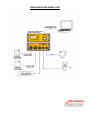
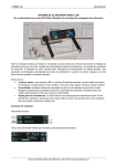
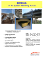
DYMAS
24 bit Dynamic Monitoring System
DYNAMIC MONITORING OF CIVIL AND
INDUSTRIAL STRUCTURES
• Rugged, small, low power
• From 3 to 96 channels
• 24 bit multichannel sampling
• 10 Hz – 10 Khz sample rate
• Bandwidth DC - 8 kHz
• Continuous and/or triggered recording
• Built-in calibration function
• 2 Gb internal memory for 6 channels group
• Geophones and/or accelerometers connection
DYMAS
high
resolution
dynamic
acquisition system can operate as
vibrational or microseismic unit in
standalone or multi-station configuration.
They fully respect international standards
DIN4150-3, DIN45669-1 e UNI9916
requirements.
DYMAS typical employing is dynamic
monitoring of civil and industrial structures
as bridges, viaducts, chimneys, plants for
rock noise and movements caused by
natural seismic events or generated during
excavation or blasting.
DYMAS is integrated with VIBROSOFT
configuration, communication, processing
and visualization software.
DYMAS
24 bit Dynamic Monitoring System
Technical features
System
Input channels Configuration Timing Triggering mode Recording mode Data storage Diagnostics Power consumption Communication 24 bit module Converter Channels Input level Calibration Sampling Bandwidth Dynamic range Programmable gain (per channel) Filter Anti Aliasing External interfaces Ethernet GPS antenna Power Seismic sensors Other sensors (optional) Other interfaces Physical characteristics Temperature Dimensions (LxWxH) Weight From 1 to 6 sensor channels digital recorder each unit, till to 96 channels Standalone or multi‐station network
Internal RTC updated via GPS or remote control – simultaneous sampling Threshold level and/or STA/LTA, selectable for each channel
Internal/external trigger, continuous, time or remote, selectable post‐ trigger length
Recording of weighted pick values (min‐Max), according to DIN 4150 part II, selectable from 1 to 100 s 2 Gb internal memory card for 6 channel group (till to 32GB optional) Battery voltage, temperature, sensors test 1 W for 6 channel group (active)
Ethernet TCP/IP via cable/wireless, modem, GPS, USB2.0
Individual 24‐bit Sigma/Delta per each channel, with DSP each 6 channels, integrated digital antialiasing filter 6 channels each unit 5Vpp, 20Vpp, differential Input Built‐in Selectable from 10 Hz to 10,000 Hz
DC – 8,000 Hz > 122 dB 1‐2‐4‐8‐16‐32‐64‐128
Digital Filter FIR . Frequency attenuation by Nyquist (1/2 sample rate) >–120dB, cut frequency 0,4 of sample rate RJ‐45 configuration via pc or remote connection GPS time synchronization, RS‐422 interface
3VDC to 30 VDC (adapter 120/240 V AC optional), automatic turn OFF when battery <10,2 V, turn ON >11,8V Seismometers, Accelerometers Force Balance, ICP, piezoeletrics, MEMS, Geophones, Extensometer, termocouples, hydrophones, piezometers
USB/ RS‐232/RS‐422/ modem
‐20 °C ‐ +50 °C 25 cm x 21 cm x 7,5 cm ( 6 channels )
3,50 kg ( 6 channels )
CONFIGURATION SINGLE UNIT CONFIGURATION IN NETWORK Ultrasonic System Central Data Acquisition Unit
Ultrasonic system
CMS
MANUAL
Versione e Data
Identificativo
Data stampa
Versione 07 del 07/12/2007
Ultrasonic System CMS - User manual
26/04/2010
Totale pagine
41
ultrasonic CMS v.3.1/7-English
INDEX
1.
GENERAL CHARACTERISTICS .................................................................................................... 4
1.1.
1.2.
1.3.
1.4.
2.
TECHNICAL SPEC’S CMS SYSTEM ................................................................................................... 5
CHARACTERISTICS OF THE PIEZOELECTRIC RECEIVER ................................................................. 6
CHARACTERISTICS OF THE PIEZOELECTRIC TRANSMITTER .......................................................... 7
CHARACTERISTICS OF THE HAMMER-TRANSDUCER ................................................................... 8
PREAMBLE ......................................................................................................................................... 9
2.1. IDENTIFICATION OF THE CENTRAL ACQUISITION UNIT AND ITS ACCESSORIES........................... 9
2.2. PRECAUTIONS .................................................................................................................................... 9
2.3. CONNECTIONS .................................................................................................................................. 10
2.4. BATTERY AND FUSES ....................................................................................................................... 10
2.5. “ON/OFF”-PUSHBUTTON AND SIGNALS ........................................................................................ 11
2.5.1. ON/OFF –pushbutton ..................................................................................................................... 11
2.5.2. Signals ............................................................................................................................................ 11
Led “Power Status” ..................................................................................................................................... 11
Led “Stand by” ............................................................................................................................................ 11
Led “Arm” ................................................................................................................................................... 11
3.
START OPERATION ....................................................................................................................... 12
3.1. OPERATION OF THE PDA WITH THE PRE-LOADED POCKETSONIC SOFTWARE........................... 12
3.1.1. Switching “ON” and “OFF” the PDA ............................................................................................ 12
3.1.2. Starting Page of the Interface Software ......................................................................................... 12
3.1.3. Selecting “PocketSonic” …… ....................................................................................................... 12
4.
4.1.
4.1.1.
4.1.2.
DATA ACQUISITION - FUNCTION ................................................................................. 14
DATA ACQUISITION FUNCTION – INITIAL SCREEN: .......................................................... 15
Setting of the Acquisition Parameters: ........................................................................................... 15
Data Acquisition Function - Data and Acquisition Profile Management ................................. 18
4.2.
DATA ACQUISITION FUNCTION - VISUALIZATION - SCREEN ............................................ 20
4.2.1. Software Buttons ............................................................................................................................ 21
Transmitter Sensor’s Remote Push-button: ................................................................................................. 21
4.3. EDIT AND SAVING OF THE DATA.................................................................................................. 25
…..loading data from ARCHIVE… ............................................................................................... 25
4.3.1. EDIT- Command............................................................................................................................ 26
4.3.2. REPEAT - Command..................................................................................................................... 27
Tipology
Prog:SG02; Doc:MAN.12.03
Title
Ultrasonic System CMS - User manual
Version & File
Versione 07 del 07/12/2007
Pag.
of
2
41
ultrasonic CMS v.3.1/7-English
4.3.3.
4.3.4.
4.3.5.
4.3.6.
4.3.7.
Ed - Command ............................................................................................................................... 28
INFO - Command .......................................................................................................................... 29
SAVE - Command ......................................................................................................................... 29
CLEAR - Command....................................................................................................................... 31
DISPLAY - Command ................................................................................................................... 31
5.
ARCHIVE-DETAIL FUNCTION ....................................................................................... 32
6.
“EXIT” FUNCTION ............................................................................................................. 32
7.
CONFIGURATIONS & INFO FUNCTION ................................................................................... 33
……..SELECTING CONFIGURATIONS (CALIBRATION &/OR CHANGING CONFIGURATION) ............. 33
….SELECTING INFO…................................................................................................................................ 34
8.
INSTALLATION OF THE PROGRAM ACTIVESYNC ON THE PDA OR ON THE PC ...... 35
9.
“POCKET SONIC” SOFTWARE - INSTALLATION ................................................................. 35
10.
WAREHOUSING OF THE CENTRAL UNIT AND OF THE PDA. ......................................... 35
11.
“DATASONIC SYSTEM” PROGRAM ........................................................................................ 36
11.1.
11.2.
11.3.
PREAMBLE...................................................................................................................................... 36
INSTALLATION OF THE SOFTWARE ONTO A PC........................................................................... 36
DATA TRANSFER ............................................................................................................................ 36
Tipology
Prog:SG02; Doc:MAN.12.03
Title
Ultrasonic System CMS - User manual
Version & File
Versione 07 del 07/12/2007
Pag.
of
3
41
ultrasonic CMS v.3.1/7-English
1.
General characteristics
The SolGeo ultrasonic CMS System Unit measures with high precision the propagation time (First
Break Pick) through various materials of high velocity, compression waves (P waves). Waves with low
velocity response can also be measured by using the Hammer-Transducer encompassed with the System
Unit. The set-up of the measurement can be direct, semi-direct or indirect.
The main components of the SolGeo ultrasonic CMS Measurement System are:
¾ 1xCentral Data Acquisition Unit with HP-IPAQ PDA and the pre-installed SolGeo-PocketSonic
Software
¾ 2xEmitters - Piezoelectric transducer > 1,6 kV, 55kHz, 20kHz
¾ 1xHammer – Piezoelectric transducer for low frequency (sonic) signals
¾ 1xReceiver – piezoelectric transducer: 55 kHz (optional il 20-80 kHz)
¾ 1xCD-ROM with SolGeo-DATASONIC Software for usage on Desk- or Lap-Top PC’s
The proprietary software SolGeo-PocketSonic is pre-installed on the PDA, integrated within the Central
Data Acquisition Unit and allows to display, to compute and to directly store all acquired data. In addition,
the dynamic elastic Young-module: Ed can be readily computed and stored, by introducing the
corresponding material density values as well as the relevant Poisson Coefficient.
The PDA device can be easily carried-on during the measurement process. Thank to the Bluetooth
connection, the unit can be used up to a distance of 30m from the Central Data Acquisition Unit. The
acquired data can be synchronized and transferred to any PC by using either the built-in RS232 or the
USB or the Bluetooth interface.
The pulse’s transmission power of the highly sensitive active piezoelectric receivers with 55 kHz (optional
20-80kHz) resonance frequency allows undertaking measurements on sample materials in a lab
environment or directly on construction sites.
The Central Data Acquisition Unit contains, besides the electronic circuitry to generate high tension pulses
for the transmitter and the treatment of the signal coming from the receiver, an A/D digitalization board.
The system, operating at a sampling frequency of 1.25 MHz allows digitalizing the full wave profile of the
acquired signal and displaying it as with an oscilloscope on a time-amplitude diagram.
The transmitter sensor is equipped with a push-button allowing to remote control the Data Acquisition
Central Unit for starting the measurement, for storing the measured data and for resetting the unit for a
new measurement. This procedure allows remote operation of the Central Unit whilst conducting
measurements at a distance of about 30m from the Central Unit itself. Furthermore this set-up allows
operating the system by only one person.
In addition to the pre-installed proprietary SolGeo-PocketSonic Software for PDA’s, the system is
delivered with a CD-Rom with proprietary software for usage with PC’s. The SolGeo-DATASONIC
software, allows to down-load, to compute and to display the acquired data on PC’s. Additionally by
inserting data’s acquired with a SCHMIDT-Hammer device together with the relevant coefficients it is
possible to compute the concrete’s samples resistance coefficients by mean of the SONREB methodology.
The data can furthermore be exported in ASCII format to be made accessible to commercial posttreatment programs like, e.g. MATLAB.
Tipology
Prog:SG02; Doc:MAN.12.03
Title
Ultrasonic System CMS - User manual
Version & File
Versione 07 del 07/12/2007
Pag.
of
4
41
ultrasonic CMS v.3.1/7-English
1.1.
Technical Spec’s CMS System
- Converter type
A/D, 12 bit converter
- Display range
+/- 2.5 Volt
- Amplification
Software driven; selectable gains: x 10, x 100, x 1000, x 5000.
- Acquisition
frequency
From 50Khz to 1.25Mhz
- Acquisition Buffer
-Standard 2048 samples (optional up to 8192 samples)
-Duration of Acquisition from 1.6 ms to 40ms.
- I/O between Central
Unit & internal PDA
Standard multi-purpose connector with direct insertion into the PDA:
- I/O Central Unit – PDA: Bluetooth, reach about 30 m.
- Internal PDA battery reloading .
- I/O between Central
Unit & external PC
Surface mounted connector Type DB15:
- I/O Central Unit - PC (use without PDA): RS232 serial type, baud rate
selectable from 1200 to 115.000 bps.
- USB I/O to transfer data from the internal PDA to an external PC.
- Power Supply
VDE connector 110 a 240Vac 50-60Hz:
- Internal battery recharging unit: 500mA.
- Internal PDA Power Supply: 5Vdc, 2A.
- Internal battery: 12V, 3.2Ah.
- Stand-by: 50 hours, in operation: 10 hours.
- Total recharging time: 8 hours.
- Transducers
- Receivers: Piezoelectric type, 55 kHz resonance frequency, optional 20-80 kHz,
internally pre-amplified Receiver - 20 dB.
-Transmitter: Piezoelectric type: Voltage for transmission pulse: 1,6 kV with
push-button trigger for remote control functions, data acquisition functions,
signal freeze and storage of data for data profile management.
-Ready for use with piezoelectric Hammer Transducer for low frequency
signal measurements.
- Case
Tipology
Prog:SG02; Doc:MAN.12.03
- Waterproof, standard IP67
- Shock resistant and non-corroding.
- Equipped with pressure gauge.
- Pre-installed PDA attachment and external PC connectivity
- Dimensions 270W x 240D x 170H
- Weight 5 Kg without sensors
Title
Ultrasonic System CMS - User manual
Version & File
Versione 07 del 07/12/2007
Pag.
of
5
41
ultrasonic CMS v.3.1/7-English
1.2.
Characteristics of the piezoelectric Receiver
- Frequency Range
1kHz – 70kHz
- Amplification
Preamplifier 20 dB – Gains software driven: x10,x100,x1000,x5000.
- Weight
760 gr.
- Dimension
Ø:50 mm x l:75 mm
Receiver RSG-55
Tipology
Prog:SG02; Doc:MAN.12.03
Title
Ultrasonic System CMS - User manual
Version & File
Versione 07 del 07/12/2007
Pag.
of
6
41
ultrasonic CMS v.3.1/7-English
1.3.
Characteristics of the piezoelectric Transmitter
- Frequenza impulso
TSG55 = 55KHz
TSG-Hi20 = 20 KHz
- Transmission Pulse,
Voltage
1,6kV
1.6kV
- Energy
approx. 0,05 Joule
approx.0,2 Joule
- Weight
770 gr.
1450 gr
- Dimension
Ø:50mm x l:75 mm
Ø:66 mm x l:100 mm
Transmitter TSG-55
Tipology
Prog:SG02; Doc:MAN.12.03
Title
Ultrasonic System CMS - User manual
Transmitter TSG-Hi20
Version & File
Versione 07 del 07/12/2007
Pag.
of
7
41
ultrasonic CMS v.3.1/7-English
1.4.
Characteristics of the HAMMER-Transducer
The HAMMER-Transducer equipping the CMS System is meant for use when the energy of the
piezoelectric transmitters TSG-55 & TSG-Hi20 is not sufficient to trespass the material under inspection.
In such circumstances the arriving signal is too weak to be correctly analyzed and the First Break Pick
time can hardly be determined.
The signal produced with the help of the HAMMER-Transducer is characterized by low frequency and
high energy.
This device is therefore ideal for usage on materials with low propagation characteristics (like
“monumental” masonry) and/or materials of very large size.
Tipology
Prog:SG02; Doc:MAN.12.03
Title
Ultrasonic System CMS - User manual
Version & File
Versione 07 del 07/12/2007
Pag.
of
8
41
ultrasonic CMS v.3.1/7-English
2.
Preamble
2.1.
Identification of the Central Acquisition Unit and its Accessories
The Central Acquisition Unit, the transducers and the PDA are labelled by an ID-label and a SerialNumber. For connection cables and other accessories the serial number is not contemplated.
Model
Description
CMS V3HLF
IPAQ 2190
PocketSonic
Central Acquisition Unit, version 3
PDA, HP IPAQ series hx2100 256Mb
PDA Software
DataSonic System PC Software
TSG-55
Piezoelectric transmitter 55 KHz
RSG-55
Preamplifier piezoelectric receiver 55KHZ
TSG-Hi20
Piezoelectric transmitter 20 KHz
03HXX
Hammer
Connection cable RG-58 through hammer and
central acquisition unit.
PDA/Bluetooth/Universal Connector-Cable
Connection cable PC ÅÆ central acquisition
unit.
2.2.
Serial-Number, location
& version
SG02.00xx, front side
Under the battery
In the menu “Info”
In the menu “Info”
TSG55sn.03T0xx, front side
RSG55sn.03R0xx, front side
TSG-Hi20sn.04T0xx, front side
sn. 03H0xx, hammer handle
Comments
HP product
Opzional
Precautions
Some precautions to be observed when using the acquisition system.
•
Connect and Disconnect the PDA/Bluetooth/Universal Connector-Cable only when
Central Unit is switched off.
• During operation of the transmitting transceiver a 1,6 kV pulse is generated. Always be
certain that the connection cable and the connectors are not damaged before
operations.
• Connect or disconnect the Unit from the Power Supply only when System is switched
to OFF.
• By rapid changes in Temperature, before powering-ON the Acquisition System make sure that
no condensation in the connectors has developed.
Tipology
Prog:SG02; Doc:MAN.12.03
Title
Ultrasonic System CMS - User manual
Version & File
Versione 07 del 07/12/2007
Pag.
of
9
41
ultrasonic CMS v.3.1/7-English
2.3.
Connections
Before operating the CMS Central Unit make sure that the transducers cable are connected to the
corresponding connector:
•
•
The Transducer (Transmitter), model TSG-XX has to be connected to the
“TRANSMITTER/HAMMER” connector.
The transducer (receiver), model RSG-XX has to be connected to the “RECEIVER” connector.
By using the PDA in “remote” mode (disconnected from the Central Unit) do not disconnect from the
Central Unit the PDA/Bluetooth/Universal Connector-Cable otherwise the Bluetooth connectivity will be
disabled.
2.4.
Battery and Fuses
Position the PDA with the help of the Velcro strip and connect it with the PDA/Bluetooth/Universal
Connector-Cable to insure battery recharging.
The PDA unit will still be recharged either if the CMS Central Unit is connected or not to the power
supply net.
The CMS Central Unit is generally operated by using its internal battery.
When attached to the Net and the power switch ( 0 1 ) is “1”, the internal battery of the Unit
are under re-charge. Leaving the unit attached for longer than 24 hours to the power supply net does not
harm the internal battery.
To preserve duration of the battery make sure that the battery is charged completely at least once every
three months during 8 hours.
When the Unit is switched to “1”, the red light of the switch has to be lit. Should this not be the case make
sure that the device fuse (fast, 500mA) is integer, otherwise exchange it by using the spare fuse contained
in the fuse section of the VDE connector of the Central Unit.
Tipology
Prog:SG02; Doc:MAN.12.03
Title
Ultrasonic System CMS - User manual
Version & File
Versione 07 del 07/12/2007
Pag.
of
10
41
ultrasonic CMS v.3.1/7-English
2.5.
“ON/OFF”-pushbutton and Signals
2.5.1.
ON/OFF –pushbutton
Switch the Central Unit “ON” by pressing the ON-button: “Power Status” and “Stand by” leds will
illuminate.
Switch the Central Unit “OFF” by pressing the OFF-button. All led have to switch-off as well.
2.5.2.
Signals
Three main led-lights:
Led “Power Status”
This led indicates the power supply status of the Central Unit:
•
•
lit up:
flashing:
•
off:
The Central Unit is ON and working and the internal battery if fully loaded.
The Central Unit is ON and working the internal battery is “LOW”.
As soon as the internal battery voltage reaches a “LOW-est threshold level”, the
internal firmware to the Central Unit will automatically shut-down the System.
The Central Unit is shutting down or is already “OFF”.
Led “Stand by”
In order to protect the battery, the High-Voltage generator is switched-off after 15 seconds of inactivity.
The “stand by” led is also switched-off, signalling that the unit is not operational. (“INACTIVE”)
When the sensor: HAMMER-Transceiver has been selected on the PDA’s PocketSonic software, the
“stand by led” will permanently be lit (“ACTIVE”).
Led “Arm”
This led is flashing during the short duration of the data acquisition. (measurements operation)
When the sensor: HAMMER-Transceiver has been selected on the PDA PocketSonic software, the “Arm
led” will permanently be lit (“ACTIVE”), waiting for the impact trigger from the HAMMER-Transceiver.
The led flashes when the HAMMER-Transceiver impacts,
Tipology
Prog:SG02; Doc:MAN.12.03
Title
Ultrasonic System CMS - User manual
Version & File
Versione 07 del 07/12/2007
Pag.
of
11
41
ultrasonic CMS v.3.1/7-English
3.
Start Operation
Before starting the Central Unit make sure that the PDA/Bluetooth/Universal Connector-Cable is inserted,
to make sure that the Bluetooth transponder is ready for operation.
Start the Central Unit by pressing the ON button. The led “Power Status” & “Stand by” will lighten to
signal operation readiness.
3.1.
3.1.1.
Operation of the PDA with the pre-loaded PocketSonic software
Switching “ON” and “OFF” the PDA
Switch the PDA “ON”. If the PDA is attached to the PDA/Bluetooth/Universal Connector-Cable it will
switch-on automatically. Select “Start” from the starting Menu to initiate the execution of the
“PocketSonic” Program.
Make sure that software program is correctly terminated before switching “OFF” the PDA, otherwise a
RESET of the PDA will be necessary.
The operating status of the PDA is automatically saved when the system is switched-off and restarted
when the system is switched-on.
3.1.2.
Starting Page of the Interface Software
3.1.3.
Selecting “PocketSonic” ……
Tipology
Prog:SG02; Doc:MAN.12.03
Title
Ultrasonic System CMS - User manual
Version & File
Versione 07 del 07/12/2007
Pag.
of
12
41
ultrasonic CMS v.3.1/7-English
….. the start-page of the program will be opened:
The main functions represented on the screen are:
•
Acquisition
Starts the Data Acquisition function
•
Archive
Management of the Storing of data and measurements profiles
(See also paragraph 5 page 32)
•
Exit
Ends the execution of the program
Lower Menu-Bar:
•
Configurations
Selection of extended calibration parameters
•
Info
Program version
Tipology
Prog:SG02; Doc:MAN.12.03
Title
Ultrasonic System CMS - User manual
Version & File
Versione 07 del 07/12/2007
Pag.
of
13
41
ultrasonic CMS v.3.1/7-English
4.
Data Acquisition - Function
Starting the signal’s acquisition function.
The Bluetooth connection is automatically activated. (The PDA/Bluetooth/Universal Connector-Cable
has to be always inserted in its socket whilst operating the PDA in Bluetooth connection mode).
A) Verification of the correct “activation” of the Bluetooth connection:
1) The “blue-led” on the PDA/Bluetooth/Universal Connector-Cable inserted connector has to be lit.
2) No “CONNECTION ERROR”- message on the screen
B) The Bluetooth connection is not correctly “activated”:
1) Message: “CONNECTION ERROR” will appear
2) Acknowledge the error message and “EXIT” the program
3) Select “RESET” (The PDA will reset)
4) On the Central Unit: press “OFF” and subsequently press “ON”.
5) Verify that on the starting screen the “ANTENNA”-Icon is not crossed with a red “X”
6) Should the “ANTENNA”-Icon be crossed, than select it to activate the function.
7) The Bluetooth set-up screen will appear
8) Select the Bluetooth Symbol button.
9) Wait until the button turns “GREEN”
10) Leave by pressing OK
11) Go to: 3. Start Operation (see page 12) and follow the start-up procedure anew.
Tipology
Prog:SG02; Doc:MAN.12.03
Title
Ultrasonic System CMS - User manual
Version & File
Versione 07 del 07/12/2007
Pag.
of
14
41
ultrasonic CMS v.3.1/7-English
4.1.
4.1.1.
•
Data Acquisition Function – initial screen:
Setting of the Acquisition Parameters:
Pre-defined configuration mode (Standard operational mode)
This selection allows switching from manual to pre-defined measurements values (of various
specimen).
By selecting a pre-defined value, the values for frequency, amplification and acquisition time are
automatically set.
Selection of
Pre-defined Mode
Length of the
test specimen
Short Specimen
Medium Specimen
Long Specimen
5 - 30 cm
30 – 100cm
> 100cm
Sampling
Frequency
(kHz)
1250
1000
250
Acq. time
(µsec)
Gain
(x)
800
1000
4000
10
100
1000
Table 1: Pre-defined measurementsValues
• Power
Allows, selecting the power setting of the Transmitting Transducer.
This function is helpful for avoiding saturation at the Receiving Transducer during the measurement
of small specimen.
Transmitting Power is varied by moving the cursor button from minimum (left) to maximum (right).
The power setting is only active when the option “Amplification” is set to “LOW POWER”.
Tipology
Prog:SG02; Doc:MAN.12.03
Title
Ultrasonic System CMS - User manual
Version & File
Versione 07 del 07/12/2007
Pag.
of
15
41
ultrasonic CMS v.3.1/7-English
• Amplification
Allows the setting of the amplification level to which the analogical signal is submitted to before
being converted into digital. This method allows the optimal exploitation of the internal 12-bit sampler
within the +/- 2.5V range, even by very weak signals.
5 different amplification levels can be selected: Low Power, 20, 40, 60 or 70 dB.
The amplification level will vary according to the different materials to be investigated.
The selection of the amplification value can also be changed during the acquisition of the signal by
mean of a selection button on the acquisition screen-mask.
The scale for amplitude values is absolute and corresponds to the voltage values of the output signal
from the Receiver.
• Sampling Frequency
It allows the manual selection of the most opportune sampling frequency in relation to the desired
acquisition time.
The manual selecting of the sampling frequency entails the automatic selection of the maximum
number of samples available (standard: 2048).
• Acquisition time µs
Selects the duration of signal acquisition.
To illustrate the arrival time of a signal, together with the maximum frequency allowing for an
acceptable graphic representation.
The table hereunder displays acquisition time in relation to the acquisition frequency selected.
Acquisition
(sampling)
Frequency
(kHz)
Resolution
(µsec)
(sampling time)
Maximum
Acquisition time
(µsec)
Fs
Ts = 1/Fs
Tacqmax.=Ts x 2048
1250
1000
500
250
200
100
50
0,8
1
2
4
5
10
20
1600
2000
4000
8000
10000
20000
40000
Table 2: Acquisition time ÅÆ frequencies (standard 2048).
Tipology
Prog:SG02; Doc:MAN.12.03
Title
Ultrasonic System CMS - User manual
Version & File
Versione 07 del 07/12/2007
Pag.
of
16
41
ultrasonic CMS v.3.1/7-English
First Break Pick of compression waves P
(msec)
Max . Signal Freq.
(kHz)
250 x Ts
Fmax = Fs/5
(where 250 approx.10% of 2048)
0.2
0,25
0,5
1
1,25
2,5
5
250
200
100
50
40
20
10
Table 1b: Recommended
First Break Pick
= 0,25 msec
0
200 400 600 800 1000 1200 1400 1600 1800 2000
Tacqmax
First Break Pick = 0,25 msec
Ts = 1 µsec ; Fs = 1000 kHz ; Fmax = 200 kHz
Tacqmax
= 2000 µsec
Tipology
Prog:SG02; Doc:MAN.12.03
Title
Ultrasonic System CMS - User manual
Version & File
Versione 07 del 07/12/2007
Pag.
of
17
41
ultrasonic CMS v.3.1/7-English
•
Transmitter
Selects the type of Transmitter to be used:
o Sensor (TSG-xxx)
Standard piezoelectric transducer emitting continuously energy pulses.
o Hammer
By selecting “Hammer” the Central Unit is in permanent stand-by for the hammer-blow trigger
signal from the “Hammer”.
The led “ARM” lightens. After every hammer-blow trigger, the Central Unit rearms
automatically.
At the End of the setting of the Acquisition Parameters press OK.
4.1.2.
Data Acquisition Function - Data and Acquisition Profile
Management
All data related to acquired data profiles, their measurements and related characteristics are stored
temporarily in a file: Temp.prf. under: \MyDocuments\
For every measurement, all data related to the digitalized signal are stored in a file: Temp_xxx.prs where
xxx is given by the index ID of the measurement.
When the Data and Acquisition Profile Management page is accessed, all information (contained in a file:
Temp.prf ) related to the done profile measurements are displayed:
The display:
Tipology
Prog:SG02; Doc:MAN.12.03
Title
Ultrasonic System CMS - User manual
Version & File
Versione 07 del 07/12/2007
Pag.
of
18
41
ultrasonic CMS v.3.1/7-English
ID:
Is an automatic incremented number for the identification of every measurement. This index is the “xxx”
characterising the file containing the digitalized signal.
Step:
This parameter allows introducing, either the intermediate distance between measurements of a profile or
the identification number of a test on a specimen.
All measurements related to the same measurement point shall be related to the same step. For every new
measurement, the value of “step” is automatically set to zero. To set a value: see paragraph “EDIT”
(see 4.3.1 page 26).
Leg:
Represents the distance between Transmitter and Receiver. The “leg” of the signal traversing material.
This value can be modified: see paragraph “EDIT” (see 4.3.1 page 26).
Time:
Represents the First Break Pick time value of the measure displayed. This value cannot be edited it can
only be varied by repeating the measurement.
Velocity:
It is the value computed as the ratio between the distance “Leg” and the “Time” of a measurement. This
value is automatically computed.
All measurements within a profile-file can be edited and repeated. A single measurement cannot be
eliminated from the profile-file. Changing a single measurement (ID-xxx) is possible only through
the new acquisition of the same (ID-xxx) measurement.
To secure a correct interpretation of the measurement’s data by the DataSonic software when down-loaded
from the PDA onto the PC, it is recommended to observe the following guidelines:
•
To eliminate an intermediate measurement: Set the values for “Leg” (distance) and “Step” to
zero.
•
Whilst acquiring profiles; insert the same value for Step for the first measurement point and the
subsequent ones.
•
In case of several measurements for a single point, insert the same value for Step and Leg for the
measurements.
Tipology
Prog:SG02; Doc:MAN.12.03
Title
Ultrasonic System CMS - User manual
Version & File
Versione 07 del 07/12/2007
Pag.
of
19
41
ultrasonic CMS v.3.1/7-English
4.2.
Data Acquisition Function - Visualization - Screen
The screen shows the acquired signal together with additional
signal values. The selection buttons related to foremost
useful visualization functions are also displayed.
Velocity:
The value represents the ratio between measured time and length of the specimen or width of the
object under review. The time value is automatically reduced by the selected “delay” value
(see: chapter 7 page 33).
First Break Pick Time:
Generally the value is determined in “automatic”. In case of blurred signal, it is recommended to
select “manual” (see: soft-button: Threshold Setting). The value displayed is reduced by the selected
“delay” value (see: chapter 7 page 33).
Graphic Representation of the Signal:
The acquired signal is plotted with “Time” on the x-Axes and “Amplitude” on the y-Axes.
The value-scaling for the graphic’s grid for Amplitude and Time are depicted on the upper part of the
graphic, together with amplification gains of the receiver system in decibel.
The activation of the function “Low Power” is also shown with the symbol “low”.
If activated, the black vertical - and the green horizontal lines represent respectively the starting point
from which the “First Break Pick Time” is recorded and the “Capture Threshold” used in the
“automatic mode”.
On the right side of the screen a cursor allowing varying in 6 steps the power of the transmitter when
the “Low Power” Function is on.
Tipology
Prog:SG02; Doc:MAN.12.03
Title
Ultrasonic System CMS - User manual
Version & File
Versione 07 del 07/12/2007
Pag.
of
20
41
ultrasonic CMS v.3.1/7-English
4.2.1.
Software Buttons
The following functions are assigned to the following buttons:
•
•
: Shows the “screen” related to the processing mode (see: 4.1.2 page 18).
ON
:
This button is used to enable or disable the signal acquisition. The related led is lit when acquisition is
“ON”.
•
Leg
Distance between the Receiver- and the Transmitter-Transducer, namely the width/thickness of the
investigated object. Can be varied by selecting the “Leg” button.
By selecting this button the value of the distance (width/thickness of the object under review) between
Receiver and Transmitter can be defined.
• Memo :
Stores the measurement of the actual signal (under a temporary file) and “reboots” the system for the
next measurement.
To this button is associated a “led-type” light that briefly flashes when the function “store” is
activated over the push-button on the transmitter.
Transmitter Sensor’s Remote Push-button:
The push-button on the transmitter allows the operator the handling from a remote position of
the freeze - and of the store - function.
In the “acquisition mode” the signal acquisition is performed in continuous.
If the push-button on the transmitter is pressed once, the signal acquisition on the PDA switches
from continuous to the “one shot mode”.
Every additional press-touch of the push-button activates a new signal acquisition and its
visualization.
If the push-button is pressed and hold for at least 3 sec, than when released, the data storing
function is performed, similar to the Memo” function as described above.
The “led-light” on the screen, associated to the “Memo” function, lightens-up briefly.
The continuous acquisition mode is automatically activated again.
The switch back and forth from the manual- to continuous- operational mode can only be done
by performing the storing function as described above.
•
Scaling Amplitude:
Like in an Oscilloscope the function allows varying the mV/grid scaling for the visualization of the
Amplitude. The selected scaling value is related to the input-signal only and is independent from the
amplification (GAIN) selected.
Tipology
Prog:SG02; Doc:MAN.12.03
Title
Ultrasonic System CMS - User manual
Version & File
Versione 07 del 07/12/2007
Pag.
of
21
41
ultrasonic CMS v.3.1/7-English
Scaling Time:
•
The watch symbol activates the selection in µsec or msec/division of the time scale represented.
Should a selected scaling be wider than the selected acquisition time, than the software automatically
rescales the scaling factor. When the selection is set to “automatic” the presentation scale is
automatically resetted in order to visualize the whole signal.
•
Threshold setting:
Drop-down menu allowing selecting between automatic- or manual-mode the reading mode of the
First Break Pick Time of the compression waves P.
o
Show Cursor: Enables or disables the cursors related to the trigger point and to the time
measured.
o
Manual Measurement: Allows selecting directly on the graphic the “First Break Pick
reading point”. By using a zoom function the reading can be rendered more precisely.
o
Automatic Measurement: The automatic computation of the First Break pick reading
point is activated. The calculated offset is deducted from the visualized signal. (see: Capture
Errore. L'origine riferimento non è stata trovata. “Errore. L'origine riferimento non è
stata trovata.” page Errore. Il segnalibro non è definito.)
•
Zoom:
The zoom function allows a more precise display of the signal at the First Break Pick point. Therefore
offers a better verification possibility of the correctness of the measured data. The zoom function is
“switched-off” when the button is selected again.
Gain:
•
Allows to select the gain of the amplification of the receiver transducer’s signal and to select the
“Low Power” function.
Tipology
Prog:SG02; Doc:MAN.12.03
Title
Ultrasonic System CMS - User manual
Version & File
Versione 07 del 07/12/2007
Pag.
of
22
41
ultrasonic CMS v.3.1/7-English
Measurements example
Tipology
Prog:SG02; Doc:MAN.12.03
Title
Ultrasonic System CMS - User manual
Version & File
Versione 07 del 07/12/2007
Pag.
of
23
41
ultrasonic CMS v.3.1/7-English
TX
RX
TX
Tipology
Prog:SG02; Doc:MAN.12.03
Title
Ultrasonic System CMS - User manual
Version & File
Versione 07 del 07/12/2007
Pag.
of
24
41
ultrasonic CMS v.3.1/7-English
4.3.
EDIT and SAVING of the data
To EDIT a profile already stored:
•
Select the icon
……
(i.e. loading the data from the Archive)
!
…..loading data from ARCHIVE…
The window shown allows selecting the file-directory and displays a file-list with extension
compatible to the program.
Tipology
Prog:SG02; Doc:MAN.12.03
Title
Ultrasonic System CMS - User manual
Version & File
Versione 07 del 07/12/2007
Pag.
of
25
41
ultrasonic CMS v.3.1/7-English
By “pointing” with the PDA-pen the name of a file, all related data will be loaded into a temporary
acquisition file.
•
•
•
4.3.1.
The profile is loaded into temporary files
Adjourn the data
SAVE Data under the same or a new name
EDIT- Command
To edit data of a measurement:
•
•
•
Select with the PDA-pen the index ID of the measurement.
The index ID will be highlighted with a blue background colour.
Select the EDIT button
After this step, a numerical keyboard will be displayed to insert the distance between sensors. (LEG)
(cm):
Select the OK button to confirm the new entry
Tipology
Prog:SG02; Doc:MAN.12.03
Title
Ultrasonic System CMS - User manual
Version & File
Versione 07 del 07/12/2007
Pag.
of
26
41
ultrasonic CMS v.3.1/7-English
....automatically a new numerical keyboard will be displayed
…. The STEP of the measurements has to be defined…..
Step (cm):
Select the OK button to confirm the new entry.
At the end of this procedure all new values will be displayed on the data management screen.
4.3.2.
REPEAT - Command
To repeat a measurement:
•
Point with the PDA-pen the index ID of the measurement
•
The index ID will be highlighted in blue
•
Select the button REPEAT
•
The previous values for Time and Velocity will be set to zero.
•
Select the OK button, the display of the profiles will be closed and
•
The Visualization Screen (see 4.2 page 20) will be opened
Within the acquisition menu, next to the MEMO button the index
of the measurement to be repeated is displayed.
After having repeated and stored the measurement, the index will position itself
automatically on the following position after the last measurement recorded into the table.
Note:
When selecting the “ON”-button, the error box can be displayed with the message: “Processing Mode!!”,
than :
• Quit the error box
• Close the screen by pressing OK on the upper right corner
• Restart the Menu: “ACQUISITION” (see chapter 4 page 14)
Tipology
Prog:SG02; Doc:MAN.12.03
Title
Ultrasonic System CMS - User manual
Version & File
Versione 07 del 07/12/2007
Pag.
of
27
41
ultrasonic CMS v.3.1/7-English
4.3.3.
Ed - Command
By selecting this function the menu for the computation of the
dynamic Young-Module Ed is accessible.
The computation can be done by taking into account either
the average velocity of the whole measurements profile or a
single velocity value.
To make the computation it is mandatory to insert the
related material density parameters (g/cm3) and
the Poisson Coefficient.
The value of Ed is expressed in MPa.
The computed values as well as the selected parameters are stored in
the file header of the profile file (FILENAME.prf) and are displayed
again for control purposes when the command “SAVE” is selected.
It is only possible to change them by entering the computation
menu “Ed” again.
Tipology
Prog:SG02; Doc:MAN.12.03
Title
Ultrasonic System CMS - User manual
Version & File
Versione 07 del 07/12/2007
Pag.
of
28
41
ultrasonic CMS v.3.1/7-English
4.3.4.
INFO - Command
This function allows reviewing after the saving of the data, the file header of the profile file
(FILENAME.prf) with the parameters used to compute the dynamic Young Module Ed.
In the Note-Box alphanumerical text to qualify the measurement can be introduced.
To leave select OK or Cancel
4.3.5.
SAVE - Command
This command allows saving and naming the acquired data,
stored in temporary files.
Tipology
Prog:SG02; Doc:MAN.12.03
Title
Ultrasonic System CMS - User manual
Version & File
Versione 07 del 07/12/2007
Pag.
of
29
41
ultrasonic CMS v.3.1/7-English
…………To continue press OK……
The next display-box allows to select:
•
•
•
•
The name
Under which the measurement profile shall be saved.
The PocketSonic program will automatically add a
progressive number to the measurement ID.
This will allow identifying all files in which the
digitalized signal for every measured point is stored.
The folder
Under which all data of the profile are contained.
The type, or file extension
It cannot be modified.
The Location
The saving path or type of storage device used. As internal resources storage device can be
selected: Main memory or external storage expansions, like Memory Stick SD or Compact Flash
if available...
Selecting SAVE the data will be saved and the temp.prf file is copied to the file “FILENAME.prf”
All files related to the stored signal are converted to the new name: “FILENAMEn_IDn.prs”.
Tipology
Prog:SG02; Doc:MAN.12.03
Title
Ultrasonic System CMS - User manual
Version & File
Versione 07 del 07/12/2007
Pag.
of
30
41
ultrasonic CMS v.3.1/7-English
4.3.6.
CLEAR - Command
By selecting the CLEAR button all temporary files are cleared!!.
4.3.7.
DISPLAY - Command
This function allows reviewing and changing the values of the signal previously stored.
The profile data display will be substituted by the display of the signal selected in the Processing Mode
with the same procedure as described under paragraph: 4.3.1 page 26
It is therefore possible to:
•
Change the scale for TIME and AMPLITUDE
•
Activate the ZOOM function
• Change the DISTANCE (leg) value
The signal acquisition function is disabled. By selecting the ON-button the message-box “Processing
Mode!!!” will be displayed, indicating that the mode in use is not compatible with the “New Signal
Acquisition Mode”.
To return to the “Processing Mode” Screen select:
.
Once in the “Processing Mode” Screen, it allows the selection of another measurements point or to restore
the normal data acquisition mode (OK function) without modifying the data stored.
.
Tipology
Prog:SG02; Doc:MAN.12.03
Title
Ultrasonic System CMS - User manual
Version & File
Versione 07 del 07/12/2007
Pag.
of
31
41
ultrasonic CMS v.3.1/7-English
5.
Archive-Detail Function
Allows accessing the data of the profiles, editing them and storing them in a file. Further information are
to be found under 4.1.2
6.
“EXIT” Function
Select this option to end executing the program. Do not use the button “ X” in the top right corner to
end executing the program; in this case the program would be still executing in the background with the
consequence that all resources used would not be freed-up. This might cause operational problems.
In the event that this “faulty” operational mode should incur, the best viable solution is to (HARDWARE)
“RESET” of the PDA.
The importance of the above described switch-off sequence is because of the fact that a Bluetooth
connection is in use which can only be terminated by shutting-down the serial I/O’s before terminating the
program execution itself.
Switch-off the CMS Central Unit only after having executed the above described sequence.
Tipology
Prog:SG02; Doc:MAN.12.03
Title
Ultrasonic System CMS - User manual
Version & File
Versione 07 del 07/12/2007
Pag.
of
32
41
ultrasonic CMS v.3.1/7-English
7.
Configurations & Info function
Note:
Configurations are set based on tests with calibrated specimen at SolGeo’s Quality Control
Department. (QCD)
Should the need occur for changing the set values, than select “configurations” on the lower menubar: (see 3.1.3 page 12).
……..selecting Configurations (CALIBRATION &/or Changing Configuration)
This function allows setting the calibration and computation parameters:
(piezoelectric) System Delay (µsec)
The First Break Pick reading, either automatic or manual, is adjusted by the value inserted in this field.
The value to be inserted (calibration of the Unit) is depending on the transducer used and is determined by
differencing the time recorded in a measurement with the time measured in a certified probe of the same
material.
Hammer Delay (µsec)
The Hammer Delay value is normally -20. This value is preset at SolGeo’s QCD.
Tipology
Prog:SG02; Doc:MAN.12.03
Title
Ultrasonic System CMS - User manual
Version & File
Versione 07 del 07/12/2007
Pag.
of
33
41
ultrasonic CMS v.3.1/7-English
Capture Threshold (mV)
When used in “Automatic Capture Mode”,intercepts the measured signal in a point as close as possible to
the x-Axes. From this intercept point the PocketSonic Software computes via an algorithm the First Break
Pick reading of the captured signal wave. This parameter can be manually modified whilst acquiring data
to further improve the determination of the First Break Pick.
Offset Points
This parameter is relevant when the determination of the First Break Pick is in “Automatic Capture
Mode”. It is used to compute an eventual constant offset value to be deducted from the initial segment of
the acquired signal to further improve the determination of the point of First Break Pick. Generally the
values used are between 10 and 50.
Capture Threshold Cursor
The cursor “Capture Threshold” is displayed on the graphics. (green line parallel to x-Axes)
Time Cursor
The cursor “Time” is displayed on the graphics. (black line parallel to y-Axes)
….selecting Info…
Selecting the button it displays the loaded Software Release in use.
Tipology
Prog:SG02; Doc:MAN.12.03
Title
Ultrasonic System CMS - User manual
Version & File
Versione 07 del 07/12/2007
Pag.
of
34
41
ultrasonic CMS v.3.1/7-English
8.
Installation of the program ActiveSync on the PDA or on the PC
Before connecting the PDA to the PC it is mandatory to install the ActiveSync Software on the PC.
9.
“POCKET SONIC” Software - Installation
After a (hard-) RESET of the PDA the backup file to reinstall the Pocket Sonic Software can be found on
the CD delivered with the equipment.
10.
Warehousing of the Central Unit and of the PDA.
If the Central Unit is warehoused during a longer period of time, make sure that once a month the unit is
powered-on in order to recharge the internal battery.
Same applies to the PDA unit. Important: Make sure that the PDA/Bluetooth/Universal Connector-Cable
is disconnected from the PDA when the PDA is not in use.
Tipology
Prog:SG02; Doc:MAN.12.03
Title
Ultrasonic System CMS - User manual
Version & File
Versione 07 del 07/12/2007
Pag.
of
35
41
ultrasonic CMS v.3.1/7-English
11.
11.1.
“Datasonic System” Program
Preamble
The software package “ Datasonic System” allows the management of data that
have been transferred from the PDA to a PC .
The following data presentations are possible:
¾ Graphics
¾ Oscillogramms
¾ Personalized Reports for Customers
Furthermore, the software allows to:
¾ Review every single acquired signal
¾ Review the time of “First Break Pick”, the acquired data amplitudes and modifying the files.
¾ To compute the concrete’s resistance with the SONREB Methods by mean of sclerometric
measurements.
¾ To compute the dynamic Young Module Ed by inserting material density and the Poisson
coefficient.
¾ Export signals in bitmap format
¾ Export data in ASCII format
11.2.
Installation of the Software onto a PC
Insert the by-packaged CD-Rom into the PC.
Id the CD does not boot automatically, than use the SETUP program and follow the instructions.
Before connecting the PDA for the first time to the PC, install the ACTIVE SYNC Software (see 3.3.3.3.)
Define with the ACTIVE SYNC a data transfer path between PC and PDA, also for the PDA “File Folder”
in addition to the other options, like: contacts, activities, etc.
After this, launch the DATA SONIC System.
11.3.
Data Transfer
Click on the icon “Datasonic” in the “Datasonic” folder of the menu START Æ PROGRAMS.
The following picture is displayed from which different options can be selected:
¾ Input Data from CMS (Down-loading the data)
¾ Compute Data (Processing and Computation of data already acquired)
The option: Data Acquisition from CMS is disabled.
This option can only be activated with a separate licence. Pls. contact your dealer or SolGeo.
Tipology
Prog:SG02; Doc:MAN.12.03
Title
Ultrasonic System CMS - User manual
Version & File
Versione 07 del 07/12/2007
Pag.
of
36
41
ultrasonic CMS v.3.1/7-English
After selecting Compute Data (Processing and Computation of data already acquired)
The program will prompt the user with the following “screen”, where:
¾ Construction site – meant is the main geographical reference, town, place, etc. of the
measurements’ file
¾ Lot – meant is the location within the Construction site ,where various measurements profiles
have been acquired.
¾ Profile – meant a unambiguous profile of measurements over n-points
Tipology
Prog:SG02; Doc:MAN.12.03
Title
Ultrasonic System CMS - User manual
Version & File
Versione 07 del 07/12/2007
Pag.
of
37
41
ultrasonic CMS v.3.1/7-English
After having started the program following operations have to be performed:
¾ Input data for the new Construction site
¾ Input data for a Lot within the construction site
On the PC click on the “Import”-button and select the directory “PDA-name-My documents” and all subdirectories containing all acquired profiles “*.prf” .
All data related to the selected profile will appear in the nearby multiline text-box.
It is also possible to down-load all data files (“*.prf “ & “*.prs”) onto the PC.
By clicking on the “Export” – button all profile stored can be exported to “text.format: *.txt”
Select one profile at the time and press the “Memo” button.
Æ
A window will be opened and the file can be renamed the measurement distance
between adjacent points can be defined as well as the orientation vertical or horizontal of the
profile.
After this the file can be saved. (OK)
Tipology
Prog:SG02; Doc:MAN.12.03
Title
Ultrasonic System CMS - User manual
Version & File
Versione 07 del 07/12/2007
Pag.
of
38
41
ultrasonic CMS v.3.1/7-English
Once all relevant profiles have been selected click on the button: “Detail” and all profiles will be shown
in a single graph:
Similarly, if the button: “Grouping” is selected; selected profiles can be added or dragged with the mouse
(by clicking twice on the profile and by keeping the right button pressed) to the graph.
Tipology
Prog:SG02; Doc:MAN.12.03
Title
Ultrasonic System CMS - User manual
Version & File
Versione 07 del 07/12/2007
Pag.
of
39
41
ultrasonic CMS v.3.1/7-English
Within the Profile Management screen, following options are available:
“Signal” :
all acquired signals can be reviewed, the scaling can be changed at wish and the point of the First Break
Time can be zoomed by opening a zooming-window with the left mouse-button.
By dragging in the right direction the selected area will be enlarged; by dragging in the left direction the
enlarged area will be scaled back to original size.
Within the “Signal” option, other options available are:
¾ “Refresh” : the cursor will position itself again on the original First break Point determined at the
moment of data acquisition. (The SONIC POCKET PDA-Software allows the First Break point
to be manually or automatically determined.)
¾ “Modify” : the cursor value can be modified and overwritten. A vertical dimension line (blue) is
displayed with the help of which the value of the original First break Point will be accurately
determined.
¾ “Cursor” : on the right-side of the box containing the y-axes value, an horizontal dimension line
(yellow) is displayed with the help of which the amplitude of the original receiver signal will be
accurately determined. The amplitude value is represented in “absolute terms”, i.e. that the value
is not related to the amplification coefficient selected at the time of data acquisition. Allowing
thus the comparison in absolute terms of the acquired signals, their amplitudes and their loss.
¾ EXPORT: the data related to the displayed wave-shape are converted into an ASCII data-file
allowing the import into commercial software applications.
Tipology
Prog:SG02; Doc:MAN.12.03
Title
Ultrasonic System CMS - User manual
Version & File
Versione 07 del 07/12/2007
Pag.
of
40
41
ultrasonic CMS v.3.1/7-English
¾ “Save BMP” : the data will be available in a Bitmap format.
“Computation” :
The dynamic YOUNG-Module Ed and the resilience of concrete with the SONREB Method can be
computed.
By selecting the button “New” a data profile can be manually introduced
By selecting the button “Print” a print-out report of the data profile can be obtained.
Header and Footer Comments can be defined and personalized by:
¾ selecting among: “text”, “graphic” for the Header
¾ and “Footer-Graphic” for the Footer.
This report format can only be globally selected from the drop-down menu bar in the opening page of the
“COMPUTE DATA” Mode.
By selecting the button “ Delete” singular profiles or entire measurements group can be deleted.
By selecting “EXIT”, the program resets itself at the initial screen.
Tipology
Prog:SG02; Doc:MAN.12.03
Title
Ultrasonic System CMS - User manual
Version & File
Versione 07 del 07/12/2007
Pag.
of
41
41