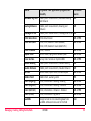
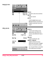
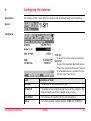
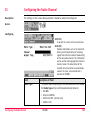
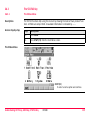
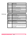
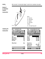
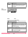
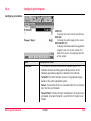
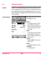
1
Leica GPS900
Technical Reference Manual
Version 2.0
English
Introduction
Purchase
Congratulations on the purchase of a GPS900 Series instrument.
)
To use the product in a permitted manner, please refer to the detailed safety directions in
the User Manual.
Product identification
The type and the serial number of your product are indicated on the type plate.
Enter the type and serial number in your manual and always refer to this information when
you need to contact your agency or Leica Geosystems authorized service workshop.
Type:
_________________________
Serial No.:
Symbols
The symbols used in this manual have the following meanings:
Type
)
)
Trademarks
Introduction
_________________________
•
Description
Important paragraphs which must be adhered to in practice as they enable
the product to be used in a technically correct and efficient manner.
The RX900 controller is available as RX900 with internal memory or as RX900c with
external CompactFlash card (CF card). The name RX900 and the term internal memory is
used througout the manual and may also represent the RX900c and the term CF card.
• Windows and Windows CE are a registered trademark of Microsoft Corporation
• Bluetooth is a registered trademark of Bluetooth SIG, Inc
All other trademarks are the property of their respective owners.
GPS900
2
Table of Contents
In this manual
Chapter
Page
PART 1 - The System
1
2
3
Table of Contents
Managing, Creating, Editing Jobs
11
1.1
1.2
1.3
11
13
14
Accessing Job Management
Creating a New Job
Editing an Existing Job
Managing, Creating, Editing Points/Data
16
2.1
2.2
2.3
2.4
2.5
2.6
Accessing Data Management
Creating a New Point
Editing an Existing Point
Viewing the Data Log
Point Sorting
Terminology
16
18
21
25
27
29
Managing, Creating, Editing Codes/Codelists
38
3.1
3.2
3.3
3.4
3.5
3.6
3.7
38
40
41
42
44
46
48
Overview of Codelists
Accessing Codelist Management
Creating/Editing a Codelist
Accessing Code Management
Creating/Editing a Code
Managing Job Codes
Terminology
GPS900
3
4
Managing, Creating, Editing Coord Systems
54
4.1
4.2
4.3
4.4
54
57
59
61
61
63
65
65
67
68
68
71
72
72
73
75
76
77
4.5
4.6
4.7
4.8
4.9
5
Table of Contents
Overview of Coordinate Systems
Accessing Coordinate System Management
Creating/Editing a Coordinate System
Transformations
4.4.1
Accessing Transformation Management
4.4.2
Creating/Editing a Transformation
Ellipsoids
4.5.1
Accessing Ellipsoid Management
4.5.2
Creating/Editing a Ellipsoid
Projections
4.6.1
Accessing Projection Management
4.6.2
Creating/Editing a Projection
Geoid Models
4.7.1
Overview of Geoid Models
4.7.2
Accessing Geoid Model Management
4.7.3
Creating a Geoid Model from the Internal Memory
CSCS Models
Terminology
Converting Data - Copy, Export, Import
80
5.1
5.2
5.3
80
82
87
Copying Points Between Jobs
Exporting Data from a Job
Importing Data to a Job
6
Configuring the Antenna
93
7
Configuring the Codes and their Attributes
95
8
Configuring the Coordinate Quality Control
97
GPS900
4
Table of Contents
9
Configuring the Display Mask
10
Configuring the HOT Keys and the USER Menu
102
11
Configuring the Instrument Identification
104
12
Configuring the Language
105
13
Configuring the Local Time Zone
106
14
Configuring the Point Occupation Settings
107
15
Configuring the Radio Channel
109
16
Configuring the Satellite Settings
111
17
Configuring the Screen Display
113
18
Configuring the Units and Formats
116
19
Using the Tools - Activating Licence Keys
123
20
Using the Tools - Calculating with Calculator
126
20.1
20.2
20.3
20.4
20.5
126
127
129
131
135
Overview of Calculator
Using the Calculator in RPN Mode
Using the Calculator in Standard Mode
Description of Softkeys
Configuring the Calculator
99
21
Using the Tools - Formating Objects
137
22
Using the Tools - Transferring Objects
138
GPS900
5
23
Using the Tools - Uploading Software
141
24
Using the Tools - Viewing Data
144
25
Understanding MapView
147
25.1
25.2
25.3
25.4
25.5
25.6
147
149
153
154
155
156
26
Table of Contents
Overview of MapView
Configuring MapView
MapView Components
MapView Components
MapView Components
MapView Components
-
The
The
The
The
Softkeys
Screen Area
Toolbar
Point Symbols
Understanding HOT Keys, USER key, STATUS Key
157
26.1
26.2
26.3
157
158
159
159
160
163
167
169
171
172
The HOT Keys
The USER Key
The STATUS Key
26.3.1 The Status Menu
26.3.2 Status Satellite Information
26.3.3 Status Real-Time Data Input
26.3.4 Status Current Antenna Position
26.3.5 Status Battery Level and Memory Usage
26.3.6 Status System Information
26.3.7 Status Radio Information
GPS900
6
PART 2 - The Applications
27
28
29
30
Table of Contents
Working with COGO
174
27.1
27.2
27.3
27.4
27.5
27.6
27.7
174
175
178
180
185
188
192
An Overview of the Program
Starting the Program
Calculating with Inverse
Calculating with Intersections
Calculating with Lines
Calculating with Arcs
Configuring the Program
Working with Determine Coord System
193
28.1
28.2
28.3
28.4
28.5
28.6
193
198
200
208
209
216
An Overview of the Program
Starting the Program
Determining a New Coord System using the Normal Method
Updating an Existing Coord System using the Normal Method
Determining a New Coord System using the One Pt. Local. Method
Configuring the Program
Working with GPS Resection
217
29.1
29.2
29.3
217
218
219
An Overview of the Program
Starting the Program
Using the Program
Working with Reference Line
223
30.1
30.2
30.3
30.4
30.5
223
225
228
233
239
An Overview of the Program
Starting the Program
Measuring to a Reference Line/Arc
Staking to a Reference Line/Arc
Configuring the Program
GPS900
7
31
32
33
Working with Setup Reference
242
31.1
31.2
31.3
242
243
244
Working with Stakeout
248
32.1
32.2
32.3
32.4
32.5
32.6
248
250
253
257
260
262
An Overview of the Program
Starting the Program
Staking the Points
Staking the Digital Terrain Model (DTM)
Understanding the Stakeout Icons in MapView
Configuring the Program
Working with Survey
266
33.1
33.2
33.3
33.4
33.5
33.6
Starting the Program
Surveying the Points
Surveying the Auto Points
Configuring the Program - SmartCodes
Configuring the Program - Setting the Logging Method
Configuring the Program - Setting the Display Mask
266
268
271
273
275
277
Appendix A
Menu Tree
279
Appendix B
Memory Types
282
Appendix C
Directory Structure of the Memory Device
283
Appendix D
Pin Assignments and Sockets
285
RX900
ATX900 GG
285
286
D.1
D.2
Table of Contents
An Overview of the Program
Starting the Program
Using the Program
GPS900
8
Appendix E
Cables
288
Index
Table of Contents
290
GPS900
9
PART 1 - The System
PART 1 - The System
GPS900
10
1
Managing, Creating, Editing Jobs
1.1
Accessing Job Management
Access
Managing jobs
.
Listed are all jobs stored in the internal memory. Jobs:
• structure surveying projects.
• contain all points and codes that are recorded and stored.
• can be downloaded to LGO for viewing or for data transfer to a further program.
• can be uploaded from LGO, for example, for real-time stake out operations.
• are stored in internal memory.
CONT (F1)
To select a job and continue.
NEW (F2)
To create a job.
EDIT (F3)
To edit the highlighted job.
DEL (F4)
To delete the highlighted job.
DATA (F5)
To view, edit and delete points stored with
the job.
The default job
A job called Default is available on RX900 after formatting the internal memory or deleting
all jobs from MANAGE Jobs.
Managing, Creating, Editing Jobs
GPS900
11
The active job
The active job is the one data is stored to. One job is always considered the active job. After
formatting the internal memory, the job Default is used until a user defined job is created
and selected.
Managing, Creating, Editing Jobs
GPS900
12
1.2
Creating a New Job
Creating a new job
step-by-step
Step
Description
1.
.
2.
In MANAGE Jobs highlight a job. The settings of this job are applied to the new
job.
3.
NEW (F2) to access MANAGE New Job.
4.
MANAGE New Job, General page
Name. A unique name for the new job. The name may be up to 16 characters
long and may include spaces. Input required.
Creator. The person’s name who is creating the new job. Input optional.
5.
PAGE (F6) changes to the Codelist page.
6.
MANAGE New Job, Codelist page
Codelist. Choosing a codelist copies the codes to the job.
7.
PAGE (F6) changes to the Coord System page.
8.
MANAGE New Job, Coord System page
Coord System. Choosing a coordinate system attaches it to the job. If it is not
known which coordinate system to use, select Coord System: WGS 1984.
All other fields on this screen are output fields. They depend on the transformation type of the selected coordinate system.
9.
Managing, Creating, Editing Jobs
STORE (F1) creates the new job and returns to MANAGE Jobs.
GPS900
13
1.3
Editing an Existing Job
Editing an existing job
step-by-step
Step
Description
1.
.
2.
In MANAGE Jobs highlight a job to be edited.
3.
EDIT (F3)
4.
MANAGE Edit Job: Job Name, General page
Name. Rename the job.
)
)
The remaining functionality on this page is identical with the creation of a new
job.
DATA (F5) accesses MANAGE Data: Job Name. To view, edit and delete points
stored with the job. Selected sort and filter settings apply.
SHIFT LOG (F5) accesses MANAGE Data Log: Job Name. To view, edit and delete
points stored with the job. Points are sorted by time in one list.
5.
PAGE (F6) changes to the Codelist page.
6.
Are codes stored in the job?
7.
•
If no, continue with step 7.
•
If yes, continue with step 9.
No codes are stored in the job.
MANAGE Edit Job: Job Name, Codelist page
Codelist: None This default setting can be changed. Choosing a codelist copies
the codes to the job.
Managing, Creating, Editing Jobs
GPS900
14
Step
8.
9.
Description
PAGE (F6) changes to the Coord System page. Continue with step 11.
Codes are stored in the job.
MANAGE Edit Job: Job Name, Codelist page
)
Codelist. If codes had been copied from a System RAM codelist, the name of the
codelist is displayed. If codes have been typed in, then the name of the active
job is displayed.
CODES (F4) views codes currently stored in the job.
10.
PAGE (F6) changes to the Coord System page.
11.
MANAGE Edit Job: Job Name, Coord System page
The functionality on this page is identical with the creation of a new job.
12.
Managing, Creating, Editing Jobs
STORE (F1) stores the changes and returns to the screen from where MANAGE
Edit Job: Job Name was accessed.
GPS900
15
2
Managing, Creating, Editing Points/Data
2.1
Accessing Data Management
Access step-by-step
Step
Description
1.
Managing points
•
•
•
)
.
2.
In MANAGE Jobs highlight a job.
3.
DATA (F5) to access MANAGE Data: Job Name.
The points listed on the page belong to the currently active job. The order of the points
depend on the active sort settings.
Data is a generic term for points.
Data management is the administration of data stored in the active job. This includes
• viewing data with their related information.
• editing data.
• creating new data.
• deleting existing data.
• sorting existing data.
GPS900 does not have an averaging functionality.
Managing, Creating, Editing Points/Data
GPS900
16
CONT (F1)
To accept the screen entries and continue.
NEW (F2)
To create a point.
EDIT (F3)
To edit the highlighted point.
DEL (F4)
To delete the highlighted point.
MORE (F5)
To display information about the codes if
stored with any point, the time and the date
of when the point was stored, the 3D coordinate quality, the class and the flag for
Linework.
PAGE (F6)
To change to another page on the screen.
SHIFT LOG (F4)
To view points and free codes stored with
the job sorted by time.
SHIFT FILT (F5)
To define sort settings.
Managing, Creating, Editing Points/Data
GPS900
17
2.2
Access step-by-step
Creating a New Point
Step
Description
1.
Creating a new point
step-by-step
.
2.
In MANAGE Jobs highlight a job.
3.
DATA (F5) to access MANAGE Data: Job Name.
Step
Description
1.
MANAGE Data: Job Name, Points page.
2.
NEW (F2) to access MANAGE New Point.
3.
MANAGE New Point, Coords page.
)
)
)
)
Enter a point ID and the coordinates.
COORD (F2) to view other coordinate types.
Negative geodetic coordinates are interpreted as being of the opposite hemisphere or other side of the central meridian. For example, entering -25 °N will be
stored as 25 °S, entering -33 °E will be stored as 33 °W.
NORTH (F3) or SOUTH (F3). Available for local geodetic or WGS 1984 geodetic
coordinates when Local Lat or WGS 1984 Lat is highlighted. Changes between
North and South latitude.
EAST (F3) or WEST (F3). Available for local geodetic or WGS 1984 geodetic coordinates when Local Long or WGS 1984 Long is highlighted. Changes between East
and West longitude.
Managing, Creating, Editing Points/Data
GPS900
18
Step
)
Description
SHIFT ELL H (F2) or SHIFT ORTH (F2). Available for local coordinates. Changes
between the ellipsoidal and the orthometric height.
4.
PAGE (F6) changes to the Code page.
5.
MANAGE New Point, Code page
The setting for Thematc Codes in CONFIGURE Coding determines the availability of
the subsequent fields and softkeys.
6.
)
•
For Thematc Codes: With Codelist:
The codes from the job codelist are used.
Point Code. All point codes of the job codelist can be selected.
The description of the code is shown as an output field.
The attributes are shown as output, input or choicelist fields depending on
their definition.
•
For Thematc Codes: Without Codelist:
Codes for points can be typed in but not selected from a codelist.
Code. The code to be stored with the point. A check is performed to see if a
point code of this name already exists in the job. If so, the according attributes
are shown. Attribute n. Up to four attribute values are available.
Is Thematc Codes: With Codelist?
•
If yes, continue with the next row.
•
If no, continue with step 7.
NEW-A (F2) allows additional attributes to be created for this point code.
Managing, Creating, Editing Points/Data
GPS900
19
Step
)
7.
)
Description
NAME (F3) or VALUE (F3)
Available for attributes for which an attribute name can be typed in.
To highlight Attribute n or the field for the attribute value. The name of Attribute
n can be edited and an attribute value can be typed in.
STORE (F1) stores the new point entered and all associated information and
returns to MANAGE Data: Job Name, Points page.
It may happen that a point with the same point ID exists in the job. In that case,
a new point ID has to be typed in.
Managing, Creating, Editing Points/Data
GPS900
20
2.3
Access step-by-step
Editing an Existing Point
Step
Description
1.
Editing an existing
point step-by-step
.
2.
In MANAGE Jobs highlight a job.
3.
DATA (F5) to access MANAGE Data: Job Name.
Step
Description
1.
In MANAGE Data: Job Name, Points page highlight a point to be edited.
2.
EDIT (F3) to access MANAGE Edit Point: Point ID.
The visible pages on this screen depend on the properties of the point being
edited.
3.
MANAGE Edit Point: Point ID, Coords page
)
It is possible to edit the point ID and for points of Class: CTRL and Class: EST also
the coordinates. Other point related data is shown in output fields.
)
)
)
)
Points of Class: REF cannot be renamed.
Changing the point ID for a point of any class applies this new point ID to
all other points with the same original name, regardless of class.
MORE (F5) displays information about class, sub class, 3D coordinate quality,
time and date of when point was stored, the instrument source and the source.
COORD (F2) to view other coordinate types.
Managing, Creating, Editing Points/Data
GPS900
21
Step
)
Description
SHIFT ELL H (F2) or SHIFT ORTH (F2). Available for local coordinates. Change
between the option to enter an ellipsoidal or an orthometric height.
Changing the height type does not edit the point.
4.
5.
Is Class: MEAS?
•
If yes, continue with step 5.
•
If no, continue with step 7.
The edited point is Class: MEAS.
PAGE (F6) changes to the Obs page.
6.
MANAGE Edit Point: Point ID, Obs page
For GPS points
The name of the real-time reference station from where the GPS point was measured, the name of antenna used to measure the point and the baseline values are
shown in output fields.
)
For TPS points
The name of the station from where the point was measured is shown in an
output field.
MORE (F5) Available for TPS points. Displays the horizontal angle or the azimuth
from the point to the instrument.
7.
PAGE (F6) changes to the Code page.
8.
MANAGE Edit Point: Point ID, Code page
The point code can be edited. All point codes in the job can be selected.
The description of the code is shown as an output field.
Managing, Creating, Editing Points/Data
GPS900
22
Step
)
)
9.
10.
11.
Description
The attributes are shown as output, input or choicelist fields depending on their
definition.
NEW-A (F2) allows additional attributes to be created for this point code.
NAME (F3) or VALUE (F3)
Available for attributes for which an attribute name can be typed in.
To highlight Attribute n: or the field for the attribute value. The name of Attribute
n can be edited and an attribute value can be typed in.
Is Class: MEAS and no offset point or Class: NAV?
•
If yes, continue with step 11.
•
If no, continue with step 10.
Is Class: AVGE?
•
If yes, continue with step 13.
•
If no, continue with step 15.
The edited point is Class: MEAS and no offset point or Class: NAV.
PAGE (F6) changes to the Annots page.
12.
MANAGE Edit Point: Point ID, Annots page
The comments to be stored with the point can be edited.
Continue with step 15.
13.
The edited point is Class: AVGE.
PAGE (F6) changes to the Mean page.
14.
MANAGE Edit Point: Point ID, Mean page
Managing, Creating, Editing Points/Data
GPS900
23
Step
Description
All points of Class: MEAS of the same point ID are listed sorted by time. The
settings in the Use column can be edited.
15.
)
STORE (F1) stores the changes and returns to MANAGE Data: Job Name.
)
)
An edited point retains the creation value for Time.
Changing coordinates of a point which has been previously used in other
application programs, for example COGO, does not update the application
results.
It may happen that a point with the same point ID exists in the job. In that case,
a new point ID has to be typed in.
Managing, Creating, Editing Points/Data
GPS900
24
2.4
Viewing the Data Log
Description
A list of all objects and free codes in the active job is displayed in order of time.
Access step-by-step
Step
Description
1.
.
2.
In MANAGE Jobs highlight a job.
3.
DATA (F5) to access MANAGE Data: Job Name, Points page.
4.
SHIFT LOG (F4) to access MANAGE Data Log: Job Name.
Viewing the data log
In the column Data Record, all points and free
codes stored within the active job are displayed.
They are always sorted by time with the most
recent record at the top.
CONT (F1)
To accept the screen entries and continue.
NEW (F2)
To insert a free code below, this means
timewise before, the currently highlighted
object or record. The functionality of
inserting a free code is identical to the functionality of entering a free code during a
survey.
Managing, Creating, Editing Points/Data
GPS900
25
EDIT (F3)
To edit the highlighted point or free code.
The functionality of editing a free code is
identical to the functionality of entering a
free code during a survey.
DEL (F4)
To delete the highlighted point or free code.
MORE (F5)
To display information about the type of
data recorded, the time and the date of
when it was stored and the codes if stored
with any object.
Managing, Creating, Editing Points/Data
GPS900
26
2.5
Point Sorting
Description
The sort setting defines the order of the points in the active job. The stakeout filter settings
define a filter for the Stakeout application program, for example to show points which are
already staked or points that are still to be staked.
)
)
Accessing Manage
Sorts & Filters, stepby-step
Managing
point sorting
The sort setting is stored in the job. It is remembered after turning off the instrument.
Changing the active job does influence the sort setting for the points.
Step
Description
1.
.
2.
In MANAGE Jobs highlight a job.
3.
DATA (F5) to access MANAGE Data: Job Name, Points page.
4.
SHIFT FILT (F5) to access MANAGE Sorts & Filters.
Field
Description of Field
Sort
•
Managing, Creating, Editing Points/Data
Ascend Point ID, Descend Point ID, Forward Time or Backward
Time. Always available. The method points are sorted by.
GPS900
27
Accessing Manage
Stakeout Filter, stepby-step
Managing
stakeout filters
Step
Description
1.
.
2.
In MANAGE Jobs highlight a job.
3.
DATA (F5) to access MANAGE Data: Job Name, Points page.
4.
SHIFT FILT (F5) to access MANAGE Sorts & Filters.
5.
STAKE (F5) to access MANAGE Stakeout Filter.
Field
Description of Field
View
•
)
)
All. Shows all points.
•
Pts to Stakeout. Shows points not yet staked out.
•
Staked Points. Shows points which are already staked out.
•
RESET (F4) to reset the staked flag for all points of the currently
active job.
An active filter for an object is indicated in MANAGE Data: Job Name by
right hand side of the page name.
Managing, Creating, Editing Points/Data
GPS900
located on the
28
2.6
Terminology
Description
•
•
This chapter describes technical terms related to data management.
Some characteristics only become relevant when a GPS1200, TPS1200 or LGO job is used
on GPS900.
Coordinate triplet
•
A measured point consists of three coordinate components - two horizontal components
and one vertical component. The generic term for the three coordinate components is
coordinate triplet. Depending on the class, a point ID can contain more than one coordinate triplet of the same and/or of different classes.
The class
•
•
The class describes the type of coordinate triplet.
The following table shows the classes in descending hierarchical order.
Class
Characteristic
Description
CTRL
Type
•
ADJ
REF
MEAS
Instrument source •
GPS, TPS or LGO
Type
Adjusted points using the adjustment
program.
•
Instrument source •
LGO
Type
Reference point received by a real-time rover
•
Instrument source •
GPS, TPS or LGO
Type
•
Measured points differentially corrected
using real-time phase or real-time code.
•
Calculated from some application programs.
Instrument source •
Managing, Creating, Editing Points/Data
Control points. Automatically assigned to
entered points.
GPS900
GPS, TPS or LGO
29
Class
Characteristic
Description
NAV
Type
•
EST
Instrument source •
GPS
Type
Estimated points from LGO.
•
Instrument source •
The sub class
Navigated points using uncorrected code
solutions of a single epoch.
LGO.
The sub class describes certain classes in detail. It indicates the status of the position when
a coordinate triplet was measured and how the coordinates were determined.
Sub class
Description
Instrument
source
COGO
Indirect coordinate determination with application GPS or TPS
program COGO.
NONE
Direction is available but no coordinates.
TPS
Height is available but no position coordinates.
Level
TPS
Measured with distances and angles.
TPS
Fixed (Height)
Manually entered and fixed in height.
GPS or TPS
Fixed (Position)
Manually entered and fixed in position.
GPS or TPS
Fixed (Pos & Ht)
Manually entered and fixed in position and height. GPS or TPS
GPS Code Only
Direct coordinate determination with code solution.
GPS Fixed
Direct coordinate determination with phase fixed GPS
solution.
Managing, Creating, Editing Points/Data
GPS900
GPS
30
Sub class
Description
Instrument
source
GPS Float
Direct coordinate determination with autonomous GPS
solution coming from LGO.
Hidden Point
Indirect coordinate determination with hidden
point measurements.
GPS or TPS
Additional sub classes for GLONASS sensors:
The source
GNSS Code Only
Direct coordinate determination with code solution.
GPS
GNSS Fixed
Direct coordinate determination with phase fixed GPS
solution.
GNSS Float
Direct coordinate determination with autonomous GPS
solution coming from LGO.
The source describes the application program or functionality that generated a coordinate
triplet and the method with which it was created.
Source
Originated from application program/functionality
Instrument
source
ASCII File
Convert Data, Import ASCII/GSI Data to Job
GPS or TPS
Arc Base Pt
COGO, Arc Calculation - Base Point
GPS or TPS
Arc Centre Pt
COGO, Arc Calculation - Centre Point
GPS or TPS
Arc Offset Pt
COGO, Arc Calculation - Offset Point
GPS or TPS
Arc Segmt Pt
COGO, Arc Calculation - Segmentation
GPS or TPS
Managing, Creating, Editing Points/Data
GPS900
31
Source
Originated from application program/functionality
Instrument
source
Backward Brg-Dist
Hidden point measurements, Backward Bearing
and Distance
GPS
Bearing-Distance
Hidden point measurements, Bearing and
Distance
GPS
Chainage-Offset
Hidden point measurements, Chainage and Offset GPS
COGO Area Divsn.
COGO Area Division
GPS or TPS
COGO Shift/Rtn
COGO, Shift, Rotate & Scale (Manual)
COGO, Shift, Rotate & Scale (Match Pts)
GPS or TPS
COGO Traverse
COGO, Traverse
GPS or TPS
Copied Point
Convert Data, Copy points between jobs
GPS or TPS
Cross Section
Survey Cross Section on System1200.
GPS or TPS
Double Bearing
Hidden point measurements, Double Bearing
GPS
Double Distance
Hidden point measurements, Double Distance
GPS
GSI File
Convert Data, Import ASCII/GSI Data to Job
GPS or TPS
Hidden Point
Hidden Point, auxiliary points
TPS
Intsct (Brg Brg)
COGO, Intersection - Bearing - Bearing
GPS or TPS
Intsct (Brg Dst)
COGO, Intersection - Bearing - Distance
GPS or TPS
Intsct (Dst Dst)
COGO, Intersection - Distance - Distance
GPS or TPS
Intsct (4 Pts)
COGO, Intersection - By points
GPS or TPS
LandXML
Design to Field in LGO converting data from
LandXML software to be used in the field
LGO
Managing, Creating, Editing Points/Data
GPS900
32
Source
Originated from application program/functionality
Instrument
source
Line Base Pt
COGO, Line Calculation - Base Point
GPS or TPS
Line Offset Pt
COGO, Line Calculation - Offset Point
GPS or TPS
Line Segmt Pt
COGO, Line Calculation - Segmentation
GPS or TPS
None
No information on the source is available
GPS or TPS
RefLine (Grid)
Reference Line, staked out in a defined grid
GPS or TPS
RefLine (Meas)
Reference Line, measured
GPS or TPS
RefLine (Stake)
Reference Line, staked out
GPS or TPS
Ref Plane (Meas)
Reference Plane, measured
GPS or TPS
Ref Plane (Scan)
Reference Plane, scan
TPS
Road Runner
Road Runner
GPS or TPS
Sets of Angles
Sets of Angles
TPS
Setup (Known BS)
Setup, Known Backsight Point
TPS
Setup (Loc Rsct)
Setup, Local Resection
TPS
Setup (Ori&Ht)
Setup, Orientation and Height Transfer
TPS
Setup (Resect)
Setup, Resection
TPS
Setup (Resect H)
Setup, Resection Helmert
TPS
Setup (Set Az)
Setup, Set Azimuth
TPS
Srvy Auto Offset
Survey Auto Points, automatically recorded with
offsets
GPS or TPS
Stakeout
Stakeout
GPS or TPS
Managing, Creating, Editing Points/Data
GPS900
33
Source
Originated from application program/functionality
Instrument
source
Survey
Survey, measured
TPS
Survey (Auto)
Survey Auto Points, automatically recorded
TPS
Survey (Event)
Survey, Event input
GPS
Survey (Instant)
Survey, measured with Pt Occupation: Instantaneous in CONFIGURE Point Occupation Settings
GPS
Survey (Rem Pt)
Survey, Remote Point
TPS
Survey (Static)
Survey, measured with Pt Occupation: Normal in
CONFIGURE Point Occupation Settings
GPS
Traverse
Traverse
TPS
Unknown
-
GPS or TPS
User Application
Customised application programs
GPS or TPS
User Entered
Manually entered point
GPS or TPS
The instrument source
The instrument source describes where the coordinate triplet was measured or entered. The
option are GPS, TPS or LGO.
The coordinate quality
Description
The Coordinate Quality is:
• computed on the rover for code solutions and phase fixed solutions.
• an indicator for the quality of the observations.
• an indicator for the current satellite constellation.
• an indicator for different environmental conditions.
Managing, Creating, Editing Points/Data
GPS900
34
•
•
derived such that there is at least a two third probability that the computed position
deviates from the true position by less than the CQ value.
different from the standard deviation.
CQ versus standard deviation
The standard deviation as CQ would often be too optimistic. This is why the computation of
the CQ in GPS900 is not simply based on the basic standard deviation algorithms.
For the standard deviation, there is, statistically, a 39.3 % probability in 2D that the
computed position deviates from the true position by less than the standard deviation. This
is not enough for a reliable quality indicator.
This is particularly true for low redundancy situations such as a constellation of four satellites. In such a case the RMS converges to zero and the standard deviation would show an
unrealistically small value.
Computation
GPS measurements
Least square adjustment
Managing, Creating, Editing Points/Data
GPS900
Unknowns
like rover coordinates
35
Root Mean Square RMS
= a posteriori of unit weight
• Reflects all error sources such as
diffraction, multipath, ionospheric
and tropospheric disturbances.
• Indicator of the measurement noise
and environmental conditions.
*
Standard deviation
Elements of cofactor matrix
• Reflects the influence of the
different constellations of the
satellites on the coordinate
components.
+
Empirical assumptions
Coordinate Quality CQ
Range
For a phase fixed solution:
For a code solution:
Centimetre level
From 0.4 to 5 m.
Position CQ versus height CQ
All GPS computed positions are almost twice as accurate in plan than in height. For the position determination, satellites can appear in all four quadrants. For the height determination,
satellites can appear in two quadrants. This weakens the height position compared to the
plan position.
Managing, Creating, Editing Points/Data
GPS900
36
N
E
N
H
GPS900_032
Position determination with satellites
appearing in all four quadrants.
Managing, Creating, Editing Points/Data
GPS900
Height determination with satellites
appearing in two quadrants.
37
3
Managing, Creating, Editing Codes/Codelists
3.1
Overview of Codelists
)
Steps from creating to
using a codelist
It is recommended to create a codelist in LGO. A codelist can be transferred from LGO to the
System RAM of the RX900 or from the PC via ActiveSync to the internal memory of the
RX900.
RX900
Codelist Management:
Create codelist
LGO
Codelist on PC
LGO
Data Exchange Manager
ActiveSync
Serial upload
Transfer
USB
RX900 System RAM: System RAM codelist
RX900 Internal memory
Selecting codelist(s) for a job: Copy of codes
Job: Job codelist
The creating, editing and managing of codelists is explained in this chapter.
Managing, Creating, Editing Codes/Codelists
GPS900
38
In order to use a codelist on the RX900, it must be transferred from the internal memory to
the System RAM. Refer to "22 Using the Tools - Transferring Objects".
Managing, Creating, Editing Codes/Codelists
GPS900
39
3.2
Accessing Codelist Management
Access
.
Managing codelists
Listed are all codelists stored in the System
RAM.
CONT (F1)
To select a codelist and continue. If this
screen was accessed from a choicelist, the
codes from the highlighted codelist are
copied to the active job.
NEW (F2)
To create a codelist.
EDIT (F3)
To edit the highlighted codelist.
DEL (F4)
To delete the highlighted codelist.
MORE (F5)
To display information about the creator and
the date of when the codelist was created.
Managing, Creating, Editing Codes/Codelists
GPS900
40
3.3
Creating/Editing a Codelist
Creating/editing a
codelist step-by-step
Step
Description
1.
2.
.
MANAGE Codelists
NEW (F2) or EDIT (F3)
3.
MANAGE New Codelist or MANAGE Edit Codelist
Name. A unique name for the codelist. The name may be up to 16 characters
long and may include spaces. Input required.
)
4.
Creator. The person’s name who is creating the new codelist. Input optional.
CODES (F4) accesses MANAGE Codes where codes can be created, edited or
deleted.
STORE (F1) stores the codelist and returns to MANAGE Codelists.
Managing, Creating, Editing Codes/Codelists
GPS900
41
3.4
Accessing Code Management
Description
Managing codes includes:
• creating new codes,
• viewing codes with their related information,
• editing codes,
• deleting existing codes.
Access step-by-step
Step
Description
1.
.
2.
In MANAGE Codelists highlight the codelist of which codes are to be managed.
3.
EDIT (F3) to access MANAGE Edit Codelist.
4.
CODES (F4) to access MANAGE Codes. This screen is described below.
Managing, Creating, Editing Codes/Codelists
GPS900
42
Managing codes
The indicates codes which have attributes
attached.
CONT (F1)
To accept the screen entries and continue.
NEW (F2)
To create a new code.
EDIT (F3)
To edit the highlighted code.
DEL (F4)
To delete the highlighted code.
Managing, Creating, Editing Codes/Codelists
GPS900
43
3.5
Creating/Editing a Code
Creating/editing a code
step-by-step
Step
Description
1.
Refer to "3.4 Accessing Code Management" to access MANAGE Codes.
2.
NEW (F2) or EDIT (F3)
3.
MANAGE New Code or MANAGE Edit Code
Code. A unique name for the new code. The name may be up to 16 characters
long and may include spaces. Input required.
Code Desc. A detailed description of the code. This can be for example the full
designation if Code is an abbreviation. Input optional.
Code Type. The use of the code. On RX900, point codes can be created. Line and
area code types can be displayed when editing a code from a System1200
codelist.
Linework. Available for point codes. Allows a new line/area to be opened whenever the point code is newly selected. This functionality is also available when
creating codelists with the LGO codelist Management.
Line Style. Available for point codes or when editing a code from a System1200
codelist. The style in which lines/areas are represented in MapView and LGO.
4.
)
NEW-A (F2) adds Attribute 1 as new input field for an attribute of attribute type
normal and of value type text.
NAME (F3) or VALUE (F3)
Available for attributes for which an attribute name can be typed in.
To highlight Attribute 1 or the field for the attribute value. The name of Attribute
1 can be edited and the attribute value to be used as the default attribute value
can be typed in.
Managing, Creating, Editing Codes/Codelists
GPS900
44
Step
)
)
)
5.
6.
)
Description
Attributes of attribute type mandatory or fixed and of value type real or integer
must be created in LGO.
Up to four attributes can be created.
Attribute names that have already been typed in cannot be edited in a job
codelist.
Is another attribute to be created?
•
If yes, repeat step 4.
•
If no, continue with step 6.
STORE (F1) adds the new code and any associated attributes or stores the
changes to the System RAM codelist and returns to the screen from where this
screen was accessed.
A new code can also be created within an application program. In this case, the
new code is added to the job codelist.
Managing, Creating, Editing Codes/Codelists
GPS900
45
3.6
Managing Job Codes
Description
To view and edit all codes currently stored in the job. The functionality of this screen is
mainly the same as for MANAGE Codes. For simplicity, the functionality which is different
from MANAGE Codes is explained here.
Access step-by-step
Available for jobs which have a codelist attached.
Step
Description
1.
.
2.
In MANAGE Jobs highlight a job to be edited.
3.
EDIT (F3) to access MANAGE Edit Job: Job Name.
4.
In MANAGE Edit Job: Job Name, PAGE (F6) until the Codelist page is active.
5.
CODES (F4) to access MANAGE Job Codes.
Managing, Creating, Editing Codes/Codelists
GPS900
46
Managing job codes
CONT (F1)
To accept the screen entries and continue.
NEW (F2)
To create a new code.
EDIT (F3)
To edit the highlighted code. Accesses
MANAGE Edit Code where new attributes can
be added to a code and line styles can be
changed.
Editing a job code
Managing, Creating, Editing Codes/Codelists
STORE (F1)
To store the code including any newly
created attributes and to return to the
screen from where MANAGE Edit Code was
accessed.
NEW-A (F2)
To add a new attribute to a code.
NAME (F3) or VALUE (F3)
Available for attributes for which an
attribute name can be typed in. To highlight
Attribute n or the field for the attribute
value. The name of Attribute n can be edited
and an attribute value can be typed in.
GPS900
47
3.7
Terminology
Description
This chapter describes technical terms related to codes and codelists.
)
The values for codes and attributes are case sensitive. For example the code Tree is not the
same as the code TREE.
Code
Description
A code is a description which can be stored with an point or alone.
Structure of codes
Codes
Thematical codes:
Point related information recorded
together with the actual point in the field.
Code type:
Point code
Managing, Creating, Editing Codes/Codelists
Free codes:
Time related information recorded
between points in the field. A time stamp
is recorded with each free code. It allows
to export free codes and points in a chronological order to be used for third party
mapping software.
Code type:
Free code
GPS900
48
Code types
The code type defines how a code can be used. It is possible to create a code of the same
name but of different code types in LGO. Example: The code Oak can exist with code type
point code and with code type free code.
Point code:
To record a code directly with a point. This is thematical point coding.
Point codes can be created on RX900.
Free code:
To record a code based on time in between points.
Managing, Creating, Editing Codes/Codelists
GPS900
49
Attribute
Description
The use of attributes allows additional information to be stored with the code. Up to twenty
attributes can be related to one code. Attributes are not compulsory.
Structure of attributes
Attributes
Attribute type:
Mandatory
Normal
Fixed
Attribute value type:
Text
Real
Attribute value region:
None
Choicelist
Managing, Creating, Editing Codes/Codelists
GPS900
None
Integer
Attribute value region:
Choicelist
Range
50
Attribute types
The attribute type defines the input requirements for the attribute.
Normal:
An input for the attribute is optional. The attribute value can be typed
in the field. New attributes with this attribute type can be created in
LGO or on the RX900.
Mandatory:
An input for the attribute is compulsory. The attribute value must be
typed in the field. New attributes with this attribute type can be created
in LGO.
Fixed:
The attribute value is a predefined default which is displayed but cannot
be changed in the field. This attribute value is automatically attached to
the code. New attributes with this attribute type can be created in LGO.
Attribute value types
The attribute value type defines which values are accepted as input.
Text:
Any input for the attribute is interpreted as text. New attributes with
this attribute value type can be created in LGO or on the RX900.
Real:
An input for the attribute must be a real number, for example 1.23. New
attributes with this attribute value type can be created in LGO.
Integer:
An input for the attribute must be an integer number, for example 5.
New attributes with this attribute value type can be created in LGO.
Attribute value regions
The attribute value region defines if the attribute values must be selected from a predefined
list.
None:
An input for the attribute must be typed in. New attributes with this
attribute value region can be created in LGO or on the RX900.
Range:
An input for the attribute must fall within a predefined range. New
attributes with this attribute value region can be created in LGO.
Managing, Creating, Editing Codes/Codelists
GPS900
51
Choicelist:
An input for the attribute is selected from a predefined list. New
attributes with this attribute value region can be created in LGO.
Example
Codelist
Code
Attributes
Attribute value
type
Attribute value Example for the
region
attribute value region
Birch
Height
Real
Range
0.5-3.0
Condition
Text
Choicelist
Good, Dead, Damaged
Remark
Text
None
-
Description
A codelist is a collection of codes that can be used to describe surveyed points in the field.
Elements of a codelist
• Code
Managing, Creating, Editing Codes/Codelists
•
Attributes
GPS900
52
Structure of a codelist
Structure
Example
Codelist
Codelist
|—— Code 1
|
|
|—— Attribute 1.1.1
|
|
|
|—— Attribute ...
|
|
|
|—— Attribute 1.1.20
|
|—— Code 2
|
|
|—— Attribute 1.2.1
|
|
|
|—— Attribute ...
|
|—— Code ...
|—— Birch
|
|
|—— Height
|
|
|
|—— Condition
|
|
|
|—— Remark
|
|—— Road
|
|
|—— Material
|
|
|
|—— ...
|
|—— ...
Codelist types
System RAM codelist:
Job codelist:
Managing, Creating, Editing Codes/Codelists
A codelist stored in the System RAM of the RX900.
The collection of codes contained within the currently active
job.
GPS900
53
4
Managing, Creating, Editing Coord Systems
4.1
Overview of Coordinate Systems
Description
A coordinate system:
• consists of up to five elements.
• allows the conversion from WGS 1984 geodetic or cartesian coordinates to, local cartesian, geodetic or grid coordinates and back.
• can be attached to jobs.
• can be manually defined.
• can be computed in the field.
• can be downloaded to LGO.
• can be uploaded from LGO.
)
)
Elements of a
coordinate system
All GPS surveyed points are always stored as WGS 1984 geodetic coordinates regardless of
the coordinate system being used. Using a different coordinate system converts the coordinates displayed on the screen, but does not convert and restore the coordinate values in
the database DB-X.
One coordinate system can be attached to a job at one time. This coordinate system remains
attached to the job unless it is changed.
The five elements which define a coordinate system are:
• a transformation
• a projection
• an ellipsoid
• a geoid model
• a Country Specific Coordinate System model
Managing, Creating, Editing Coord Systems
GPS900
54
Z
Z
d
Y
X
Y
X
a
e
b
f
c
g
h
GPS900_044
i
a) WGS 1984 cartesian: X, Y, Z
b) WGS 1984 ellipsoid
c) WGS 1984 geodetic: Latitude, longitude,
ellipsoidal height
d) 7 parameter transformation: dX, dY, dZ, rx,
ry, rz, scale
e) Local cartesian: X, Y, Z
f) Local ellipsoid
g) Local geodetic: Latitude, longitude, ellipsoidal height
h) Local projection
i) Local grid: Easting, Northing, orthometric
height
All these elements can be specified when creating a coordinate system.
Managing, Creating, Editing Coord Systems
GPS900
55
The default
coordinate system
The default coordinate system is WGS 1984. It cannot be deleted.
Additional default coordinate systems may be available for certain countries.
The WGS 1984
coordinate system
WGS 1984 is the global geocentric datum to which all GPS positioning information is referred
to. WGS 1984 is the default coordinate system on a RX900. It is not possible to manually
create a coordinate system called WGS 1984.
The active
coordinate system
The active coordinate system is the one attached to the job currently being used. One coordinate system is always considered as the active coordinate system.
Managing, Creating, Editing Coord Systems
GPS900
56
4.2
Accessing Coordinate System Management
Access
.
Managing
coordinate systems
Listed are all coordinate systems stored in the
database DB-X. Any unavailable information is
shown as -----.
CONT (F1)
To select a coordinate system and continue.
The selected coordinate system will be
attached to the active job.
NEW (F2)
To create a coordinate system manually.
EDIT (F3)
To edit the highlighted coordinate system.
DEL (F4)
To delete the highlighted coordinate system.
MORE (F5)
To display information about the type of
transformation used, the type of heights
computed, the number of control points
used for the determination and the date of
when the coordinate system was created.
Managing, Creating, Editing Coord Systems
GPS900
57
SHIFT SET-D (F4)
Available unless a default coordinate system
is highlighted. To turn the highlighted coordinate system into a user defined default
coordinate system stored in the RX900.
SHIFT DEFLT (F5)
To recall the deleted default coordinate
systems.
Managing, Creating, Editing Coord Systems
GPS900
58
4.3
)
)
Creating/Editing a
coordinate system
step-by-step
Creating/Editing a Coordinate System
Coordinate systems can be defined by manual creation or determined by calculation. In this
chapter, the manual creation of coordinate systems is explained. Refer to "28 Working with
Determine Coord System" for information on the determination by calculation.
Coordinate systems with a Classic 3D transformation can be defined by manual creation.
Step
Description
1.
.
2.
In MANAGE Coordinate Systems highlight a coordinate system.
When creating a new coordinate system, a copy of this coordinate system is
taken for further configurations.
3.
NEW (F2) or EDIT (F3)
4.
MANAGE New Coordinate System or MANAGE Edit Coordinate System
Name. A unique name for the new coordinate system. The name may be up to
16 characters long and may include spaces.
Residuals. Available for transformations with control points. Manually entered
transformations do not have control points. The method by which residuals are
distributed throughout the transformation area. The transformation results
become more realistic and any strain is dispersed in the transformation.
Managing, Creating, Editing Coord Systems
GPS900
59
Step
Description
Residuals: 1/Distance, 1/Distance2 and 1/Distance3/2 distribute the residuals of
the control points according to the distance between each control point and the
newly transformed point.
Residuals: Multiquadratic distributes the residuals using a multiquadratic interpolation approach.
Transform. The type of transformation. The transformation type determines the
availability and the options of the subsequent fields.
Pre Transform. Available for Twostep transformations from System1200. The
name of a preliminary 3D transformation which is used together with the
selected projection to obtain preliminary grid coordinates to be used for a final
2D transformation.
Ellipsoid. Available unless projection Type: Customised. The local coordinates are
based on this ellipsoid.
Projection. The map projection.
Geoid Model. The geoid model.
CSCS Model. The Country Specific Coordinate System model.
Make the required changes.
5.
STORE (F1) stores the coordinate system and returns to MANAGE Coordinate
Systems.
Managing, Creating, Editing Coord Systems
GPS900
60
4.4
Transformations
4.4.1
Accessing Transformation Management
Access step-by-step
Step
Description
1.
.
2.
In MANAGE Coordinate Systems highlight a coordinate system to be edited.
3.
EDIT (F3)
4.
In MANAGE Edit Coordinate System highlight Transform.
5.
ENTER to access MANAGE Transformations.
Managing
transformations
Listed are all Classic 3D transformations stored
in the database DB-X. Any unavailable information is shown as -----.
CONT (F1)
To select a transformation and continue.
NEW (F2)
To create a new transformation.
EDIT (F3)
To edit the highlighted transformation.
DEL (F4)
To delete the highlighted transformation.
Managing, Creating, Editing Coord Systems
GPS900
61
MORE (F5)
To display information about the type of
heights computed and the number of
control points used for the determination of
the transformation.
SHIFT SET-D (F4)
To turn the highlighted transformation into
a user defined default transformation
stored in the RX900.
Managing, Creating, Editing Coord Systems
GPS900
62
4.4.2
Access step-by-step
Creating/Editing a Transformation
Step
Description
1.
Creating/Editing a
transformation
step-by-step
.
2.
In MANAGE Coordinate Systems highlight a coordinate system to be edited.
3.
EDIT (F3)
4.
In MANAGE Edit Coordinate System highlight Transform.
5.
ENTER to access MANAGE Transformations.
Step
Description
1.
In MANAGE Transformations highlight a transformation.
When creating a new transformation, a copy of this transformation is taken for
further configurations.
2.
NEW (F2) or EDIT (F3)
3.
MANAGE New Transformation, General page or
MANAGE Edit Transformation, General page
Name. A unique name for the new transformation. The name may be up to 16
characters long and may include spaces.
Type. Output field. No other transformations than Classic 3D can be created.
Enter a name.
4.
PAGE (F6) changes to the Parameters page.
Managing, Creating, Editing Coord Systems
GPS900
63
Step
5.
Description
MANAGE New Transformation, Parameters page or
MANAGE Edit Transformation, Parameters page
Enter the known values or change the existing values of the transformation
parameters.
6.
PAGE (F6) changes to the More page.
7.
MANAGE New Transformation, More page
Height Mode. The type of heights to be computed or used.
)
8.
Transf Model. The transformation model to be used. For Transf Model:
Molodensky-Bad, additional input fields are available.
CLEAR (F5) Available for Transf Model: Molodensky-Bad. To set the additional
input fields to 0.
STORE (F1) stores the transformation and returns to MANAGE Transformations.
Managing, Creating, Editing Coord Systems
GPS900
64
4.5
Ellipsoids
4.5.1
Accessing Ellipsoid Management
Access step-by-step
Step
Description
1.
.
2.
In MANAGE Coordinate Systems highlight a coordinate system to be edited.
3.
EDIT (F3) to access MANAGE Edit Coordinate System.
4.
In MANAGE Edit Coordinate System highlight Ellipsoid.
5.
ENTER to access MANAGE Ellipsoids.
Managing ellipsoids
Listed are all ellipsoids stored in the database
DB-X.
CONT (F1)
To select an ellipsoid and continue.
NEW (F2)
To create a new ellipsoid.
EDIT (F3)
To edit the highlighted ellipsoid.
DEL (F4)
To delete the highlighted ellipsoid.
Managing, Creating, Editing Coord Systems
GPS900
65
SHIFT SET-D (F4)
To turn the highlighted ellipsoid into a user
defined default ellipsoid stored in the
RX900.
SHIFT DEFLT (F5)
To recall the deleted default ellipsoids.
Managing, Creating, Editing Coord Systems
GPS900
66
4.5.2
Access step-by-step
Creating/Editing a Ellipsoid
Step
Description
1.
Creating/Editing an
ellipsoid step-by-step
.
2.
In MANAGE Coordinate Systems highlight a coordinate system to be edited.
3.
EDIT (F3) to access MANAGE Edit Coordinate System.
4.
In MANAGE Edit Coordinate System highlight Ellipsoid.
5.
ENTER to access MANAGE Ellipsoids.
Step
Description
1.
In MANAGE Ellipsoids highlight an ellipsoid.
When creating a new ellipsoid, a copy of this ellipsoid is taken for further configurations.
2.
NEW (F2) or EDIT (F3)
3.
MANAGE New Ellipsoid or MANAGE Edit Ellipsoid
Name. A unique name for the new ellipsoid. A name is mandatory and may be up
to 16 characters long and may include spaces.
Axis a. The semi-major axis a.
1/f. The reciprocal value of flattening f.
Enter a name.
4.
STORE (F1) stores the ellipsoid and returns to MANAGE Ellipsoids.
Managing, Creating, Editing Coord Systems
GPS900
67
4.6
Projections
4.6.1
Accessing Projection Management
Access step-by-step
Step
Description
1.
.
2.
In MANAGE Coordinate Systems highlight a coordinate system to be edited.
3.
EDIT (F3) to access MANAGE Edit Coordinate System.
4.
In MANAGE Edit Coordinate System highlight Projection.
5.
ENTER to access MANAGE Projections.
Managing projections
Listed are all projections stored in the database
DB-X. Any unavailable information is shown as
-----.
CONT (F1)
To select a projection and continue.
NEW (F2)
To create a new projection.
EDIT (F3)
To edit the highlighted projection.
DEL (F4)
To delete the highlighted projection.
Managing, Creating, Editing Coord Systems
GPS900
68
SHIFT SET-D (F4)
Available unless a default projection is highlighted. To turn the highlighted projection
into a user defined default projection stored
in the RX900.
SHIFT DEFLT (F5)
To recall the deleted default projections.
Column
Option
Description of Column
Type
Managing, Creating, Editing Coord Systems
The projection type. Refer to standard surveying
literature for details on projections.
Customised
Customised projection. Certain fixed projections
which cannot be defined by any of the following
options.
Trans Mercator
Transverse Mercator. Conformal projection onto a
cylinder with its axis lying on the equatorial plane.
The cylinder is tangential to a meridian.
UTM
Universal Transverse Mercator. Transverse Mercator
projection with fixed zone-defining constants. The
central meridian is selected automatically according
to the selected zone number.
Oblq Mercator
Oblique Mercator. Oblique Mercator Conformal
projection onto a cylinder. The cylinder is tangent to
any circle other than the equator or a meridian.
Mercator
Mercator. Conformal projection onto a cylinder with
its axis lying on a meridian plane. The cylinder is
tangent to the sphere along the equator.
GPS900
69
Column
Managing, Creating, Editing Coord Systems
Option
Description of Column
Lambert 1 Para
Lambert 1 Parallel. Conformal projection onto a cone,
with its axis coinciding with the z-axis of the ellipsoid.
Lambert 2 Para
Lambert 2 Parallel. Conformal projection onto a cone,
with its axis coinciding with the z-axis of the ellipsoid.
The cone is secant to the sphere.
Cassini-Soldn
Soldner Cassini. Projection onto a cylinder. It is
neither equal area nor conformal. The scale is true
along the central meridian and along lines perpendicular to central meridian.
Polar Stereo
Polar Stereographic. Conformal azimuthal projection
onto a plane. The point of projection is on the
surface of the ellipsoid diametrically opposite of the
origin which is the centre of the projection.
Double Stereo
Double Stereographic. Conformal azimuthal projection onto a plane. The point of projection is on the
surface of the sphere diametrically opposite of the
centre of the projection.
RSO
Rectified Skewed Orthomorphic. This is a special type
of Oblique Mercator projection.
GPS900
70
4.6.2
Access step-by-step
Creating/Editing a Projection
Step
Description
1.
Creating/Editing a
projection step-by-step
.
2.
In MANAGE Coordinate Systems highlight a coordinate system to be edited.
3.
EDIT (F3) to access MANAGE Edit Coordinate System.
4.
In MANAGE Edit Coordinate System highlight Projection.
5.
ENTER to access MANAGE Projections.
Step
Description
1.
In MANAGE Projections highlight a projection.
When creating a new projection, a copy of this projection is taken for further
configurations.
2.
NEW (F2) or EDIT (F3)
3.
MANAGE New Projection or MANAGE Edit Projection
Name. A unique name for the new projection. A name is mandatory and may be
up to 16 characters long and may include spaces.
Type. The projection type. The setting for Type determines the availability of the
subsequent fields for the parameters of the projection.
Enter a name.
4.
STORE (F1) stores the projection and returns to MANAGE Projections.
Managing, Creating, Editing Coord Systems
GPS900
71
4.7
Geoid Models
4.7.1
Overview of Geoid Models
Use in the field
For use on the RX900 in the field, geoid field files are created from the geoid model.
Geoid field file
The geoid separations in a geoid field file may be used in the field to change between ellipsoidal and orthometric heights.
Creation:
In LGO with export into the internal memory of the RX900.
Extension:
*.gem
Creating a geoid model
on RX900
Geoid models can be created on the RX900 in one of two ways:
1.
Creation
Geoid field file in
internal memory of
RX900
Geoid model
on the RX900
Here the geoid field file is stored in the internal memory of the RX900. It is recommended for large geoid field files. This method is explained in this chapter.
2.
Geoid field file in
internal memory of
RX900
Transfer Main
Menu:
System
RAM
Creation
Geoid model
on the RX900
Here the geoid field file is transferred to the System RAM and can be used at any
time. The total size of all files in the System RAM is restricted to 1 MB. Refer to "22
Using the Tools - Transferring Objects" for information on how to transfer geoid
field files to the System RAM of the RX900.
Managing, Creating, Editing Coord Systems
GPS900
72
4.7.2
Access step-by-step
Accessing Geoid Model Management
Step
Description
1.
.
2.
In MANAGE Coordinate Systems highlight a coordinate system to be edited.
3.
EDIT (F3) to access MANAGE Edit Coordinate System.
4.
In MANAGE Edit Coordinate System highlight Geoid Model.
5.
ENTER to access MANAGE Geoid Models.
Managing geoid models
Listed are all geoid models stored in the database. Any unavailable information is shown as
-----, for example if the geoid field file which
was associated to the geoid model is not available in the internal memory.
CONT (F1)
To select a geoid model and continue.
Managing, Creating, Editing Coord Systems
GPS900
73
EDIT (F3)
To view the highlighted geoid model. None
of the fields can be edited. The geoid field
file from which the geoid model was created
must be stored in the System RAM or in the
\DATA\GPS\GEOID directory of internal
memory.
DEL (F4)
To delete the highlighted geoid model. The
geoid field file which was associated with
this geoid model is then also deleted.
Managing, Creating, Editing Coord Systems
GPS900
74
4.7.3
Creating a Geoid Model from the Internal Memory
Requirement
At least one geoid field file with the extension *.gem is in the \DATA\GPS\GEOID directory
of the internal memory. Refer to "22 Using the Tools - Transferring Objects" for information
on how to transfer geoid field files to the System RAM on the RX900.
Creating a geoid model
step-by-step
Step
Description
1.
.
2.
In MANAGE Coordinate Systems highlight a coordinate system to be edited.
3.
EDIT (F3) to access MANAGE Edit Coordinate System.
4.
In MANAGE Edit Coordinate System highlight Geoid Model.
5.
ENTER to access MANAGE Geoid Models.
6.
INTL (F6) to scan the \DATA\GPS\GEOID directory of the internal memory.
7.
For each geoid field file in the internal memory, one geoid model is automatically
created. The names given to the geoid models are those which were entered in
LGO.
Existing geoid models are automatically overwritten by new models with the
same name.
)
8.
The creation of a geoid model is finished.
Managing, Creating, Editing Coord Systems
GPS900
75
4.8
CSCS Models
Use in the field
For use on the RX900 in the field, CSCS field files are created from the CSCS model.
CSCS field file
CSCS field files may be used in the field to directly convert coordinates from WGS 1984 to
local grid without the need of transformation parameters.
Creation:
In LGO with export into the internal memory of the RX900.
Extension:
*.csc
)
The creation of CSCS models on the RX900 and the functionality of all screens and fields are
similar to those for geoid models.
The directory in the internal memory for CSCS field files with the extension *.csc is
\DATA\GPS\CSCS.
Managing, Creating, Editing Coord Systems
GPS900
76
4.9
Terminology
Description
This chapter describes technical terms related to coordinate system management.
Transformation
Refer to "4.1 Overview of Coordinate Systems" for information on transformations.
Geoid model
Description
GPS operates on the WGS 1984 ellipsoid and all heights obtained by measuring baselines are
ellipsoidal heights. Existing heights are usually orthometric heights, also called height above
the geoid, height above mean sea level or levelled height. The mean sea level corresponds
to a surface known as the geoid. The relation between ellipsoidal height and orthometric
height is
Orthometric Height = Ellipsoidal Height - Geoid Separation N
P0
d1
d2
a
b
a) WGS 1984 ellipsoid
b) Geoid
P0
d1
d2
GPS900_041
Managing, Creating, Editing Coord Systems
GPS900
Measured point
Ellipsoidal height
Geoid separation N, is negative when the
geoid is below the ellipsoid
77
N value and geoid model
The geoid separation (N value) is the distance between the geoid and the reference ellipsoid. It may refer to the WGS 1984 or to the local ellipsoid. It is not a constant except over
maybe small flat areas such as 5 km x 5 km. Therefore it is necessary to model the N value
in order to obtain accurate orthometric heights. The modelled N values form a geoid model
for an area. With a geoid model attached to a coordinate system, N values for the measured
points can be determined. Ellipsoidal heights can be converted to orthometric heights and
back.
Refer to the online help of LGO for more information on geoid models.
)
Geoid models are an approximation of the N value. In terms of accuracy, they may vary
considerably and global models in particular should be used with caution. If the accuracy of
the geoid model is not known it might be safer to use local control points with orthometric
heights and apply a transformation to approximate the local geoid.
Geoid field file
Geoid field files may be used in the field to calculate orthometric heights out of ellipsoidal
heights and vice versa.
CSCS model
Description
Country Specific Coordinate System models
• are tables of correction values to directly convert coordinates from WGS 1984 to local
grid without the need of transformation parameters.
• take the distortions of the mapping system into account.
• are an addition to an already defined coordinate system.
Types of CSCS models
The correction values of a CSCS model can be applied at different stages in the coordinate
conversion process. Depending on this stage, a CSCS model works differently. Three types
of CSCS models are supported by GPS900. Their conversion process is as explained in the
Managing, Creating, Editing Coord Systems
GPS900
78
following table. Any suitable geoid model can be combined with a geodetic CSCS model.
Refer to the online help of LGO for more information on CSCS models.
Type
Description
Grid
1. Determination of preliminary grid coordinates by applying the specified
transformation, ellipsoid and map projection.
2. Determination of the final local grid coordinates by applying a shift in
Easting and Northing interpolated in the grid file of the CSCS model.
Cartesian
1. Performing the specified transformation.
2. Determination of local cartesian coordinates by applying a 3D shift
interpolated in the grid file of the CSCS model.
3. Determination of the final local grid coordinates by applying the specified local ellipsoid and map projection.
Geodetic
1. Determination of local geodetic coordinates by applying a correction in
latitude and longitude interpolated from the file of the CSCS model.
2. Determination of the final local grid coordinates by applying the local
map projection.
Using a geodetic CSCS model excludes the use of a transformation in
a coordinate system.
)
CSCS field file
CSCS field files may be used in the field. They are extracted from the main CSCS model, which
may be too big to fit on the instrument.
Managing, Creating, Editing Coord Systems
GPS900
79
5
Converting Data - Copy, Export, Import
5.1
Copying Points Between Jobs
Description
This chapter explains the process of copying points from one job to another.
)
Important features:
• Points selected for copying may be viewed in a points listing. The point sort settings
define the order of the points in the listing.
• When points are copied from one job to another:
• their point codes and attached attributes are also copied.
• their Class is retained.
• their Sub Class is retained.
• their Source is changed to Copied Point.
• their Point Coordinate Quality is retained.
• their Instrument Flag is retained.
• their Date and Time Stamp is retained.
Access
Converting Data - Copy, Export, Import
.
GPS900
80
Copying
points between jobs
CONT (F1)
To accept the screen entries and continue.
DATA (F5)
To view, edit and delete points stored with
the job. Selected sort settings apply.
CSYS (F6)
To select a different coordinate system.
Field
Description of Field
From Job
Describes where the points are to be copied from.
Coord System
The coordinate system which is currently attached to the job From
Job.
To Job
Describes where the points are to be copied to.
Converting Data - Copy, Export, Import
GPS900
81
5.2
Exporting Data from a Job
Description
•
•
Export formats
This screen lists all the exporters loaded.
Data will be exported to a file on the internal memory.
Format
Characteristic
Description
Custom
ASCII
Export variables
Refer to the online help of LGO.
Format definition
Composed individually as format file using
LGO. Refer to the online help of LGO for
information on creating format files.
Units
Defined within the format file.
Coordinate conversion
All coordinate types are supported.
Height
All height types are supported. If the desired
height cannot be computed, the default
value for the missing variable is output.
Specialities:
Points in file outside of CSCS The default value for missing variable is
model
output.
Points in file outside of geoid The default value for missing variable is
model
output, also if a geoid separation is available.
DXF
Converting Data - Copy, Export, Import
Coordinate conversion
All points are converted to local grid position
using the coordinate system.
Height
Orthometric height and ellipsoidal height are
supported.
GPS900
82
Format
Characteristic
Description
Specialities:
Points in file outside of CSCS Points in local grid position without CSCS
model
transformation are exported.
Points in file outside of geoid The ellipsoidal height is exported.
model
Requirements
At least one format file was created using LGO and has been transferred to the System RAM.
Export ASCII Data from
Job
•
•
Export data job to a
custom ASCII format
step-by-step
The settings on this screen define the data that is converted and exported and what
format is used.
Data is exported from the selected job. Currently active sort settings are applied. The
points that are exported are those that are visible in MANAGE Data: Job Name.
Step
Description
1.
.
2.
Export ASCII
3.
EXPORT Export ASCII Data from Job
Export To: Internal Memory Data can be exported to the internal memory.
Directory The data can be exported to the \Data, the \GSI or the root directory.
Job. All jobs from Main Menu:
can be selected.
Coord System. The coordinate system currently attached to the selected Job.
Converting Data - Copy, Export, Import
GPS900
83
Step
Description
Format File. The format files currently available in the System RAM.
File Name. The name of the file to which the data should be exported.
Select the job to be exported and enter a file name.
4.
Highlight Format File and ENTER.
5.
EXPORT Format Files
)
)
6.
All format files available in the System RAM are listed. Select the format file to be
used.
DEL (F4) deletes the highlighted format file from the System RAM.
CONT (F1) selects the highlighted format file and leads back to EXPORT Export
Data from Job.
CSYS (F6) accesses EXPORT Coordinate Systems. To update the coordinate
system in which the coordinates are exported.
7.
CONT (F1) exports the data.
8.
Information message: Are more data to be exported?
9.
10.
•
If yes, continue with step 9.
•
If no, continue with step 10.
YES (F4). Repeat steps 2. to 8.
NO (F6) returns to the GPS900 Main Menu.
Converting Data - Copy, Export, Import
GPS900
84
Export data job to DXF
format step-by-step
Step
Description
1.
.
2.
DXF Export
3.
EXPORT DXF from Job
Job. All jobs from Main Menu:
can be selected.
Coord System. The coordinate system currently attached to the selected Job.
)
File name. The name of the file to which the data should be exported. The name
is automatically suggested based on the job name to be exported and the extension dxf.
CONF (F2) accesses Configuration, Export page.
Points. Defines if points are exported.
Lines. Defines if lines are exported.
Areas. Defines if areas are exported.
)
Filter. Defines which points are exported.
PAGE (F6) changes to the DXF page.
Lines & Areas. Defines if lines and areas are exported as Line or Polyline entities.
LGO Symbols. Defines if a block is created for each point with the same icons
used in LGO.
Symbol Size. Defines the size used for creation of the LGO symbols.
Dimensions. Defines the dimension of the DXF file.
DXF Layer. Defines the DXF Layer as Default, Code Group or Code.
Converting Data - Copy, Export, Import
GPS900
85
Step
)
Description
PAGE (F6) changes to the Labels page. The settings on this page define which
labels with information (Point ID, Coords, Height and Pt Code) for each point are
exported. For each label the DXF layer name and the color can be defined. Additionally the decimals can be defined for the Coords and Height label.
4.
CONT (F1) leads back to DXF Export Export DXF from Job.
5.
CONT (F1) exports the data.
6.
Information message: Are more data to be exported?
If yes, continue with step 6.
If no, continue with step 7.
7.
YES (F6). Repeat steps 3. to 5.
8.
NO (F4) returns to the GPS900 Main Menu.
Converting Data - Copy, Export, Import
GPS900
86
5.3
Importing Data to a Job
Description
•
•
Import formats
This screen lists all the importers loaded. The data to import must be stored in the
internal memory.
Data can be imported to a job in the internal memory.
Format
Characteristic
Description
ASCII
Import variables
Point ID, grid coordinates, thematical codes.
No free codes, no attributes.
Format definition
Free format. Use and order of variables and
delimiter can be defined during import.
Units
As currently configured on the RX900.
Height
Orthometric or ellipsoidal
Local heights but no coordinates in file
Points are imported without coordinates but
with local height and code if available.
Coordinates but no heights in Points are imported without height but with
file
coordinates and code if available.
GSI8
GSI16
Converting Data - Copy, Export, Import
Neither coordinates nor
heights in file
No import
No point ID’s in file
No import
Import variables
Point ID (WI 11), local coordinates (WI 81,
WI 82, WI 83), thematical codes (WI 71). No
free codes, no attributes. Example for GSI8:
110014+00001448 81..01+00001363
82..01-00007748 83..01-00000000
71....+000sheep
GPS900
87
Format
Characteristic
Description
Format definition
Fixed format. Easting and Northing can be
switched during import.
Units
As defined in the GSI file
Heights
Orthometric or ellipsoidal
Local heights but no coordinates in file
Points are imported without coordinates but
with local height and code if available.
Coordinates but no heights in Points are imported without height but with
file
coordinates and code if available.
DXF
Checks
Neither coordinates nor
heights in file
No import
No point ID’s in file
No import
Import variables
Block, point, line, arc, polyline. Local coordinates. No free codes, no attributes.
Format definition
Fixed format (X/Y/Z).
Units
Not predefined.
Heights
Z value imported as orthometric.
Neither coordinates nor
heights in file
No import
Points are always imported with the class CTRL and a coordinate quality of -----.
While importing points to a job, checks are performed against point ID, class and coding of
points already existing in the job.
Converting Data - Copy, Export, Import
GPS900
88
Import data in ASCII
format step-by-step
Step
)
Description
At least one ASCII file with any file extension is stored in the \DATA directory of
the internal memory.
1.
.
2.
Import ASCII/GSI Data
3.
IMPORT Import ASCII/GSI Data to Job
Import: ASCII Data
From File. All files in the \DATA directory of the internal memory can be selected.
To Job. Choosing a job as destination for import makes this job the active job.
Header. This option allows up to ten header lines which may exist in an ASCII file
to be skipped. Select the number of header lines.
4.
CONF (F2) defines the format of the data to be imported.
5.
IMPORT Define ASCII Import
Delimiter. The separator between the import variables.
Multi Spaces. Available for Delimiter: Space. Multi Spaces: No for space delimited
data having one space between the variables. Multi Spaces: Yes for space delimited data having multi spaces between the variables.
No. Lines/Pt. Available for Delimiter: Line Feed. The number of lines used to
describe each point.
)
6.
Select the delimiter and the positions of the particular variables.
DEFLT (F5) recalls the default ASCII import settings.
CONT (F1) leads back to IMPORT Import ASCII/GSI Data to Job
Converting Data - Copy, Export, Import
GPS900
89
Step
7.
CONT (F1) imports the data.
8.
Information message: Are more data to be imported?
9.
Import data in GSI
format step-by-step
Description
•
If yes, continue with step 9.
•
If no, continue with step 10.
YES (F6). Repeat steps 3. to 8.
10.
NO (F4) returns to the GPS900 Main Menu.
Step
Description
)
At least one ASCII file in GSI format with the file extension *.gsi is stored in the
\GSI directory of the internal memory.
1.
Select Main Menu:
2.
Import ASCII/GSI Data
3.
IMPORT Import ASCII/GSI Data to Job
.
Import: GSI Data
From File. All files with extension *.gsi in the \GSI directory of the internal memory
can be selected.
)
To Job. Choosing a job as destination for import makes this job the active job.
CONF (F2) accesses IMPORT Define GSI Import. For Switch WI81/WI82: Yes all
WI 81 data, normally Easting, is imported as Northing and all WI 82 data, normally
Northing, is imported as Easting. This coordinate switch is necessary for “left
handed” coordinate systems.
Converting Data - Copy, Export, Import
GPS900
90
Step
Import DXF data stepby-step
Description
4.
CONT (F1) imports the data.
5.
Information message: Are more data to be imported?
•
If yes, continue with step 6.
•
If no, continue with step 7.
6.
YES (F6). Repeat steps 3. to 5.
7.
NO (F4) returns to the GPS900 Main Menu.
Step
)
Description
At least one file in DXF format with the file extension *.dxf has to be stored in the
\DATA directory of the internal memory.
1.
Select Main Menu:
2.
DXF Import
3.
DXF IMPORT Import DXF Data to Job
.
From File. All files with extension *.dxf in the \DATA directory of the internal
memory can be selected.
)
To Job. Choosing a job as destination for import makes this job the active job.
CONF (F2) accesses Configuration.
Block Prefix. Optional prefix to imported blocks.
Point Prefix. Optional prefix to imported points.
Line Prefix. Optional prefix to imported lines.
Converting Data - Copy, Export, Import
GPS900
91
Step
Description
File Units. Choosing the unit for the DXF data to be imported.
Create Vertex Points. Option if points will be created at vertices of the imported
line/arc/polyline elements. These points will be imported with class EST.
Convrt White Elements. Option if white colored elements will be converted to black
elements.
Exclude Height. Height value inside the DXF file is considered invalid and will not
be converted.
CONT (F1) leads back to DXF IMPORT Import DXF Data to Job.
4.
CONT (F1) imports the data.
5.
Information message: Are more data to be imported?
•
If yes, continue with step 6.
•
If no, continue with step 7.
6.
YES (F6). Repeat steps 3. to 5.
7.
NO (F4) returns to the GPS900 Main Menu.
Converting Data - Copy, Export, Import
GPS900
92
6
Configuring the Antenna
Description
The settings on this screen define the antenna and the default height for the antenna.
Access
.
Configuring
CONT (F1)
To accept the screen entries and continue.
SRCH (F4)
To search for all available Bluetooth devices.
If more than one Bluetooth device is found a
list of available devices is provided. The user
can then select from this list.
Configuring the Antenna
Field
Description of Field
Antenna
•
The antenna in the RX900 System RAM.
Default Ht
•
The default antenna height during the use of the programs. The
antenna height can still be changed during a survey.
Vert Offset
•
The vertical antenna offset for the selected antenna.
Comm
•
The communication medium between RX900 and ATX900 GG.
GPS900
93
Field
ID Address
Configuring the Antenna
Description of Field
•
Bluetooth. Use this setting if RX900 will be connected to ATX900
GG via Bluetooth.
•
USB Cable. Use this setting if RX900 will be connected to ATX900
GG via Cable.
•
The ID address of ATX900 GG to be used.
GPS900
94
7
Configuring the Codes and their Attributes
Description
The settings on this screen define the method of coding. Refer to "3 Managing, Creating,
Editing Codes/Codelists" for a complete description of coding.
Access
.
Configuring
CONT (F1)
To accept the screen entries and continue.
Field
Description of Field
Attributes
•
Determines the attribute values displayed under certain circumstances. This is applicable to both the storing and displaying of
attribute values.
•
Default Values. When available, the default attribute values, as
stored in the job, are displayed and stored.
Configuring the Codes and their Attributes
GPS900
95
Field
Thematc Codes
Configuring the Codes and their Attributes
Description of Field
•
Last Used. When available, the last used attribute values as
stored in the job are displayed and stored.
•
Sets the coding method.
•
With Codelist. Codes stored within the job codelist can be
selected to code points.
•
Without Codelist. Codes stored within the job codelist cannot be
selected to code points. Each code must be entered manually.
GPS900
96
8
Configuring the Coordinate Quality Control
Description
The settings on this screen define the limits for coordinate quality and DOP values accepted
for point occupations.
Access
.
Configuring
CONT (F1)
To accept the screen entries and continue.
Field
Description of Field
CQ Control
•
The type of coordinate quality to be checked before storing a
point. If activated, the limit defined in Maximum CQ is checked
before storing a point. A warning signal is given when the limit is
exceeded.
•
None. No checking is made on the point.
Configuring the Coordinate Quality Control
GPS900
97
Field
Maximum CQ
Configuring the Coordinate Quality Control
Description of Field
•
Pos Only. The point position is checked.
•
Height Only. The point height is checked.
•
Pos & Height. The point position and point height are checked.
•
Available unless CQ Control=None. The maximum acceptable coordinate quality.
GPS900
98
9
Configuring the Display Mask
Description
Display settings define the parameters shown on the main page of the Survey program.
The settings on this screen define the layout of the display mask.
Access
.
Configuring
CONT (F1)
To accept the screen entries and continue.
CLEAR (F4)
To clear all the fields except the first field.
DEFLT (F5)
To recall the default settings.
Field
Description of Field
Name
•
Input field for the page name.
Visible
•
This is set to Yes. The display mask is always shown.
Fixed Lines
•
From 0 to 5. Defines how many lines do not scroll in the screen.
1st Line to 16th Line •
Configuring the Display Mask
For each line one of the following options can be selected.
GPS900
99
Field
Configuring the Display Mask
Description of Field
•
Antenna Ht. Input field for antenna height for static observations.
•
Attrib (free) 01-04. Output field for attributes for free codes.
•
Attrib 01-04. Input field for attributes for codes.
•
Code. Input field for codes.
•
Code (free). Input field for free codes.
•
Code Desc. Output field for description of codes.
•
Code Desc (free). Output field for description of free codes.
•
Code Type. Output field for the type of code.
•
GDOP. Output field for current GDOP of the computed position.
•
HDOP. Output field for current HDOP of the computed position.
•
Line Space Full. Insert full line space.
•
Line Space Half. Insert half line space.
•
Moving Ant Ht. Input field for antenna height for moving observations.
•
PDOP. Output field for current PDOP of the computed position.
•
Point ID. Input field for point number.
•
Quality 1D. Output field for current height coordinate quality of
computed position.
•
Quality 2D. Output field for current 2D coordinate quality of
computed position.
GPS900
100
Field
Configuring the Display Mask
Description of Field
•
Quality 3D. Output field for current 3D coordinate quality of
computed position.
•
RTK Positions. Output field for number of positions recorded
over the period of point occupation. Appears in the display mask
of real-time rover configurations.
•
Time at Point. Output field for time from when the point is occupied until point occupation is stopped. Appears in the display
mask during the point occupation.
•
VDOP. Output field for current VDOP of the computed position.
GPS900
101
10
Configuring the HOT Keys and the USER Menu
Description
The settings on this screen assign a particular function, screen or application program to
each of the hot keys and to the USER key. Refer to "26 Understanding HOT Keys, USER key,
STATUS Key" for more information on hot keys and the USER key.
Access
.
Configuring
the Hot Keys
CONT (F1)
To accept the screen entries and continue.
DEFLT (F5)
To recall the default settings.
PAGE (F6)
To change to the next page on the screen.
Field
Description of Field
F7 to F12
All functions, screens or application programs which can be assigned
to the particular key.
Configuring the HOT Keys and the USER Menu
GPS900
102
Configuring
the User Menu
CONT (F1)
To accept the screen entries and continue.
DEFLT (F5)
To recall the default settings.
PAGE (F6)
To change to the next page on the screen.
Field
Description of Field
1 to 9
All functions, screens or application programs which can be assigned
to the individual lines in the user defined menu.
Configuring the HOT Keys and the USER Menu
GPS900
103
11
Configuring the Instrument Identification
Description
The settings on this screen define the instrument identification number. This number is used
for the generation of the file names. Using format files, the instrument ID can be output
together with data from the instrument. By doing so, it can be identified which instrument
was used for certain measurements.
Access
.
Configuring
CONT (F1)
To accept the screen entries and continue.
DEFLT (F5)
To recall the default settings.
Field
Description of Field
Instrument ID
Sets a four digit number as instrument identification number. By
default the last four numbers of the serial number are used.
Configuring the Instrument Identification
GPS900
104
12
Configuring the Language
Description
The setting on this screen defines the language used on the instrument. Three languages
can be stored on the RX900 at one time - English and two others. English cannot be deleted.
Refer to "23 Using the Tools - Uploading Software" for information on uploading languages.
Access
.
Configuring
CONT (F1)
To accept the screen entries and continue.
DEL (F4)
To delete the highlighted language.
Field
Description of Field
Language
The languages available on RX900.
The selected language is used for the system software. If a language
is not available for the system software, the English language is used
instead. Application programs run in the language they were loaded.
Configuring the Language
GPS900
105
13
Configuring the Local Time Zone
Description
The settings on this screen help RX900 to quickly locate and track satellites.
Access
.
Configuring
CONT (F1)
To accept the screen entries and continue.
Field
Description of Field
Time Zone
•
From -13:00 to +13:00. The time zone for the current location
and local date.
Local Time
•
Setting the local time supports a very fast satellite acquisition.
Local Date
•
Setting the local date supports a very fast satellite acquisition.
Configuring the Local Time Zone
GPS900
106
14
Configuring the Point Occupation Settings
Description
The settings on this screen define the way in which points are occupied and recorded.
Access
.
Configuring
pt occupation settings
CONT (F1)
To accept the screen entries and continue.
PARAM (F3)
To configure the time interval after which a
point occupation can be stopped automatically.
Field
Description of Field
Auto STOP
•
Yes or No. Stops the measurements automatically when the
parameter defined reaches 100 %.
Auto STORE
•
Yes or No. Stores points automatically after stopping the point
occupation.
Configuring the Point Occupation Settings
GPS900
107
Configuring
auto stop parameters
CONT (F1)
To accept the screen entries and continue.
Field
Description of Field
Pos Quality
Sets the maximum position qualities for each point occupation.
Calculating the qualities starts when OCUPY (F1) is pressed. The
RX900 stops measuring when the position and height qualities are
both less than the configured values.
Ht Quality
Sets the maximum height qualities for each point occupation. Calculating the qualities starts when OCUPY (F1) is pressed. The RX900
stops measuring when the position and height qualities are both less
than the configured values.
Positions
Raw data is recorded for a minimum number of positions even when
the Pos Quality and Ht Quality is already less than the specified
maximum.
Position Update
The time interval after which a new position is calculated.
Configuring the Point Occupation Settings
GPS900
108
15
Configuring the Radio Channel
Description
The settings on this screen allow parameters related to radio to be configured.
Access
.
Configuring
CONT (F1)
To accept the screen entries and continue.
SCAN (F5)
Provides information such as the station ID,
latency and the data format of incoming
signals from reference stations broadcasting
on the same radio channel. This information
can be used to select appropriate reference
stations to dial. The data format of the
selected reference station is automatically
used on the rover. Leica data format is
standard in GPS900.
Field
Description of Field
Radio Type
•
Configuring the Radio Channel
The type of radio. Depending on the radio attached to the RX900,
the Radio type will be switched automatically between:
• IFR-300L
• Intuicom 1200 DL
• PacificCrest PDL (receive only)
• Satelline 3AS
GPS900
109
Field
Description of Field
Channel
•
The radio channel. The channel used must be within minimum and
maximum allowed input values. The minimum and maximum
allowed input values for a radio depend on the number of channels supported by the radio and the spacing between the channels. Type in the radio channel.
Actual Freq
•
The actual frequency of the radio. Only available for the Satelline
3AS radio.
Configuring the Radio Channel
GPS900
110
16
Configuring the Satellite Settings
Description
The settings on this screen define which satellites and satellite signals will be used by
RX900.
Access
.
Configuring
CONT (F1)
To accept the screen entries and continue.
SHIFT INIT (F4)
Force the receiver to delete the current GPS
and GLONASS almanac stored and to download new almanacs.
Field
Description of Field
Sat System
Defines the satellite signals accepted by the receiver when tracking
satellites.
GPS only. Only GPS satellites are tracked.
GPS & GLONASS. GPS and GLONASS satellites are tracked.
Configuring the Satellite Settings
GPS900
111
Field
Description of Field
Cut Off Angle
Sets the elevation in degrees below which satellite signals are not
used and are not shown to be tracked. Recommended setting for
real-time: 10°.
Configuring the Satellite Settings
GPS900
112
17
Configuring the Screen Display
Description
The settings on this screen allow the screen appearance to be configured, turn the notification beeps on and off and define the behaviour of the keys. The settings are stored on the
RX900 itself. If RX900’s are exchanged, the settings stored on the new RX900 apply.
Access
.
Configuring the display
CONT (F1)
To accept the screen entries and continue.
PAGE (F6)
To change to the next page on the screen.
Field
Description of Field
Screen Illum
•
Controls the screen illumination to be on, off or on for the specified time after the last key was pressed, or touch screen event.
•
Off.
•
Always On.
Configuring the Screen Display
GPS900
113
Field
Description of Field
•
Key Illum
On for 1 min, 2 min, 5 min.
•
Controls the keyboard illumination.
•
Off.
•
Same as Screen.
•
Always On.
Contrast
•
From 0% to 100%. Adjust the contrast level for the display with
the right and left arrow key when the field is highlighted or using
the supplied stylus on the slider.
Heating
•
Automatic. The screen heating comes on automatically at 5°C
and shuts off again at 7°C.
•
Off. The screen heating never comes on.
Configuring the beeps
CONT (F1)
To accept the screen entries and continue.
PAGE (F6)
To change to the next page on the screen.
Configuring the Screen Display
GPS900
114
Field
Description of Field
Warning Beeps
•
Off, Soft, Loud. Controls the beeps for acoustic warning signals.
Key Beeps
•
Off, Soft, Loud. Controls the beeps upon key presses on RX900.
Configuring the text
CONT (F1)
To accept the screen entries and continue.
PAGE (F6)
To change to the next page on the screen.
Field
Description of Field
Deflt αNum
Sets the set of extra characters available through αNUM or F1-F6
whenever an entry is made. The choices available depend on the
character sets loaded on the instrument and the language configured
to be used on the instrument.
Configuring the Screen Display
GPS900
115
18
Configuring the Units and Formats
Description
The settings on this screen define:
• the units for all types of measurement data displayed.
• information related to some types of measurement data.
• the order in which coordinates are displayed.
Access
.
Configuring the units
CONT (F1)
To accept the screen entries and continue.
PAGE (F6)
To change to the next page on the screen.
Field
Description of Field
Distance Unit
•
The units shown for all distance and coordinate related fields.
•
Metre (m). Metres [m]
Configuring the Units and Formats
GPS900
116
Field
Description of Field
•
Int Ft (fi). International feet [fi], storage in US feet
•
Int Ft/Inch (fi). International feet [fi], inches and 1/8 inches (0'
00 0/8 fi), storage in US feet
•
US Ft (ft). US feet [ft]
•
US Ft/Inch (ft). US feet, inches and 1/8 inches (0' 00 0/8 fi) [ft]
•
Kilometres (km). Kilometres [km]
•
US Miles (mi). US miles [mi]
Distance Dec
•
From 0 Decimals to 4 Decimals. The number of decimal places
shown for all distance and coordinate related fields. This is for
data display and does not apply to data export or storage. The
available options depend on the selected Distance Unit.
Angle Unit
•
400 gon, 360 ° ' ", 360° dec or 6400 mil. The units shown for
all angular and coordinate related fields. More angle settings can
be defined on the Angle page.
Angle Dec
•
The number of decimal places shown for all angular and coordinate related fields. This is for data display and does not apply to
data export or storage.
Grade Unit
Configuring the Units and Formats
•
From 1 Decimal to 3 Decimals. Available for Angle Unit: 6400 mil.
•
From 2 Decimals to 4 Decimals. Available for Angle Unit: 400 gon
and Angle Unit: 360° dec.
•
1’’, 5’’, 10’’, 60’’. Available for Angle Unit: 360 ° ’ ’’.
•
The input and output format for grades.
•
h:v. Horizontal by vertical distance.
GPS900
117
Field
Description of Field
•
v:h. Vertical by horizontal distance.
•
% (v/h * 100). Percentage of vertical by horizontal distance.
•
Elev Angle. Elevation angle.
Velocity Unit
•
Km/h (kmh), Mph (mph) or Knots (kn). The units shown for all
velocity related fields.
Area Unit
•
m2, Int Acres (Ai), US Acres (A), Hectares (ha), fi2 or ft2. The
units shown for all area related fields.
Volume Unit
•
m3, fi3, ft3 or yd3. The units shown for all volume related fields.
Temp Unit
•
Celsius (°C) or Fahrenheit (°F). The units shown for all temperature related fields.
Press Unit
•
mbar, mmHg, Inch Hg (inHg), hPa or psi. The units shown for
all pressure related fields.
PSI = pounds per square inch.
Configuring the Units and Formats
GPS900
118
Configuring the angle
CONT (F1)
To accept the screen entries and continue.
PAGE (F6)
To change to the next page on the screen.
Field
Description of Field
Direc Ref
•
Configuring the Units and Formats
North Azimuth, South Azimuth, North Anticlock or Bearing.
Sets the reference direction as well as the direction from where
and how azimuths are computed. For Direc Ref: Bearing, the
azimuth/bearing fields in other screens are called Bearing. NE, SW,
SE and NW indicate the quadrant of the bearing.
GPS900
119
Field
Description of Field
NW
SW
N
NE
SE
GPS900_046
•
For all other options, the azimuth/bearing fields in other screens
are called Azimuth.
Direc Base
•
True or Magnetic. Sets the North direction.
Mag Declin
•
Available for Direc Base=Magnetic. The value for the magnetic
declination. It is considered when computing or using any azimuth
values.
Configuring the Units and Formats
GPS900
120
Configuring the time
CONT (F1)
To accept the screen entries and continue.
PAGE (F6)
To change to the next page on the screen.
Field
Description of Field
Time Format
•
24 hour or 12 hour (am/pm). How the time is shown in all time
related fields.
Date Format
•
Day.Month.Year, Month/Day/Year or Year/Month/Day. How
the date is shown in all date related fields.
Configuring the Units and Formats
GPS900
121
Configuring the format
CONT (F1)
To accept the screen entries and continue.
PAGE (F6)
To change to the next page on the screen.
Field
Description of Field
Grid Format
•
East,North or North,East. The order in which grid coordinates
are shown in all screens. The order in display masks depends on
the user settings.
Geodetic Format
•
Lat,Long or Long,Lat. The order in which geodetic coordinates
are shown in all screens. The order in display masks depends on
the user settings.
Configuring the Units and Formats
GPS900
122
19
Using the Tools - Activating Licence Keys
Description
A licence key can be used to activate protected programs and protected receiver options
and can be used to define the expiry date of the software maintenance.
Access
Protected programs
.
A licence key is required for the following protected programs:
Protected programs
•
Protected option
DTM Stakeout
•
DXF Export
•
Reference Line
•
RoadRunner
•
Volume Calculations
A licence key is required for the following protected receiver option:
Protected receiver options
•
2 Hz update rate
•
5 Hz update rate
•
5 km RTK range
•
GLONASS option
Using the Tools - Activating Licence Keys
GPS900
123
Entering/Loading
a licence key
•
•
A licence key file can be uploaded to RX900. To upload a licence key file the file should
be located on the \SYSTEM directory of the internal memory. Licence key files use the
naming convention L_123456.key, where 123456 is the instrument serial number.
Licence keys can also be typed in manually.
CONT (F1)
To accept the screen entries and continue.
SHIFT DEL (F4)
To delete all licence keys on RX900.
Field
Description of Field
Method
•
The method used to input the licence key to activate the program
or the protected options or the software maintenance.
•
Upload Key File. The licence key file is uploaded from the
internal memory. The licence key file must be stored in the
\SYSTEM directory in the internal memory.
•
Manual Entry of Key. Allows the licence key to be typed in
manually.
•
Available for Method=Manual Entry of Key. The licence key
required to activate a program. Entry is not case sensitive.
Key
Using the Tools - Activating Licence Keys
GPS900
124
The next step
IF a licence key is
to be
THEN
uploaded
select the method to input the licence key and press CONT (F1).
deleted
press SHIFT DEL (F4).
Using the Tools - Activating Licence Keys
GPS900
125
20
Using the Tools - Calculating with Calculator
20.1
Overview of Calculator
Description
The calculator can be used to perform the following arithmetic operations:
• addition, subtraction, multiplication and division,
• statistics,
• trigonometry, hyperbolic trigonometry and calculations with Pi,
• polar, rectangular and angle conversions,
• powers, logs, roots and exponential functions.
Access
Operating modes
.
•
•
The calculator has two operating modes - RPN mode and Standard mode.
The arithmetic operations available are identical, the difference lies in the way information is entered, stored and displayed on the screen.
Type
Description
RPN
•
Reverse Polish Notation
•
This operating mode was developed as a way of writing mathematical expressions without using parenthesis and brackets.
Many scientific calculators, for example Hewlett Packard calculators, are implemented with this operating mode. Values are
entered and kept in a working stack.
•
This operating mode is based on the principles of conventional
pocket calculators. There is no stacking of values.
Standard
Using the Tools - Calculating with Calculator
GPS900
126
20.2
Using the Calculator in RPN Mode
Calculator
in RPN mode
The function keys F1-F6 are allocated seven
times. Using or the various allocations can
be accessed.
Field
Description of Field
First field on the
screen
•
The unit used for trigonometric functions in the calculator as
configured in TOOLS Calculator Configuration.
•
DEG. Degrees
•
RAD. Radians
•
GRAD. Gon
ΣY
•
The result of the sum or difference of values in Y using Σ+ (F1)
and Σ- (F2).
ΣX
•
The result of the sum or difference of values in X using Σ+ (F1)
and Σ- (F2).
T
•
Third stack. After an operation, the value from Z is written here.
Using the Tools - Calculating with Calculator
GPS900
127
Field
Description of Field
Z
•
Y
•
First stack. After an operation, the value from X is written here.
X
•
The value for the next operation.
Second stack. After an operation, the value from Y is written here.
The next step
Press SHIFT DONE (F4) to return to the Main Menu screen.
Using the Tools - Calculating with Calculator
GPS900
128
20.3
Using the Calculator in Standard Mode
Calculator
in Standard mode
The function keys F1-F6 are allocated seven
times. Using or the various allocations can
be accessed.
Field
Description of Field
First field on the
screen
•
The unit used for trigonometric functions in the calculator as
configured in TOOLS Calculator Configuration.
•
DEG. Degrees
•
RAD. Radians
•
GRAD. Gon
•
The result of the sum or difference of values in the last field on
the screen using Σ+ (F1) and Σ- (F2).
Σ
Third to sixth field on •
the screen
Using the Tools - Calculating with Calculator
Previously entered value or latest operation including result. #
indicates that the value is cut after the third decimal.
GPS900
129
Field
Description of Field
Last field on the
screen
•
The value for next operation or result from latest operation.
The next step
Press SHIFT DONE (F4) to return to the Main Menu screen.
Using the Tools - Calculating with Calculator
GPS900
130
20.4
Description of softkeys
Description of Softkeys
Softkey
Level 1 (press
Description of Softkey
to access the next level).
(F1): To add X and Y.
(F2): To subtract X from Y.
(F3): To multiply X by Y.
(F4): To divide Y by X.
(F5): To change between positive and negative algebraic sign for X.
(F6): To clear X.
Level 2 (press
to access the next level).
(F1): To add X to ΣX and Y to ΣY.
(F2): To subtract X from ΣX and Y from ΣY.
(F3): To calculate the mean ΣX.
(F4): To calculate the standard deviation for ΣX.
(F5): This softkey is blank.
(F6): To clear ΣX and ΣZ.
Level 3 (press
to access the next level).
(F1): To calculate sine of X.
Using the Tools - Calculating with Calculator
GPS900
131
Softkey
Description of Softkey
(F2): To calculate cosine of X.
(F3): To calculate tangent of X.
(F4): To calculate arcsine of X.
(F5): To calculate arccosine of X.
(F6): To calculate arctangent of X.
Level 4 (press
to access the next level).
(F1): To convert decimal degrees into dd.mm.ss.
(F2): To convert dd.mm.ss into decimal degrees.
(F3): To insert X: 3.1415926536. The number of decimals depends on
the selection for Display Dec in TOOLS Calculator Configuration.
(F4): This softkey is blank.
(F5): To convert degrees into radians.
(F6): To convert radians into degrees.
Level 5 (press
to access the next level).
(F1): Conversion of rectangular coordinates into polar coordinates. The
y coordinate must be visible in Y and the x coordinate in X when
pressing this key. The angle is displayed in Y and the distance in X.
(F2): Conversion of polar coordinates into rectangular coordinates. The
angle must be visible in Y and the distance in X when pressing this
key. The y coordinate is displayed in Y, the x coordinate in X.
Using the Tools - Calculating with Calculator
GPS900
132
Softkey
Description of Softkey
(F3): To calculate
X(X).
(F4): To calculate (X)2.
(F5): To calculate inverse X.
(F6): To calculate (Y)X.
Level 6 (press
to access the next level).
(F1): To calculate the log10(X).
(F2): To calculate 10(X).
(F3): To calculate the loge(X).
(F4): To calculate e(X).
(F5): This softkey is blank.
(F6): To calculate (Y)(X).
Level 7 (press
to access the first level).
(F1): To store X to the memory. Up to ten values can be stored.
(F2): To recall a value for X from the memory. Up to ten values can be
recalled.
(F3): To swap the values for X and Y.
(F4): To recall the last X before recent calculation.
(F5): This softkey is blank.
Using the Tools - Calculating with Calculator
GPS900
133
Softkey
Description of Softkey
(F6): To delete everything.
Press SHIFT at any level, to access the second level of function keys.
Softkey
Description of Softkey
(F2): To configure the calculator.
(F4): To return to the Main Menu screen.
Using the Tools - Calculating with Calculator
GPS900
134
20.5
Access step-by-step
Configuring the Calculator
Step
Description
1.
Select Main Menu:
2.
SHIFT CONF (F2) to access TOOLS Calculator Configuration.
.
Configuring
CONT (F1)
To accept the screen entries and continue.
Field
Description of Field
Operatng Mode
•
RPN. The principle of, for example, Hewlett Packard calculators.
•
Standard. The principle of conventional pocket calculators.
•
The unit used for trigonometric functions in the calculator. The
selection here is independent from the angle setting in
CONFIGURE Units & Formats.
Angle Unit
Using the Tools - Calculating with Calculator
GPS900
135
Field
Display Dec
Using the Tools - Calculating with Calculator
Description of Field
•
DEG. Degrees
•
RAD. Radians
•
GRAD. Gon
•
From 0 Decimals to 10 Decimals. The number of decimal places
shown in TOOLS Calculator.
GPS900
136
21
Using the Tools - Formating Objects
Description
Allows the internal memory, the System RAM and the application programs memory to be
formatted. All data will be erased.
Access
.
Formatting
CONT (F1)
To format a memory device.
PROGS (F4)
To format the programs memory.
SYSTM (F5)
To format System RAM memory. If the
System RAM is formatted all system data
such as almanac, user defined antennas,
codelists, geoid field files and CSCS field
files will be lost.
Field
Description of Field
Memory Device
The type of memory to be formatted. Data will be fully deleted.
Using the Tools - Formating Objects
GPS900
137
22
Using the Tools - Transferring Objects
Description
This chapter describes the basic procedure for transferring objects between the CompactFlash card (RX900c), internal memory (RX900) and the System RAM. Refer to "Appendix C
Directory Structure of the Memory Device" for information about file types and locations of
files in the internal memory (RX900) or on the CompactFlash card (RX900c).
Access
.
Transfer Objects Menu
CONT (F1)
To select an object for transfer.
Using the Tools - Transferring Objects
GPS900
138
Transferring
CONT (F1)
To accept the screen entries and continue.
ALL (F3)
Available for some transfer object options. To
transfer all objects.
Field
Description of Field
From
•
Memory device to transfer object from.
•
CF Card. Transfer from CompactFlash card.
•
System RAM. Transfer from System RAM.
•
Internal Memory. Transfer from internal memory.
To
•
Memory device to transfer object to.
Codelist
•
To select the codelist to be transferred.
Coord Sys
•
To select the coordinate system to be transferred.
Using the Tools - Transferring Objects
GPS900
139
Field
Description of Field
File
•
To select the geoid field file, the CSCS field file, the entire
contents of the System RAM or the PZ90 transformation to be
transferred, depending on the transfer option chosen.
Each new GPS900 firmware will include the latest PZ-90 transformation, so that is normally not necessary to transfer a PZ90 transformation to or from a sensor.
PZ90 is the GLONASS reference frame. For a combined
processing (GPS & GLONASS) a 7-parameter Helmert transformation is necessary to transform PZ90 into WGS84. The values
for this transfomation are hard-coded, but can be changed by
importing the file "PZ90trafo.dat" that is provided by LGO.
)
Format File
•
To select the format files to be transferred.
Antenna
•
To select the antenna records to be transferred.
Using the Tools - Transferring Objects
GPS900
140
23
Using the Tools - Uploading Software
Description
Application programs, system languages and firmware can be uploaded. These files to be
uploaded are stored in the \SYSTEM directory of the memory device.
Type
Upload
File extension
From
To
Internal memory
Programs memory
filename.a*
Instrument firmware
•
•
filename.fw
System languages
RX900
Programs
Access
Using the Tools - Uploading Software
ATX900 GG
RX900
Individual to each
language
.
GPS900
141
Uploading options
CONT (F1)
To select files for upload.
Uploading
CONT (F1)
To accept the screen entries and continue.
Using the Tools - Uploading Software
GPS900
142
Field
Description of Field
From
Upload from internal memory.
To
Upload to application programs memory, RX900 or ATX900 GG.
Firmware
List of firmware files stored in the internal memory.
ATX900 GG must always be connected to RX900 when
uploading ATX900 GG firmware. Connect ATX900 GG and
RX900 via cable. Uploading the ATX900 GG firmware takes
some time.
Language
List of language files stored in the internal memory.
It is not possible to have more than three language files stored
on the instrument. English is always available as the default
language and cannot be deleted.
)
Program
List of program files stored in the internal memory.
Version
Version of the program file, firmware file or language file.
Using the Tools - Uploading Software
)
GPS900
143
24
Using the Tools - Viewing Data
Description
Allows ASCII files in the internal memory to be viewed. The ASCII file can have a size of up
to 500 KB. Refer to "Appendix C Directory Structure of the Memory Device" for more information on the contents of folders on the memory device.
)
The \DBX directory cannot be accessed to view files.
Access
.
Viewing the directory
CONT (F1)
To access a directory or to view a file.
DIR (F2)
Available for a directory or .. being highlighted. To access the highlighted directory
or to move up one directory.
VIEW (F3)
Available for a file being highlighted. To view
the highlighted file. Accesses TOOLS View
File: File Name.
DEL (F4)
Available for a file being highlighted. To
delete the highlighted file.
Using the Tools - Viewing Data
GPS900
144
MORE (F5)
To display information about the size of a
directory or file.
Column
Description OF Column
File Name
•
Directories and files are displayed if available. The file extension
is shown for files.
•
\ at the beginning of a line indicates a directory.
•
.. is displayed at the top of the list if a directory has been
accessed.
Data Time
•
Date and Time of the directory or file.
Size/Free
•
Size.
The next step
WHEN
THEN
quitting the screen
press ESC to return to the Main Menu screen.
accessing a directory highlight the directory and press DIR (F2).
viewing a file
Using the Tools - Viewing Data
highlight the file and press VIEW (F3).
GPS900
145
Viewing the file
CONT (F1)
To continue.
Keys
Function of Keys
Moves up.
Moves down.
Moves right.
Moves left.
Using the Tools - Viewing Data
GPS900
146
25
Understanding MapView
25.1
Overview of MapView
Description
•
•
•
MapView modes
Understanding MapView
MapView is an interactive display feature embedded in the firmware but used by all application programs as well as MANAGE Data. MapView provides a graphical display of the
survey elements which allows for a better overall understanding of how the data being
used and measured relates to each other.
Depending on the application program and where in the application program MapView is
accessed from, different modes, and their associated functionality, are available.
The displayed data in all modes of MapView can be shifted by using both the arrow keys
and the touchscreen.
MapView is available in three modes:
Map mode:
• Available as the Map page in data management and some application programs.
• Is also available within some application programs, for example, the
Reference Line application program.
• Can be used to view, select and edit points, lines and areas.
Plot mode:
• Available as the Plot page in some application programs.
• Is available to view results in various application programs. For
example, COGO application program.
Survey mode:
• Available as the Map page in Survey, Stakeout and some other application programs.
• Same as Map mode but also shows the positions of the reference
stations and the rover.
• Provides special functionality when staking out points.
• Can be used to select lines and areas.
GPS900
147
Displayable data
The data displayed in MapView is defined by the application program through which it was
accessed and the selections made in a MapView Configuration screen.
Accessing MapView
The MapView interactive display feature is accessed through the application program itself.
Depending on the application program and from where in the application program MapView
is accessed, different MapView modes are available.
Understanding MapView
GPS900
148
25.2
Configuring MapView
Description
•
•
Accessing step-by-step
Allows options to be set which are used as default options within MapView. These
settings are stored within the configuration set and apply to all Map and Plot pages.
Any changes made in a MapView Configuration screen affect the appearance of MapView
in all application programs, not just the active application program.
Step
Description
1.
.
2.
Highlight a job from the list of jobs and press DATA (F5).
3.
Move to the Map page and press SHIFT CONF (F2).
Configuring
the Points page
CONT (F1)
To accept the screen entries and continue.
SYMBL (F3)
To view all point symbols and their descriptions.
PAGE (F6)
To change to the next page on the screen.
Understanding MapView
GPS900
149
Field
Description of Field
Show Points
•
Yes or No. Determines if points are displayed in MapView.
Point ID
•
Yes or No. Available for Show Points=Yes. Determines if the ID of
a point is displayed.
Configuring
the Lines&Areas page
CONT (F1)
To accept the screen entries and continue.
PAGE (F6)
To change to another page on the screen.
Understanding MapView
Field
Description of Field
Show Lines
•
Yes or No. Determines if lines are displayed in MapView.
Show Areas
•
Yes or No. Determines if areas are displayed in MapView.
GPS900
150
Configuring
the Display page
CONT (F1)
To accept the screen entries and continue.
PAGE (F6)
To change to the next page on the screen.
Understanding MapView
Field
Description of Field
Show Pt Info
•
When < 200 Pts. Point information is not shown when more than
200 points are displayed.
•
As Configured. Point information is shown regardless of the
number of points being displayed.
Datum View
•
WGS 1984 or Local. Determines the datum in which the points
are viewed.
Rotate 180°
•
Yes or No. Available for Datum View=Local. To rotate the map by
180°. The north arrow is not rotated and still orientated towards
the top of the screen.
Toolbar
•
On or Off. Determines if the toolbar of touch icons are displayed.
GPS900
151
Field
Description of Field
Curr Pos Info
•
Determines if certain information related to the current position
are displayed on the lower left corner of the survey mode of
MapView (only visible in survey mode).
• None. No information is displayed in the map.
• Point ID. Point ID of the current position.
• Code. Code of the current position.
• Attrib 01. User defined attribute.
• Attrib 02. User defined attribute.
• Attrib 03. User defined attribute.
• Attrib 04. User defined attribute.
• Attrib 05. User defined attribute.
• Quality 3D. Current 3D coordinate quality of the computed
position.
Show Path
Understanding MapView
•
Yes or No. Displays the path of the rover as a dashed line.
GPS900
152
25.3
The softkeys
Understanding MapView
MapView Components - The Softkeys
Softkey
Description of Softkey
DONE (F2)
To deactivate the focus tool. Available in Map mode.
EDIT (F3)
To edit the highlighted point’s parameters. Available in Map mode in
MANAGE Data: Job Name, Map page.
FOCUS (F2)
To activate the focus tool and select a point without using the touch
screen. Available in Map mode.
PAGE (F6)
To change to another page on this screen.
ZOOM+ (F4)
To zoom into the map.
Pressing ESC stops the zooming process. All keys become
active again.
ZOOM- (F5)
To zoom out of the map.
Pressing ESC stops the zooming process. All keys become
active again.
SHIFT CENTR (F4)
To centre the screen around the point with the current focus, or the
focus tool if DONE (F2) is visible.
SHIFT CONF (F2)
To configure MapView. Accesses MapView Configuration.
SHIFT FILTR (F5)
To change the filter settings for Stakeout. Available in Map mode for
FOCUS (F2).
SHIFT FIT (F3)
To fit all displayable data into the screen area.
SHIFT FIT R (F4)
To fit the results in the screen area. Available in Plot mode.
SHIFT RFRSH (F5)
To refresh the screen. Available in Plot and Survey mode.
)
)
GPS900
153
25.4
The Scale bar
MapView Components - The Screen Area
Symbol
Description of Symbol
Scale of the current screen. The minimum is 0.5 m. There is no maximum for
the zoom but the scale cannot display values greater than 99000 m. In this
case the value displayed will be >99000 m.
The North arrow
Symbol
Description of Symbol
North arrow. North is always orientated towards the top of the screen.
The Toolbar
Symbol
Description of Symbol
Touch icon toolbar.
The Point with focus
Symbol
Description of Symbol
The point that has the focus.
The Rover
Symbol
Description of Symbol
Available in survey mode. Position of the rover.
The rover path is shown as dashed line.
)
Understanding MapView
GPS900
154
25.5
MapView Components - The Toolbar
Description
Touch icons are available in a toolbar, if Toolbar: On in MapView Configuration, Display page.
The toolbar is always located on the left hand side of the screen. Some of the functions
performed by the touch icons can also be replicated using a softkey in the same mode as
when the touch icon appears. The softkey equivalent to each touch icon, if one exists, are
indicated below.
Touch icons
Understanding MapView
Touch icon
Softkey
Description
SHIFT FIT (F3)
Available as a touch icon in map mode. The fit touch
icon fits all displayable data into the screen area,
using the largest possible scale.
-
The windowing touch icon zooms to a specified area
window. An area window can be drawn by tapping on
the top left and the bottom right corner of the area.
This causes the screen to zoom to the selected area.
GPS900
155
25.6
MapView Components - The Point Symbols
Points
When Show Points: Yes in MapView Configuration, points are displayed, in all modes,
according to their class.
Symbol
Description
3D control point is a point of class CTRL with full coordinate triplet.
2D control point is a position only point of class CTRL.
Adjusted point is a point of class ADJ.
Reference point is a point of class REF.
Average point is a point of class AVGE.
Measured point is a point of class MEAS.
Single Point Position uploaded from LGO.
Navigated point is a point of class NAV.
Estimated point is a point of class EST.
Calculated COGO point is a point of class MEAS or CTRL depending on the
COGO calculation method.
)
)
Understanding MapView
Points of class NONE or points of class CTRL/MEAS with a height only component cannot be
displayed in MapView.
A list of the point types available, and their description, is available by pressing SYMBL (F3)
in MapView Configuration, Points page.
GPS900
156
26
Understanding HOT Keys, USER key, STATUS Key
26.1
The HOT Keys
Description
•
Hot keys provide a shortcut for quickly and directly carrying out functions or starting
programs. Assigning functions and programs to hot keys is user configurable.
Access
•
•
The hot keys are accessed by pressing F7, F8, ..., F12 directly.
Hot keys can be pressed at any time. It is possible that a function or application program
assigned to a hot key cannot be executed in certain situations.
Defining a hot key
step-by-step
•
This example shows how to assign the STATUS Satellites screen to the F7 key.
Step
Description
1.
.
2.
Using the choicelist assign STAT Satellite Status to the F7 key.
3.
Press CONT (F1) to return to the Main Menu screen.
4.
Press F7 to access the STATUS Satellites screen.
Understanding HOT Keys, USER key, STATUS Key
GPS900
157
26.2
The USER Key
Description
•
The USER key opens the User Menu screen which can be configured to contain the most
used functions or programs.
Access
•
•
The USER key opens the User Menu screen. Selecting an option in the User Menu screen
carries out the assigned function or starts the assigned program.
The User Menu screen cannot be accessed while in a CONFIGURE screen.
•
This example shows how to assign the STATUS Satellites screen to the 1 key.
Defining the USER key
step-by-step
Step
Description
1.
.
2.
Using the choicelist assign STAT Satellite Status to the first line of the user menu.
3.
Press CONT (F1) to return to the Main Menu screen.
4.
Press USER to access the user menu.
5.
Press 1 to access the STATUS Satellites screen.
Understanding HOT Keys, USER key, STATUS Key
GPS900
158
26.3
The STATUS Key
26.3.1
The Status Menu
Description
The STATUS functions help using the receiver by showing the state of many receiver functions. All fields are output fields. Unavailable information is indicated by -----.
Access step-by-step
Step
Description
1.
Press USER.
2.
Press STAT (F3) from the User Menu screen.
The Status Menu
CONT (F1)
To select a status option and continue.
Understanding HOT Keys, USER key, STATUS Key
GPS900
159
26.3.2
Status Satellite Information
Description
This screen shows information related to the satellites with the highest elevation angle.
The Rover page
Satellites below the Cut Off Angle configured in CONFIGURE Satellite Settings are shown in
grey.
Softkey
Description of Softkey
CONT (F1)
To return to the Main Menu screen.
GPS X/GPS 9 (F2)
To hide or show the GPS satellites (shown by the prefix G). Available
for ATX900 GG when Sat System: GPS & GLONASS is configured in
CONFIGURE Satellite Settings.
GLO X/GLO 9 (F3)
To hide or show the GLONASS satellites (shown by the prefix R).
Available for ATX900 GG when Sat System: GPS & GLONASS is
configured in CONFIGURE Satellite Settings.
HELTH (F4)
To view the PRN numbers (GPS) or the Slot numbers (GLONASS) of
satellites categorised in good, bad and unavailable.
MORE (F5)
To open and close a window showing the date of the used almanac,
the number of satellites tracked as shown on the skyplot and the
number of all satellites available above the cut off elevation mask as
shown on the skyplot.
PAGE (F6)
To change to another page on the screen.
Column
Description of Column
Sat
The Pseudo Random Noise number (GPS) or the Slot number
(GLONASS) of the satellites.
Understanding HOT Keys, USER key, STATUS Key
GPS900
160
The Skyplot page
Column
Description of Column
Elev
The elevation angle in degrees. The arrows indicate if the satellite is
rising or falling.
Azmth
The azimuth of the satellite.
S/N 1 and S/N 2
The signal to noise ratio on L1 and L2. The number is shown in
brackets if the signal is currently not being used in the position calculations.
The skyplot shows satellite information in a graphical way.
The part of the skyplot between the 0° elevation and the cut-off angle is marked grey.
Softkey
Description of Softkey
CONT (F1)
To return to the Main Menu screen.
GPS X/GPS 9 (F2)
To hide or show the GPS satellites (shown by the prefix G). Available
for ATX900 GG when Sat System: GPS & GLONASS is configured in
CONFIGURE Satellite Settings.
GLO X/GLO 9 (F3)
To hide or show the GLONASS satellites (shown by the prefix R).
Available for ATX900 GG when Sat System: GPS & GLONASS is
configured in CONFIGURE Satellite Settings.
MORE (F5)
To open and close a window showing the date of the used almanac,
the number of satellites tracked as shown on the skyplot and the
number of all satellites available above the cut off elevation mask as
shown on the skyplot.
PAGE (F6)
To change to another page on the screen.
Understanding HOT Keys, USER key, STATUS Key
GPS900
161
Symbol
Description of Symbol
Satellites above the Cut Off Angle configured in CONFIGURE Satellite
Settings.
Satellites below the Cut Off Angle configured in CONFIGURE Satellite
Settings.
The Reference page
The information about the satellites at the reference shown on this page is identical with
the information shown on STATUS Satellites, Rover page.
Understanding HOT Keys, USER key, STATUS Key
GPS900
162
26.3.3
Status Real-Time Data Input
Description
This screen shows information related to real-time data, for example the data link.
The General page
The Device Page
Softkey
Description of Softkey
CONT (F1)
To return to the Main Menu screen.
DATA (F4)
To view the data being received.
PAGE (F6)
To change to another page on the screen.
Field
Description of Field
R-Time Data
The received real-time data format message type.
GPS Used L1/L2
The number of satellites on L1 and L2 being used in the current position solution.
GLONASS Used
L1/L2
Available for ATX900 GG when Sat System: GPS & GLONASS is
configured in CONFIGURE Satellite Settings. The number of satellites
on L1 and L2 being used in the current position solution.
Last Received
Seconds since the last message from the reference was received.
In Last Minute
The percentage of real-time data received from the reference
compared with the data received from the GPS antenna within the
last minute. This indicates how well the datalink is working.
Ref Network
The type of reference network in use.
Softkey
Description of Softkey
CONT (F1)
To return to the Main Menu screen.
PAGE (F6)
To change to another page on the screen.
Understanding HOT Keys, USER key, STATUS Key
GPS900
163
The Reference page
Field
Description of Field
Name
The name of the radio.
Type
The type of radio.
Port
The port to which the radio is connected.
Firmware
The software version of the attached radio.
Channel
The radio channel.
Actual Freq
The actual set frequency of the radio.
Softkey
Description of Softkey
CONT (F1)
To return to the Main Menu screen.
COORD (F2)
To view other coordinate types.
PAGE (F6)
To change to another page on the screen.
Field
Description of Field
Point ID
•
The point identification.
Ref Stn ID
•
An identification for a reference station. The ID can be converted
into a compact format to be send out with real-time data in all
real-time data formats. It is different from the point ID of the
reference station.
Understanding HOT Keys, USER key, STATUS Key
GPS900
164
Field
Description of Field
Antenna Ht
•
•
•
Coords of
Real-Time Input Data
For data format Leica or RTCM v3:
The antenna height at the reference from the marker to the MRP.
For data format RTCM v2.3:
----- is displayed because the data format does not include information about the antenna height.
For data format CMR/CMR+:
The antenna height at the reference from the marker to the
phase center.
•
The coordinates for the reference station which are transferred
depend on the active real-time data format.
•
For real-time messages which include antenna height and
antenna type: Marker.
•
For real-time messages which do not include antenna Information: Phase Centre of L1.
Ref Antenna
•
The antenna used at the reference.
Ref Sensor
•
The receiver type used at the reference.
The following provides additional information on the satellite data received via real-time
message. Information of those satellites is displayed, which are used on both reference and
rover.
Access - press DATA (F4) on STATUS Real-Time, General page.
Softkey
Description of Softkey
CONT (F1)
To return to the Main Menu screen.
SAT- (F2)
To display information about the satellite with the next smaller PRN.
Understanding HOT Keys, USER key, STATUS Key
GPS900
165
Softkey
Description of Softkey
SAT+ (F3)
To display information about the satellite with the next larger PRN.
The data being received from the satellites and the layout of the screen depend on the
active real-time data format.
Field
Description of Field
Sat PRN
The PRN number (GPS) or the slot number (GLONASS) of the satellites shown with the prefix G (GPS) or R (GLONASS).
Sat Time
The GPS time of the satellite.
Phase L1, Phase L2 The number of phase cycles from the antenna to the satellite on L1
and L2.
Code L1, Code L2
Understanding HOT Keys, USER key, STATUS Key
The pseudorange between the antenna to the satellite for L1 and L2.
GPS900
166
26.3.4
Status Current Antenna Position
Description
This screen shows information related to the current antenna position and the speed of the
antenna. The baseline vector is also shown. MapView shows the current position in a graphical format.
The Position page
The Baseline page
The Speed page
Softkey
Description of Softkey
CONT (F1)
To return to the Main Menu screen.
COORD (F2)
To view other coordinate types.
PAGE (F6)
To change to another page on the screen.
Field
Description of Field
Local Time
The local time.
Pos Latency
The latency of the computed position. Latency is mainly due to time
required for data transfer and computation of position. Depends on
the use of the prediction mode.
Pos Quality and
Ht Quality
Available for phase fixed and code only solutions. The 2D coordinate
and height quality of the computed position. Refer to "2.6 Terminology" for information on coordinate quality.
HDOP and VDOP
Available for navigated solutions.
Information on the baseline vector is displayed.
Field
Description of Field
Horizontal
The speed over ground in the horizontal direction.
Understanding HOT Keys, USER key, STATUS Key
GPS900
167
Field
Description of Field
On Bearing
Available for local coordinate systems. The bearing for the horizontal
direction related to the North direction of the active coordinate
system.
Vertical
The vertical component of the actual velocity.
Understanding HOT Keys, USER key, STATUS Key
GPS900
168
26.3.5
The Battery page
The Memory page
Status Battery Level and Memory Usage
Softkey
Description of Softkey
CONT (F1)
To exit STATUS Satellites.
REF (F5)
To view the battery status of the reference.
PAGE (F6)
To change to another page on the screen.
Field
Description of Field
Any field
The percentage of remaining power capacity for all batteries are
displayed numerically. Batteries not in use are shown in grey.
If no information for a field is available, then ----- is displayed.
Softkey
Description of Softkey
CONT (F1)
To return to the Main Menu screen.
REF (F5)
To view battery and memory information for the reference.
PAGE (F6)
To change to another page on the screen.
Field
Description of Field
Device Used
The memory device in use.
Mem CF Card
The total/free memory for data storage on the CompactFlash card.
Mem Internal
The total/free memory for data storage in the internal memory.
Mem Programs
The total/free system memory used for application programs.
Understanding HOT Keys, USER key, STATUS Key
GPS900
169
Field
Description of Field
Mem System
The total/free system memory. The system memory stores:
• RX900 related files such as system settings.
• survey related files such as codelists.
Understanding HOT Keys, USER key, STATUS Key
GPS900
170
26.3.6
Status System Information
The Instrument page
Shows the type of RX900, the serial number, the equipment number, the ID of the receiver,
the currently active system language, the serial number of the measurement engine, the
availability of additional instrument hardware options such as event input, position rate, RTK
range, L2C, Multipath Mitigation, GLONASS ready, GLONASS permanent and if the protected
OWI commands have been activated by a licence key.
The Firmware page
Shows the versions of all system firmware.
The Application page
Field
Description of Field
Firmware
The version number of the firmware.
Build
The build number of the firmware.
Maintenance End
The expiry date of the software maintenance is shown.
Meas Engine
The firmware version for the measurement engine.
Meas Eng Boot
The firmware version of the boot software for the measurement
engine.
Boot
The frimware version boot software.
LB2/OWI
The version of the LB2/OWI commands.
Navigation
The navigation firmware version with the algorithms for the signal
processing.
API
The firmware version for the application program interface.
EF Interface
The firmware version for the electric front interface.
Shows the versions of all uploaded application programs.
Understanding HOT Keys, USER key, STATUS Key
GPS900
171
26.3.7
Status Radio Information
Description
This screen shows information related to the radio used to transfer real-time data.
Real-Time Input
Softkey
Description of Softkey
CONT (F1)
To return to the Main Menu screen.
Field
Description of Field
Name
The name of the radio.
Type
The type of radio.
Port
The port to which the radio is connected.
Firmware
The version number of the firmware.
Channel
The radio channel.
Actual Freq
The actual set frequency of the radio.
Signal
Indication of strength of received radio signal.
Understanding HOT Keys, USER key, STATUS Key
GPS900
172
PART 2 - The Applications
PART 2 - The Applications
GPS900
173
27
Working with COGO
27.1
An Overview of the Program
Description
COGO is a program to perform COordinate GeOmetry calculations. This program calculates
point coordinates, bearings between points and distances between points. It is a program
for calculating rather than for measuring.
)
Working with COGO
Changing the coordinates of a point which has been previously used in a COGO calculation,
does not result in a previously calculated point being re-computed.
GPS900
174
27.2
Starting the Program
Access
COGO.
A) starting the program
CONT (F1)
To accept the screen entries and continue.
CONF (F2)
To configure the program.
DATA (F5)
To view, edit and delete points stored with
the job.
CSYS (F6)
To select a different coordinate system.
Working with COGO
Field
Description of Field
Job
•
The active job.
Coord System
•
The coordinate system currently attached to the selected Job.
Codelist
•
This field is a choicelist when codes are not stored in the selected
Job.
•
This is field is an output when codes have already been stored in
the selected Job. If codes had been copied from a System RAM
codelist, then the name of the codelist is displayed. If codes have
not been copied from a System RAM codelist but typed in manually, then the name of the active job is displayed.
GPS900
175
B) selecting an option
CONT (F1)
To select an option and continue.
SHIFT CONF (F2)
To configure the program.
Menu option
Description of menu option
Inverse
To calculate the direction, the distance and the 3D coordinate differences between two known points. Points with full coordinate
triplets, position only points and height only points can be used.
Intersections
To calculate the position of an intersection point using:
• Brng-Brng, bearings from two known points.
• Brng-Dist, a bearing and a distance from two known points.
• Dist-Dist, distances from two known points.
• By Points, four points.
Line Calculations
To calculate the base point of the line using:
• Calc Base Point, two known points and an offset point.
To calculate the offset point of the line using:
Working with COGO
GPS900
176
Menu option
Description of menu option
• Calc Offset Point, two known points that define the line, a
distance along the line and an offset.
Arc Calculations
To calculate:
• Calc Arc Center, the arc centre.
• Calc Base Point, the base point of the arc.
• Calc Offset Point, the offset point of the arc.
The arc can be defined using:
• three points.
Known must be also, depending on the arc calculation method:
• an offset point.
Working with COGO
GPS900
177
27.3
Calculating with Inverse
Starting
Refer to section "27.2 Starting the Program" to select the Inverse menu option.
Diagram
P1
Known
P0 First known point
P1 Second known point
Unknown
α Direction from P0 to P1
d1 Slope distance between P0 and P1
d2 Horizontal distance between P0 and P1
d3 Height difference between P0 and P1
d
GPS900_036
P0
Calculating with Inverse
STORE (F1)
To store the result.
PAGE (F6)
To change to another page on the screen.
SHIFT CONF (F2)
To configure the program.
Working with COGO
GPS900
178
Working with COGO
Field
Description of Field
From
The point ID of the first known point. To type in coordinates for a
known point open the choicelist. Press NEW (F2) to create a new
point.
To
The point ID of the second known point. To type in coordinates for
a known point open the choicelist. Press NEW (F2) to create a new
point.
Azimuth
The direction from the first known point to the second known point.
HDist-Grid
The horizontal distance between the two known points.
Δ Height
The height difference between the two known points.
Slope Dist
The slope distance between the two known points.
Grade
The grade between the two known points.
Δ Easting
The difference in Easting between the two known points.
Δ Northing
The difference in Northing between the two known points.
GPS900
179
27.4
Calculating with Intersections
Starting
Refer to section "27.2 Starting the Program" to select the Intersections menu option.
Diagram of
intersection method 1,
Bearing-Bearing
P2
GPS900_038
Known
P0 First known point
P1 Second known point
α1 Direction from P0 to P2
α2 Direction from P1 to P2
Unknown
P2 COGO point (intersection point)
Step 1 - inputing the data
Step 2 - storing/staking the results
P0
P1
Calculating with
Bearing-Bearing
Working with COGO
GPS900
180
Starting
Refer to section "27.2 Starting the Program" to select the Intersections menu option.
Diagram of
intersection method 2,
Bearing-Distance
P2
r
P1
P3
P0
GPS900_039
Calculating with
Bearing-Distance
Working with COGO
Step 1 - inputing the data
GPS900
Known
P0 First known point
P1 Second known point
α Direction from P0 to P2
r
Radius, as defined by the distance P1 to P2
Unknown
P2 First COGO point (intersection point)
P3 Second COGO point (intersection point)
Step 2 - storing/staking the results
181
Starting
Refer to section "27.2 Starting the Program" to select the Intersections menu option.
Diagram of
intersection method 3,
Distance-Distance
r1
P2
P0
r2
P3
P1
GPS900_040
Calculating with
Distance-Distance
Working with COGO
Step 1 - inputing the data
GPS900
Known
P0 First known point
P1 Second known point
r1 Radius, as defined by the distance P0 to P2
r2 Radius, as defined by the distance P1 to P2
Unknown
P2 First COGO point (intersection point)
P3 Second COGO point (intersection point)
Step 2 - storing/staking the results
182
Starting
Refer to section "27.2 Starting the Program" to select the Intersections menu option.
Diagram of
intersection method 4,
By Points
P1
P3
a
b
P4
P2
GPS900_048
Calculating with
By Points
Working with COGO
P0
Step 1 - inputing the data
GPS900
Known
P0 First known point
P1 Second known point
P2 Third known point
P3 Fourth known point
a
Line from P0 to P1
b
Line from P2 to P3
Unknown
P4 COGO point (intersection point)
Step 2 - storing/staking the results
183
Description
of all softkeys
Description
of all input fields
Working with COGO
Softkey
Description of Softkey
CALC (F1)
To calculate the result.
COORD (F2)
To view other coordinate types.
PAGE (F6)
To change to another page on the screen.
RSLT1/RSLT2 (F3)
To view the first and second result.
STAKE (F5)
To access the Stakeout program and stake the calculated point.
STORE (F1)
To store the result.
SHIFT CONF (F2)
To configure the program.
SHIFT ELL H (F2)
SHIFT ORTH (F2)
To change between the ellipsoidal and orthometric height.
Field
Description of Field
Method
The method for calculating the COGO point.
1st Point
The point ID of the first known point for the COGO calculation.
2nd Point
The point ID of the second known point for the COGO calculation.
3rd Point
The point ID of the third known point for the COGO calculation.
4th Point
The point ID of the fourth known point for the COGO calculation.
Azimuth
The direction from the known point to the calculated COGO point.
HDist-Grid
The grid distance from the known point to the calculated COGO
point.
GPS900
184
27.5
Calculating with Lines
Starting
Refer to section "27.2 Starting the Program" to select the Line Calculations menu option.
Diagram of
line calculations
method 1,
Calc Base Point
P1
P3
d1
d2
GPS900_053
Calculating with
Calc Base Point
Working with COGO
P0
Step 1 - inputing the data
GPS900
P2
Known
P0 Start Point
P1 End Point
P2 Offset Point
Unknown
P3 COGO point (base point)
d1 Offset Point
d2 ΔLine-Grid
Step 2 - storing/staking the results
185
Starting
Refer to section "27.2 Starting the Program" to select the Line Calculations menu option.
Diagram of
line calculations
method 2,
Calc Offset Point
P1
P3
d1
d2
GPS900_053
Calculating with
Calc Offset Point
Working with COGO
P0
Step 1 - inputing the data
GPS900
P2
Known
P0 Start Point
P1 End Point
d1 Offset-Grid
d2 ΔLine-Grid
Unknown
P2 COGO Point (offset point)
P3 Base point
Step 2 - storing/staking the results
186
Description
of all softkeys
Description
of all input fields
Working with COGO
Softkey
Description of Softkey
CALC (F1)
To calculate the result.
COORD (F2)
To view other coordinate types.
PAGE (F6)
To change to another page on the screen.
RSLT1/RSLT2 (F3)
To view the first and second result.
STAKE (F5)
To access the Stakeout program and stake the calculated point.
STORE (F1)
To store the result.
SHIFT CONF (F2)
To configure the program.
SHIFT ELL H (F2)
SHIFT ORTH (F2)
To change between the ellipsoidal and orthometric height.
Field
Description of Field
Task
The task for calculating the COGO point.
Start Point
The point ID of the start point of the known line.
End Point
The point ID of the end point of the known line.
Offset Point
The point ID of the offset point to the known line.
ΔLine-Grid
The horizontal distance from the start point to the base point.
Offset-Grid
The offset distance from the base point to the offset point.
GPS900
187
27.6
Calculating with Arcs
Starting
Refer to section "27.2 Starting the Program" to select the Arc Calculations menu option.
Diagram of
arc calculations
method 1,
Calc Arc Center
d2
P1
GPS900_064
Known
P1 Start Point
P2 Second Point
P3 End Point
Unknown
P4 COGO point (arc center)
Step 1 - inputing the data
Step 2 - storing/staking the results
d1
P0
Calculating with
Calc Arc Center
Working with COGO
P2
GPS900
188
Starting
Refer to section "27.2 Starting the Program" to select the Arc Calculations menu option.
Diagram of
arc calculations
method 2,
Calc Offset Point
P1
P3
d1
Known
P1 Start Point
P2 Second Point
P3 End Point
d1 ΔArcDist-Grid
d2 ΔOffset-Grid
Unknown
P4 COGO point (offset point)
P2
d2
GPS900_55
Calculating with
Calc Offset Point
Working with COGO
P0
Step 1 - inputing the data
GPS900
Step 2 - storing/staking the results
189
Starting
Refer to section "27.2 Starting the Program" to select the Arc Calculations menu option.
Diagram of
arc calculations
method 3,
Calc Base Point
P1
P3
d1
Known
P1 Start Point
P2 Second Point
P3 End Point
P5 Offset Point
Unknown
P4 COGO point (base point)
P2
d2
GPS900_55
Calculating with
Calc Base Point
Working with COGO
P0
Step 1 - inputing the data
GPS900
Step 2 - storing/staking the results
190
Description
of all softkeys
Description
of all input fields
Working with COGO
Softkey
Description of Softkey
CALC (F1)
To calculate the result.
COORD (F2)
To view other coordinate types.
PAGE (F6)
To change to another page on the screen.
RSLT1/RSLT2 (F3)
To view the first and second result.
STAKE (F5)
To access the Stakeout program and stake the calculated point.
STORE (F1)
To store the result.
SHIFT CONF (F2)
To configure the program.
SHIFT ELL H (F2)
SHIFT ORTH (F2)
To change between the ellipsoidal and orthometric height.
Field
Description of Field
Task
The task for calculating the COGO point.
Start Point
The point ID of the start point of the known arc.
Second point
The point ID of the second point of the known arc.
End Point
The point ID of the end point of the known arc.
Offset Point
The point ID of the offset point to the known arc.
ΔArcDist-Grid
The horizontal distance from the start point to the base point.
ΔOffset-Grid
The offset distance from the base point to the offset point.
GPS900
191
27.7
Configuring the Program
Configuring
CONT (F1)
To accept the screen entries and continue.
SHIFT ABOUT (F5)
To display information about the program
name, the version number, the date of the
version, the copyright and the article
number.
Working with COGO
Field
Description of Field
Est Pos Qlty
The estimated value for the position quality assigned to all calculated
COGO points which is used for the averaging calculation.
Est Ht Qlty
The estimated value for the height quality assigned to all calculated
heights which is used for the averaging calculation.
GPS900
192
28
Working with Determine Coord System
28.1
An Overview of the Program
Description
•
•
Transformations
GPS measured points are always stored based on the global geocentric datum known as
WGS 1984. Most surveys require coordinates in a local grid system, for example, based
on a country’s official mapping datum or an arbitrary grid system used in a particular area
such as a construction site. To convert the WGS 1984 coordinates into local coordinates
a coordinate system needs to be created. Part of the coordinate system is the transformation used to convert coordinates from the WGS 1984 datum to the local datum.
The Determine Coordinate System application program allows:
• the parameters of a new transformation to be determined.
• the parameters of an existing transformation to be recomputed.
A transformation is the process of converting coords from one geodetic datum to another.
Transformation requirements
• Transformation parameters.
• In some cases a local ellipsoid.
• In some cases a map projection.
• In some cases a geoid model.
Transformation parameters
A transformation consists of a number of shifts, rotations and scale factors, depending on
the type of transformation used. Not all of these parameters are always required. These
parameters may already be known, or may need to be computed.
Description of transformations
A Onestep transformation is provided on RX900.
Working with Determine Coord System
GPS900
193
Characteristic
Description
Principle
Transforms coordinates directly from WGS 1984 to local grid and vice
versa without knowledge about the local ellipsoid or the map projection. Procedure:
1. The WGS 1984 coordinates are projected onto a temporary
Transverse Mercator projection. The central meridian of this
projection passes through the centre of gravity of the common
control points.
2. The results of 1. are preliminary grid coordinates for the
WGS 1984 points.
3. These preliminary grid coordinates are matched with the local
grid control points in order to compute the Easting and Northing
shifts, the rotation and the scale factor between these two sets
of points. This is known as a classic 2D transformation.
4. The height transformation is a single dimension height approximation.
Positions
and heights
The position and height transformations are separated.
Use
When measurements are to be forced to tie in with local existing
control. For example:
A site where the coordinates of the control points are based on a
purely local grid. The coordinate values within this grid are totally
arbitrary and are in no way connected with any ellipsoid or map
projection. Obviously a Classic 3D transformation cannot be used
here, as cartesian coordinates cannot be calculated from such a grid.
Working with Determine Coord System
GPS900
194
Characteristic
Description
Requirements
•
The position is known in WGS 1984 and in the local system for at
least one point. Three or more points are recommended in order
to obtain redundancy.
•
Additional height information for one point enables the transformation of heights.
•
Parameters of the local geoid model. This is not compulsory.
•
No parameters of the local ellipsoid.
•
No parameters of the local map projection.
•
Limited to about 10 x 10 km because no projection scale factor is
applied and a standard Transverse Mercator projection is used to
compute the preliminary WGS 1984 grid coordinates.
•
For areas without large height differences.
Area
Points and
transformation
parameters
Points and height
transformation
The transformation parameters determined depend on the number
of available points with position information.
•
One point: Classic 2D with shift in X and Y.
•
Two points: Classic 2D with shift in X and Y, rotation about Z and
scale.
•
More than two points: Classic 2D with shift in X and Y, rotation
about Z, scale and residuals.
The type of height transformation performed depends on the
number of available points with height information.
•
Working with Determine Coord System
No point: No height transformation.
GPS900
195
Characteristic
Advantage
Disadvantage
Working with Determine Coord System
Description
•
One point: Heights are shifted to fit to the height control point.
•
Two points: Average height shift between the two height control
points.
•
Three points: Tilted plane through the three height control points
to approximate the local heights.
•
More than three points: Best fitting average plane.
•
Errors in height do not propagate into errors in position since the
height and position transformations are separated.
•
If local heights have low accuracy or do not exist, a transformation of position can still be calculated and vice versa.
•
The height points and position points do not have to be the same
points.
•
No parameters of the local ellipsoid and map projection is
required.
•
Parameters may be computed with a minimum of points. Care
should be taken when computing parameters using just one or
two local points as the parameters calculated are valid in the
vicinity of the points used for the transformation.
•
Restriction in the area over which the transformation can be
applied. This is mainly due to the fact that there is no provision
for scale factor in the projection.
•
The accuracy in height depends on the undulation of the geoid.
The bigger the geoid variations the less accurate the results are.
GPS900
196
Requirements to determine a transformation
•
•
Requirements for
control points
•
•
To determine a transformation it is necessary to have common control points whose
positions are known in both WGS 1984 coordinates and local coordinates.
The more points that are common between datums the more accurately the transformation parameters can be calculated. Depending on the type of transformation used,
details about the map projection, the local ellipsoid and a local geoidal model may also
be needed.
The control points used for the transformation should surround the area for which the
transformation is to be applied. It is not good practice to survey or convert coordinates
outside of the area covered by the control points as extrapolation errors may be introduced.
When a geoid field file is used in the determination of a coordinate system, the control
points for the calculation must fall within the areas of the field files.
Working with Determine Coord System
GPS900
197
28.2
Starting the Program
Access
Determine Coordinate System.
A) starting the program
CONT (F1)
To accept the screen entries and continue.
CONF (F2)
To configure the program.
CSYS (F6)
To choose a coordinate system to edit. Only
available for Method=Normal.
Field
Description of Field
Name
•
•
A unique name for the coordinate system. The name may be up
to 16 characters in length and may include spaces.
Entering the name of a coordinate system will allow that existing
system to be updated.
WGS84 Pts Job
•
The job from which the points with WGS84 coordinates will be
taken.
Local Pts Job
•
The job from which the points with local coordinates will be taken.
Method
•
Method used to determine the coordinate system.
Working with Determine Coord System
GPS900
198
Field
B) selecting method
Description of Field
•
Normal. One or more control points for both the WGS 1984 and
the local datum.
•
One Pt Localistn. One control point for both the WGS 1984 and
the local datum.
IF the method is
THEN
Normal
• to determine a new coordinate system:
• enter the name of the new coordinate system,
• select the appropriate jobs,
• select Method=Normal and continue with sec 28.3.
• to update an existing coordinate system:
• enter the name of the existing coordinate system or press
CSYS (F6) to select the existing coordinate system,
• select the appropriate jobs,
• select Method=Normal and continue with sec 28.4.
One Pt Localistn
Working with Determine Coord System
• to determine a new coordinate system:
• enter the name of the new coordinate system,
• select the appropriate jobs,
• select Method=One Pt Localistn and continue with sec 28.5.
GPS900
199
28.3
Determining a New Coord System using the Normal Method
Starting
Refer to section "28.2 Starting the Program" to select the Normal method.
Step 1)
choosing height type
CONT (F1)
To accept the screen entries and continue.
Field
Description of Field
Transfrm Name
•
A unique name for the transformation. The name may be up to 16
characters in length and may include spaces. If a coordinate
system is being updated then its name is displayed.
Transfrm Type
•
The type of transformation to be used when determining a coordinate system.
Height Mode
•
The height mode to be used in the determination of a coordinate
system.
•
Orthometric or Ellipsoidal. Available when determining a new
coordinate system.
Working with Determine Coord System
GPS900
200
Step 2)
choosing geoid model
CONT (F1)
To accept the screen entries and continue.
Field
Description of Field
Geoid Model
The geoid model to be used in the transformation.
Working with Determine Coord System
GPS900
201
Step 3)
matching the points
CALC (F1)
To confirm the selections, compute the
transformation and continue with the next
screen.
NEW (F2)
To match a new pair of points. This pair is
added to the list.
EDIT (F3)
To edit the highlighted pair of matched
points.
DEL (F4)
To delete the highlighted pair of matched
points.
MATCH (F5)
To change the type of match for a highlighted pair of matched points.
AUTO (F6)
To scan both jobs for points that have the
same point ID. Points with matching point
ID’s are added to the list.
Column
Description of Column
WGS84 Pts
The point ID of the points chosen from WGS84 Pts Job.
Local Pts
The point ID of the points chosen from Local Pts Job.
Match
The type of match to be made between the points. This information
is used in the transformation calculation. Position & Height, Position
only, Height only or None.
Working with Determine Coord System
GPS900
202
Column
Description of Column
None removes matched common points from the transformation
calculation but does not delete them from the list. This can be used
to help improve residuals.
This screen provides a list of points chosen from WGS84 Pts Job and Local Pts Job. The
number of control points matched between both jobs is indicated in the title. Unless there
is no pair of matching points in the list all softkeys are available.
Step 4)
checking the residuals
CONT (F1)
To accept the screen entries and continue.
RESLT (F3)
To view results of the transformation.
MORE (F5)
To display information about height residuals.
Column
Description of Column
WGS84 Pts
The point ID of the points chosen from WGS84 Pts Job.
East
The Easting residual. If positions were not used in the transformation
calculation then ----- will be displayed.
Working with Determine Coord System
GPS900
203
Column
Description of Column
North
The Northing residual. If positions were not used in the transformation calculation then ----- will be displayed.
Height
The Height residual. If heights were not used in the transformation
calculation then ----- will be displayed.
Indicates residuals that exceed the residual limit defined in DET C SYS
Configuration, Residuals page.
Indicates the largest residual in East, North and Height.
The next step
IF
THEN
the residuals are
unacceptable
press ESC to return to step 3. Matched points can be edited, deleted
or temporarily removed from the list and the transformation recalculated.
the transformation
results are to be
checked
press RESLT (F3) to display the transformation results. Results of
the transformation between the WGS 1984 datum and the local
datum are shown for each of the transformation parameters.
the residuals are
acceptable
press CONT (F1) to continue to step 5.
Working with Determine Coord System
GPS900
204
Transformation Results
CONT (F1)
To return to step 4.
SCALE (F4) or PPM (F4)
Available on the Position page. To switch
between Scale displaying the true scale and
displaying the ppm.
RMS (F5) or PARAM (F5)
To switch between the root mean square
values of the parameters and the actual
parameter values.
PAGE (F6)
To change to another page on the screen.
Field
Description of Fields for the Position page
Shift dX
Shift in X direction.
Shift dY
Shift in Y direction.
Rotation
Rotation of transformation.
Scale
Scale factor used in transformation. Either true scale or ppm.
Rot Orig X
Position in the X direction of the origin of rotation.
Rot Orig Y
Position in the Y direction of the origin of rotation.
Field
Description of Fields for the Height page
Slope in X
Tilt of the transformation in the X direction.
Working with Determine Coord System
GPS900
205
Field
Description of Fields for the Height page
Slope in Y
Tilt of the transformation in the Y direction.
Height Shift
Shift in height between WGS 1984 datum and local datum.
Step 5)
storing the results
STORE (F1)
To store the coordinate system. Stores the
coordinate system to the DB-X and attaches
it to the WGS84 Pts Job selected at the
beginning, replacing any coordinate system
attached to this job. WGS84 Pts Job
becomes the active job.
PAGE (F6)
To store the coordinate system.
Field
Description of Fields for the Summary page
Name
The name of the coordinate system can be changed. The name may
be up to 16 characters in length and may include spaces.
Transfrm Type
The type of transformation used.
Matched Pts
Number of matched points, as defined in step 3.
Easting, Northing
or Height
Largest Easting/Norhting/Height residual from the transformation
calculation.
Working with Determine Coord System
GPS900
206
Field
Description of Fields for the Coord System page
Residuals
•
None, 1/DistanceXX or Multiquadratic.The method by which
the residuals of the control points will be distributed throughout
the transformation area.
Geoid Model
•
Name of geoid model used, as defined in step 2.
Working with Determine Coord System
GPS900
207
28.4
Updating an Existing Coord System using the Normal Method
Starting
Refer to section "28.2 Starting the Program" to select the Normal method.
Selecting the existing
coordinate system
Refer to section "28.2 Starting the Program" to enter or select the existing coordinate
system.
Updating the existing
coordinate system
The steps to follow are identical to those when determining a new coordinate system using
the Normal method. Refer to "28.3 Determining a New Coord System using the Normal
Method", from step 3 onwards.
Working with Determine Coord System
GPS900
208
28.5
Determining a New Coord System using the One Pt. Local. Method
Starting
Refer to section "28.2 Starting the Program" to select the One Point Localisation method.
Step 1)
choosing height type
CONT (F1)
To accept the screen entries and continue.
Field
Description of Field
Transfrm Name
•
A unique name for the transformation. The name may be up to 16
characters in length and may include spaces.
Transfrm Type
•
The type of transformation to be used when determining a coordinate system.
Height Mode
•
The height mode to be used in the determination of a coordinate
system.
•
Orthometric or Ellipsoidal. Available when determining a new
coordinate system.
Working with Determine Coord System
GPS900
209
Step 2)
choosing geoid model
CONT (F1)
To accept the screen entries and continue.
Field
Description of Field
Geoid Model
The geoid model to be used in the transformation.
Working with Determine Coord System
GPS900
210
Step 3)
choosing common pt
CONT (F1)
To accept the screen entries and continue.
Field
Description of Field
Match Type
•
How the horizontal and vertical shifts of the transformation
should be computed.
•
Pos & Height. Position and height are taken from the same pair
of matching points.
•
Pos Only. Position is taken from one pair of matching points. The
height can be taken from another pair of matching points.
WGS84 Point
•
Choicelist. The point ID of the horizontal and/or vertical control
point chosen from WGS84 Pts Job. All WGS 1984 points can be
selected.
Known Point
•
Choicelist. The point ID of the horizontal and/or vertical control
point chosen from Local Pts Job. All local points can be selected.
Working with Determine Coord System
GPS900
211
Field
Description of Field
Match Height
•
Yes or No. Available for Match Type=Pos Only. Activates the
determination of the vertical shift from a separate pair of
matching points.
Step 4)
determining rotation
CONT (F1)
To accept the screen entries and continue.
Field
Description of Field
Method
•
Use WGS84 North, User Entered, Convergnce Angle or Two
WGS84 Points. Method by which the rotation angle for the
transformation is determined.
When Method=Use WGS84 North, the following fields apply:
Rotation
•
Ouput. Transformation will be rotated to North as defined by the
WGS 1984 datum. North is 0.00000o.
When Method=User Entered, the following fields apply:
Working with Determine Coord System
GPS900
212
Field
Description of Field
Rotation
•
User Input. Allows the orientation of the transformation to be
manually typed in.
When Method=Convergnce Angle, the following fields apply:
Coord System
•
Choicelist. Coordinate system to provide the direction of grid
North in the area where the control point used for determining
the local coordinate system, is located.
WGS84 Point
•
Choicelist. WGS 1984 point of which the convergence angle will
be calculated.
Rotation
•
Output. The rotation of the transformation calculated as
0.00000o minus the computed convergence angle.
When Method=Two WGS84 Points, the following fields apply:
Point 1
•
Choicelist. First WGS 1984 point to use for computation of
Azimuth.
Point 2
•
Choicelist. Second WGS 1984 point to use for computation of
Azimuth.
Azimuth
•
Output. Computed azimuth between Point 1 and Point 2.
Reqd Azimuth
•
User input. The required grid azimuth, computed between two
local points.
Rotation
•
Output. The rotation of the transformation calculated as Reqd
Azimuth minus Azimuth.
Working with Determine Coord System
GPS900
213
Step 5)
determining scale
CONT (F1)
To accept the screen entries and continue.
SCALE (F4) or PPM (F4)
To switch between Scale displaying the true
scale and displaying the ppm. The scale is
calculated using the formula (r + h)/r where
r is the distance from the centre of the ellipsoid to the WGS 1984 point selected in step
3 and h is the height of this point above the
WGS 1984 ellipsoid.
Field
Description of Field
Method
•
Known WGS84 Pt, Known WGS84 Ht or User Entered. Method
of determining the scale factor of the transformation.
When Method=Known WGS84 Pt, the following fields apply:
WGS84 Point
•
Choicelist. WGS 1984 point from which the scale factor will be
calculated. The scale factor is calculated using the height of the
known WGS 1984 point.
Scale
•
Output. The calculated scale factor.
When Method=Known WGS84 Ht, the following fields apply:
Known Height
•
User input. The WGS 1984 height of a point can be typed in. The
scale factor is calculated using this height.
Scale
•
Output. The calculated scale factor.
When Method=User Entered, the following fields apply:
Working with Determine Coord System
GPS900
214
Field
Description of Field
Scale
•
User Input. Allows the scale factor to be typed in manually.
Step 6)
storing the results
STORE (F1)
To store the coordinate system to the DB-X,
attach the system to WGS84 Pts Job that
was selected at the beginning and return to
GPS900 Main Menu.
SCALE (F4) or PPM (F4)
To switch between Scale displaying the true
scale and displaying the ppm.
Field
Description of Field
Name
A unique name for the coordinate system. The name may be up to
16 characters in length and may include spaces.
Shift dX
Shift in X direction.
Shift dY
Shift in Y direction.
Rotation
Rotation of transformation.
Scale
Scale factor of transformation.
Rot Orig X
Position in the X direction of the origin of rotation.
Rot Orig Y
Position in the Y direction of the origin of rotation.
Working with Determine Coord System
GPS900
215
28.6
Configuring the Program
Configuring
CONT (F1)
To accept the screen entries and continue.
Field
Description of Field
Easting, Northing
or Height
•
The limit above which Easting/Northing/Height residuals will be
flagged as possible outliers.
Residual Distbtn
•
The method by which the residuals of the control points will be
distributed throughout the transformation area.
•
None. No distribution is made. Residuals remain with their associated points.
•
1/DistanceXX. Distributes the residuals according to the distance
between each control point and the newly transformed point.
•
Multiquadratic. Distributes the residuals using a multiquadratic
interpolation approach.
Working with Determine Coord System
GPS900
216
29
Working with GPS Resection
29.1
An Overview of the Program
Description
GPS Resection is a program which is:
• used to create and apply a onestep coordinate system to the active job.
• designed to provide an orientation to a GPS job in a similar method to a TPS resection.
This program is specifically aimed at those users who are:
• new to real-time GPS surveying.
• unfamiliar with the concepts of coordinate systems and geoids.
• familiar with the knowledge of TPS surveying and the ideas of setup and orientation.
Working with GPS Resection
GPS900
217
29.2
Starting the Program
Access
GPS Resection.
Starting the program
CONT (F1)
To accept the screen entries and continue.
Field
Description of Field
Name
A unique name for the coordinate system. The name may be up to
16 characters in length and may include spaces.
Job
The job from which the points with local coordinates and with WGS84
coordinates will be taken.
Working with GPS Resection
GPS900
218
29.3
Using the Program
Step 1)
measuring
the local points using
WGS84 coordinates
OCUPY (F1)
To start measuring the WGS84 point. The
position mode icon changes to the static
icon. (F1) changes to STOP.
STOP (F1)
To end measuring the WGS84 point. When
Auto STOP: Yes in CONFIGURE Point Occupation Settings, the measurement ends automatically as defined by the stop criteria. The
position mode icon changes to the moving
icon. (F1) changes to STORE.
STORE (F1)
To store the measured point. When Auto
STORE: Yes in CONFIGURE Point Occupation
Settings, the measured point is stored automatically. (F1) changes to OCUPY.
COORD (F2)
To view other coordinate types.
SHIFT ELL H (F2) or SHIFT ORTH (F2)
To change between the ellipsoidal and the
orthometric height.
Field
Description of Field
Point ID
•
The point ID of the known local point.
Antenna Ht
•
The antenna height.
Working with GPS Resection
GPS900
219
Field
Description of Field
Easting, Northing,
Ortho Height or
Local Ell Ht
•
The coordinates of the known local point.
Match Type
•
How the horizontal and vertical shifts should be computed.
•
Pos & Height. Position and height are used for the calculation.
•
Pos Only. The position is used for the calculation.
•
Height Only. The height is used for the calculation.
•
The current 3D coordinate quality of the computed position.
3D CQ
Step 2)
matching
the local points to
WGS84 coordinates for
position and/or height
CALC (F1)
To confirm the selections, compute the
transformation and continue with the
subsequent screen.
ADD (F2)
To survey another WGS84 point. This point
is added to the list. Accesses step 1.
DEL (F4)
To delete the highlighted point from the list.
MATCH (F5)
To change the type of match for a highlighted point.
Column
Description of Column
Points
The point ID of the points chosen for the calculation.
Working with GPS Resection
GPS900
220
Column
Description of Column
Match
The type of match to be made between the WGS84 and the known
local point. This information is used in the transformation calculation. Position & Height, Position Only, Height Only.
None removes the highlighted point from the transformation calculation but does not delete it from the list. This can be used to help
improve residuals.
Step 3)
checking
the calculated residuals
STORE (F1)
To accept the screen entries and continue.
MORE (F5)
To display information about height residuals.
Column
Description of Column
Points
The point ID of the points used in the calculation.
East
The Easting residual. If positions were not used in the transformation
calculation then ----- will be displayed.
Working with GPS Resection
GPS900
221
Column
Description of Column
North
The Northing residual. If positions were not used in the transformation calculation then ----- will be displayed.
Height
The Height residual. If heights were not used in the transformation
calculation then ----- will be displayed.
Indicates residuals that exceed the residual limit.
Indicates the largest residual in East, North and Height.
The next step
IF the residuals are THEN
Step 4)
storing
the calculated results
unacceptable
press ESC to return to step 2. The points can be edited, deleted or
temporarily removed from the list and the transformation recalculated.
acceptable
press STORE (F1) to store the coordinate system and attach it to
the active job.
Press STORE (F1) to store the coordinate system and attach it to the active job.
Working with GPS Resection
GPS900
222
30
Working with Reference Line
30.1
An Overview of the Program
Description
Reference Line is a program which can be used for the following tasks:
• Measuring to a line/arc where the coordinates of a target point can be calculated from
its position relative to the defined reference line/arc.
• Staking to a line/arc where the position of a target point is known and instructions to
locate the point are given relative to the reference line/arc.
Point types
Reference lines/arcs can be created from points stored as:
• WGS 1984 geodetic
• Local grid
Points must have full coordinate triplets. Heights and positions are always considered.
Terms
Defining a reference
line/arc
Term
Description of Term
Reference point
The term reference point is used in this chapter to refer to the point
from which the perpendicular offset from the reference line/arc, to
the target point, is measured.
Target point
The design point.
• For measuring to a reference line, this is the point with the coordinates of the current position and the designed or calculated
height.
• For staking to a reference line, this is the point to be staked.
Measured point
The current position.
A reference line is defined by two known points.
A reference arc is defined by three known points.
Working with Reference Line
GPS900
223
)
It is possible to define an arc that has an opening angle of more than 180o.
Coordinate systems
It is possible to use a valid coordinate system but have the line or part of the line lying
outside of the projection. In these cases the output fields of all prompts relating to the
difference in coordinates between the point being staked and the current position are
shown as -----.
Direction of values
The following diagram shows the direction of positive and negative values for distance and
height differences between the target point and the reference point for reference lines.
P1
P2
+
P2
+
- P3
P0
P1
P2
P3
P0
GPS900_052
Working with Reference Line
GPS900
Start point
End point
Target point
Reference point
224
30.2
Starting the Program
Access
Reference Line.
A) starting the program
CONT (F1)
To accept the screen entries and continue.
CONF (F2)
To configure the program.
DATA (F4)
To view, edit and delete points stored with
the job.
CSYS (F6)
To select a different coordinate system.
Field
Description of Field
Control Job
The original points to be staked are stored in this job. Points to
define reference lines/arcs are also taken from this job.
Job
The active job. Points which are occupied after staking out are stored
in this job. The original points to be staked are not copied to this job.
Coord System
The coordinate system currently attached to the selected Job.
Codelist
Choicelist. No codes are stored in the selected Job.
Working with Reference Line
GPS900
225
Field
Description of Field
Output. Codes have already been stored in the selected Job. If codes
had been copied from a System RAM codelist, then the name of the
codelist is displayed. If codes have not been copied from a System
RAM codelist but typed in manually, then the name of the active job
is displayed.
B) choosing the task
and the reference line
CONT (F1)
To accept the screen entries and continue.
SLOPE (F3)
To define the slope.
PAGE (F6)
To change to another page on the screen.
Field
Description of Field
Task
•
Defines the task to be performed.
•
Measure to Line or Measure to Arc. Calculates the coordinates
of a point from it’s position relative to the reference line/arc.
•
Stake to Line or Stake to Arc. Allows points to be staked relative to the reference line/arc.
Working with Reference Line
GPS900
226
Field
Description of Field
Start Point
•
Second Point
•
The second point of the reference arc.
End Point
•
The end point of the reference line/arc.
Line Length
•
The horizontal grid distance between Start Point and End Point of
the line.
•
----- is displayed if the distance cannot be calculated.
•
The horizontal grid distance along the arc between Start Point
and End Point of the arc.
•
----- is displayed if the distance cannot be calculated.
Arc Dist
Working with Reference Line
The start point of the reference line/arc.
GPS900
227
30.3
Measuring to a Reference Line/Arc
Description
The horizontal and vertical position and the chainage of a manually occupied point can be
calculated relative to the defined reference line/arc.
Diagram 1
measuring to a line,
horizontally
P1
P3
d1
d2
GPS900_020
P2
P0
Diagram 2
measuring to a line,
vertically
P0
P1
P2
P3
d1
d2
Start point
End point
Measured point
Reference point
ΔOffset
ΔLine
P0
P1
P2
P3
d1
Start point
End point
Measured point
Reference point with Design Ht
ΔHt-Design
P1
P3
P2
P0
GPS900_021
Working with Reference Line
GPS900
d1
228
Diagram 3
measuring to an arc,
horizontally
Target point inside arc
d2
P3
P1
d1
P2
P0
GPS900_022
P0
P1
P2
P3
d1
d2
Start point
End point
Measured point
Reference point
ΔOffset
ΔArc
P0
P1
P2
P3
d1
d2
Start point
End point
Measured point
Reference point
ΔOffset
ΔArc
Target point outside arc
d2
P1
P0
P3
d1
P2
GPS900_023
Working with Reference Line
GPS900
229
Diagram 4
measuring to an arc,
vertically
P1
P3
P2
d
P0
P1
P2
P3
d1
P0
GPS900_024
Measuring the points
Working with Reference Line
Start point
End point
Measured point
Reference point with Design Ht
ΔHt-Design
OCUPY (F1)
To start measuring the point. The position
mode icon changes to the static icon. (F1)
changes to STOP. The difference between
the current position and the point being
staked is still displayed.
STOP (F1)
To end measuring the point. When Auto
STOP: Yes in CONFIGURE Point Occupation
Settings, the measurement ends automatically as defined by the stop criteria. The
position mode icon changes to the moving
icon. (F1) changes to STORE.
GPS900
230
STORE (F1)
To store the measured point. When Auto
STORE: Yes in CONFIGURE Point Occupation
Settings, the measured point is stored automatically. (F1) changes to OCUPY.
PAGE (F6)
To change to another page on the screen.
SHIFT CONF (F2)
To configure the reference line/arc. Available for OCUPY (F1) being displayed.
SHIFT QUIT (F6)
To exit Reference Line application program.
Field
Description of Field
Point ID
The point ID of the point to be measured.
Antenna Ht
The height of the antenna that is being used. The changed antenna
height is used until the application program is exited.
ΔOffset
Perpendicular offset from the reference line/arc measured from the reference point to the measured point.
For reference arcs, the smallest ΔOffset possible is calculated. To
ensure this the arc will be extended if necessary. Refer to paragraph
"Diagram 3 measuring to an arc, horizontally".
ΔLine
Horizontal distance along the reference line from the start point to the
reference point.
ΔArc
Horizontal distance along the reference arc from the start point to the
reference point.
Working with Reference Line
GPS900
231
Field
Description of Field
ΔHt-Design
Height difference between the Design Ht and the height of the measured
point.
Design Ht
Allows input of the design height of the target point.
Working with Reference Line
GPS900
232
30.4
Staking to a Reference Line/Arc
Description
Allows for the position of a point to be defined relative to a reference line/arc and then
staked.
Diagram 1
staking to a line,
horizontally
P1
P3
d2
GPS900_053
Working with Reference Line
d1
P0
GPS900
P2
P0
P1
P2
P3
d1
d2
Start point
End point
Target point
Reference point
Stake Offset
Along Line
233
Diagram 2
staking to a line,
vertically
P1
P2
P3
P0
P1
P2
P3
P0
GPS900_025
Diagram 3
staking to an arc,
horizontally
Start point
End point
Target point
Reference point with Design Ht
P1
P3
d1
P2
P0
P1
P2
P3
d1
d2
d2
GPS900_55
Working with Reference Line
P0
GPS900
Start point
End point
Target point
Reference point
Stake Offset
Along Arc
234
Diagram 4
staking to an arc,
vertically
P1
P3
P2
d
P0
P1
P2
P3
P0
GPS900_024
Start point
End point
Target point
Reference point with Design Ht
Step 1)
Entering the offsets
CONT (F1)
To accept the screen entries and continue.
SHIFT CONF (F2)
To configure the reference line/arc.
Working with Reference Line
GPS900
235
Field
Description of Field
Point ID
The point ID of the target point to be staked.
Stake Offset
The offset from the reference point to the target point.
Along Line
Available for Task=Stake to Line. Horizontal distance from the start point
to the reference point along the reference line.
Along Arc
Available for Task=Stake to Arc. Horizontal distance from the start point
to the reference point along the reference arc.
Design Ht
Allows input of the design height of the target point.
Step 2)
Staking the points
Working with Reference Line
OCUPY (F1)
To start measuring the point being staked.
The position mode icon changes to the
static icon. (F1) changes to STOP. The
difference between the current position and
the point being staked is still displayed.
STOP (F1)
To end measuring the point being staked.
When Auto STOP: Yes in CONFIGURE Point
Occupation Settings, the measurement
ends automatically as defined by the stop
criteria. The position mode icon changes to
the moving icon. (F1) changes to STORE.
STORE (F1)
To store the measured point. When Auto
STORE: Yes in CONFIGURE Point Occupation
Settings, the measured point is stored automatically. (F1) changes to OCUPY.
GPS900
236
REVRS (F3)
To reverse the graphical display top to
bottom. A reversed graphical display can be
used when the point to be staked lies
behind the current position.
PAGE (F6)
To change to another page on the screen.
SHIFT CONF (F2)
To configure the reference line/arc. Available for OCUPY (F1) being displayed.
SHIFT QUIT (F6)
To exit Reference Line application program.
Field
Description of Field
First field on the
screen
The point ID of the point to be staked.
hA
The default antenna height. The changed antenna height is used until
the application program is exited.
FORW
The horizontal distance from the current position to the point to be
staked in the direction of the orientation.
BACK
The horizontal distance from the current position to the point to be
staked in the reverse direction of the orientation.
RGHT
Horizontal distance from the current position to the point to be
staked orthogonal to the right of the orientation direction.
LEFT
Horizontal distance from the current position to the point to be
staked orthogonal to the left of the orientation direction.
Working with Reference Line
GPS900
237
Field
Description of Field
CUT
The negative height difference from the height of the current position to the height of the point to be staked. To move down.
FILL
The positive height difference from the height of the current position
to the height of the point to be staked. To move up.
D Ht
The design height, which is the orthometric height of the point to be
staked, is displayed. If the orthometric height cannot be displayed,
the local ellipsoidal height is displayed. If it is not possible to display
the local ellipsoidal height, the WGS 1984 height is displayed.
Changing the value for D Ht changes the values displayed for CUT and
FILL.
3DCQ
Available for code and phase fixed solutions. The current 3D coordinate quality of the computed position.
PDOP
Available for autonomous solutions. The current PDOP of the autonomous solution.
Working with Reference Line
GPS900
238
30.5
Configuring the Program
Configuring orientation
CONT (F1)
To accept the screen entries and continue.
PAGE (F6)
To change to another page on the screen.
SHIFT ABOUT (F5)
To display information about the application
program name, the version number, the
date of the version, the copyright and the
article number.
Field
Description of Field
Orientate
•
The reference direction to be used to stakeout points. The
stakeout elements and the graphical display shown in the Reference Line application program are based on this selection.
•
To North. The North direction shown in the graphical display
based on the active coordinate system.
•
To Sun. The position of the sun calculated from the current position, the time and the date.
•
To Last Point. Timewise the last recorded point. If no points are
yet staked, Orientate: To North is used for the first point to be
staked.
Working with Reference Line
GPS900
239
Field
To
Description of Field
•
To Point(Stake). A point from Control Job selected in REFLINE
Reference Line/Arc Begin.
•
To Point(Store). A point from Job selected in REFLINE Reference
Line/Arc Begin.
•
To Line/Arc. The direction of the orientation is parallel to the
reference line or the reference arc.
•
To Arrow. The direction of the orientation is from the current
position to the point to be staked. The graphical display shows an
arrow pointing in the direction of the point to be staked.
•
To select the point to be used for orientation. Available for Orientate=To Point(Stake) and Orientate=To Point(Store).
Configuring the checks
CONT (F1)
To accept the screen entries and continue.
PAGE (F6)
To change to another page on the screen.
SHIFT ABOUT (F5)
To display information about the application
program name, the version number, the
date of the version, the copyright and the
article number.
Working with Reference Line
GPS900
240
Field
Description of Field
Pos Check
•
Yes or No. Allows a check to be made on the horizontal coordinate difference between the manually occupied staked point and
the point to be staked. If the defined Pos Limit is exceeded, the
stakeout can be repeated, skipped or stored.
Pos Limit
•
User input. Available for Pos Check=Yes. Sets the maximum horizontal coordinate difference which is accepted in the position
check.
Height Check
•
Yes or No. Allows a check to be made on the vertical difference
between the manually occupied staked point and the point to be
staked. If the defined Height Limit is exceeded, the stakeout can
be repeated, skipped or stored.
Height Limit
•
User input. Available for Height Check=Yes. Sets the maximum
vertical difference accepted in the height check.
Beep near Pt
•
Yes or No. The RX900 beeps when the horizontal radial distance
from the current position to the point to be staked is equal to or
less than defined in Dist from Pt.
Dist from Pt
•
User input. Available for Beep near Pt=Yes. The horizontal radial
distance from the current position to the point to be staked when
a beep should be heard.
Working with Reference Line
GPS900
241
31
Working with Setup Reference
31.1
An Overview of the Program
Description
Setup Reference is a program to configure GPS900 as a reference station. After completing
the program, the reference station is operating and RX900 switches to rover mode and can
be used for all rover applications.
Working with Setup Reference
GPS900
242
31.2
Starting the Program
Access
Setup Reference.
Starting the program
CONT (F1)
To accept the screen entries and continue.
DATA (F5)
To view, edit and delete points stored with the
job.
CSYS (F6)
To select a different coordinate system.
Field
Description of Field
Job
The active job.
Coord System
The coordinate system currently attached to the selected Job.
Codelist
Choicelist. No codes are stored in the selected Job.
Output. Codes have already been stored in the selected Job. If codes had
been copied from a System RAM codelist, then the name of the codelist
is displayed. If codes have not been copied from a System RAM codelist
but typed in manually, then the name of the active job is displayed.
Working with Setup Reference
GPS900
243
31.3
Using the Program
Step 1)
selecting the antenna
CONT (F1)
To accept the screen entries and continue.
SRCH (F4)
To search for all available Bluetooth devices.
If more than one Bluetooth device is found a
list of available devices is provided.
Field
Description of Field
Antenna
Antennas in the RX900 System RAM.
ID Address
The type of antenna to be used. This is fixed.
Device
The ID address of the ATX900 GG to be used. This is fixed.
Working with Setup Reference
GPS900
244
Step 2)
setting the
radio channel
CONT (F1)
To accept the screen entries and continue.
SCAN (F5)
To scan for the radio at the reference.
Field
Description of Field
Radio Type
•
The type of radio. Depending on the radio attached to the RX900,
the Radio type will be switched automatically:
• IFR-300L
• Intuicom 1200 DL
• PacificCrest PDL
• Satelline 3AS
Channel
•
The radio channel. The channel used must be within minimum and
maximum allowed input values. The minimum and maximum
allowed input values for a radio depend on the number of channels supported by the radio and the spacing between the channels. Type in the radio channel.
Actual Freq
•
The actual frequency of the radio.
Working with Setup Reference
GPS900
245
Step 3)
selecting the
reference point
CONT (F1)
To accept the screen entries and continue.
COORD (F2)
To view other coordinate types.
LAST (F3)
To use the same coordinates as when the
receiver was last used as a reference.
HERE (F4)
To use the coordinates of the current navigated position.
Field
Description of Field
Point ID
The point ID for the reference point. When setting the reference
point for the setup, the selected point must be able to be viewed as
WGS84 coordinates.
Antenna Ht
The antenna height at the reference point.
Working with Setup Reference
GPS900
246
Step 4)
completing the setup
FNSH (F1)
To continue.
Field
Description of Field
Point ID
The point ID for the reference point.
Antenna Ht
The antenna height at the reference point.
Time at Point
The time from when the point is occupied until point occupation is
stopped.
GDOP
The current GDOP of the computed position.
Press FNSH (F1) to stop occupation and store the reference point.
Working with Setup Reference
GPS900
247
32
Working with Stakeout
32.1
An Overview of the Program
Description
Stakeout is a program used to place marks in the field at predetermined points. These
predetermined points are the points to be staked. The points to be staked must exist in a
job in the internal memory. The points may:
• already exist in a job on RX900.
• have been uploaded to a job on RX900 using LGO.
• have been uploaded from an ASCII file to a job on RX900.
A staked point can be manually occupied as a check.
Diagram
P1
d2
d1
P0
α
GPS900_030
Stakeout mode
Working with Stakeout
P0
P1
d1
d2
Current position
Point to be staked
Stake out distance
Height difference between current position and point to be staked
Stake out direction
Points are staked in orthogonal mode.
GPS900
248
Coordinate system
Points cannot be staked if the active coordinate system is different to that in which the
points to be staked are stored. For example, the points to be staked are stored with local
coordinates and the active coordinate system is WGS 1984.
Point types
It is possible to stake:
• Position only points.
Height source
Working with Stakeout
•
Height only points.
•
Points with full sets of coordinates.
Heights can be taken into account from:
• the vertical component of a coordinate triplet.
•
a Digital Terrain Model.
GPS900
249
32.2
Starting the Program
Access
Stakeout.
A) starting the program
CONT (F1)
To accept the screen entries and continue.
CONF (F2)
To configure the program.
DATA (F5)
To view, edit and delete points stored with
the job.
CSYS (F6)
To select a different coordinate system.
Working with Stakeout
Field
Description of Field
Stakeout Job
The job containing the points to be staked.
Job
The active job. Points which are occupied after staking out are stored
in this job. The original points to be staked are not copied to this job.
Coord System
The coordinate system currently attached to the selected Job.
Codelist
No codes are stored in the selected Job.
GPS900
250
Field
Description of Field
Codes have already been stored in the selected Job. If codes had
been copied from a System RAM codelist, then the name of the
codelist is displayed. If codes have not been copied from a System
RAM codelist but typed in manually, then the name of the active job
is displayed.
B) selecting the task
CONT (F1)
To accept the screen entries and continue.
SHIFT CONF (F2)
To configure the program.
Working with Stakeout
Field
Description Of Field
Stakeout Task
•
Points Only. The positions and heights of points in the selected
Stakeout Job are staked out. No DTM file is used.
•
Points & DTM. The positions of points in the selected Stakeout
Job are staked out. Heights to be staked are taken from DTM Job.
GPS900
251
Field
DTM Job
Description Of Field
•
DTM only. Activates the stakeout of heights without positions.
Heights relative to the selected DTM Job are staked out.
•
Available for Stakeout Task=Points & DTM and Stakeout
Task=DTM only. To select a DTM to be staked and to select the
active DTM layer to be used. Heights are then staked out relative
to the selected DTM.
The next step
Working with Stakeout
IF the stakeout is
THEN
to stake points
select Stakeout Task=Points Only and press CONT (F1).
to stake a DTM
select Stakeout Task=DTM Only, select a DTM Job, press CONT (F1).
GPS900
252
32.3
Staking the Points
Description
The stakeout elements are a horizontal distance forwards/backwards, a horizontal distance
right/left and a cut/fill. The values are calculated from the current position to the point to
be staked.
Diagram
The diagram shows an example for stake out in orthogonal mode with Orientate: To North.
P1
d2
P0
P1
d1
d2
d3
d1
GPS900_031
Working with Stakeout
d3
P0
GPS900
Current position
Point to be staked
FORW or BACK
RGHT or LEFT
FILL or CUT
253
Staking
the points
Working with Stakeout
OCUPY (F1)
To start measuring the point being staked.
The position mode icon changes to the static
icon. (F1) changes to STOP. The difference
between the current position and the point
being staked is still displayed.
STOP (F1)
To end measuring the point being staked.
When Auto STOP: Yes in CONFIGURE Point
Occupation Settings, the measurement ends
automatically as defined by the stop criteria.
The position mode icon changes to the
moving icon. (F1) changes to STORE. After
ending the measurements, the differences
between the measured point and the point
to be staked are displayed.
STORE (F1)
To store the measured point. When Auto
STORE: Yes in CONFIGURE Point Occupation
Settings, the measured point is stored automatically. (F1) changes to OCUPY.
NEAR (F2)
To search Stakeout Job for the point nearest
to the current position when the key is
pressed. The point is selected as the point to
be staked and is displayed in the first field
on the screen. After staking and storing the
nearest point, the next point suggested for
staking out is the one which was suggested
before the key was pressed.
Available when OCUPY (F1) is displayed.
GPS900
254
REVRS (F3)
To reverse the graphical display top to
bottom. A reversed graphical display can be
used when the point to be staked lies behind
the current position.
PAGE (F6)
To change to another page on the screen.
SHIFT CONF (F2)
To configure the Stakeout application
program. Available for OCUPY (F1) being
displayed.
SHIFT QUIT (F6)
To exit Stakeout application program. Available for OCUPY (F1) being displayed.
Working with Stakeout
Field
Description of Field
First field on the
screen
The point ID of the point to be staked. Accesses STAKEOUT Data: Job
Name where points are shown according to sort and filter settings
and staked points are indicated by the staked out symbol .
hA
The default antenna height is suggested. The changed antenna
height is used until the application program is exited.
FORW
The horizontal distance from the current position to the point to be
staked in the direction of the orientation.
BACK
The horizontal distance from the current position to the point to be
staked in the reverse direction of the orientation.
RGHT
Horizontal distance from the current position to the point to be
staked orthogonal to the right of the orientation direction.
GPS900
255
Working with Stakeout
Field
Description of Field
LEFT
Horizontal distance from the current position to the point to be
staked orthogonal to the left of the orientation direction.
CUT
The negative height difference from the height of the current position to the height of the point to be staked. To move down.
FILL
The positive height difference from the height of the current position
to the height of the point to be staked. To move up.
D Ht
The design height, which is the orthometric height of the point to be
staked, is displayed. If the orthometric height cannot be displayed,
the local ellipsoidal height is displayed. If it is not possible to display
the local ellipsoidal height, the WGS 1984 height is displayed.
Changing the value for D Ht changes the values displayed for CUT and
FILL.
3DCQ
Available for code and phase fixed solutions. The current 3D coordinate quality of the computed position.
PDOP
Available for autonomous solutions or if no solution is available. The
current PDOP of the autonomous solution.
GPS900
256
32.4
Staking the Digital Terrain Model (DTM)
Description
•
•
•
With the Stakeout program a Digital Terrain Model can be staked. The heights of the
current positions are compared against those of a selected DTM job. The height differences are calculated and displayed.
Staking a DTM may be used for:
• staking out where the DTM represents the surface to be staked.
• quality control purposes where the DTM represents the final project surface.
DTM jobs are created in LGO. DTM jobs are stored in the \DBX directory of the internal
memory.
Diagram
d2
P1
d1
P1
d1
d2
GPS900_049
Working with Stakeout
GPS900
Point to be staked
CUT or FILL
Antenna height
257
Staking
the digital terrain
model
Working with Stakeout
OCUPY (F1)
To start measuring the height. The position
mode icon changes to the static icon. (F1)
changes to STOP.
STOP (F1)
To end measuring the height. When Auto
STOP: Yes in CONFIGURE Point Occupation
Settings, the measurement ends automatically as defined by the stop criteria. The
position mode icon changes to the moving
icon. (F1) changes to STORE.
STORE (F1)
To store the measured point. When Auto
STORE: Yes in CONFIGURE Point Occupation
Settings, the measured point is stored automatically. (F1) changes to OCUPY.
PAGE (F6)
To change to another page on the screen.
SHIFT CONF (F2)
To configure the Stakeout application
program. Available for OCUPY (F1) being
displayed.
SHIFT QUIT (F6)
To exit Stakeout application program. Available for OCUPY (F1) being displayed.
GPS900
258
Working with Stakeout
Field
Description of Field
First field on the
screen
The point ID of the point to be staked.
hA
The default antenna height is suggested. The changed antenna
height is used until the application program is exited.
CUT
The negative height differences from the current position to the
equivalent point in the selected DTM job is calculated and displayed.
To move down.
FILL
The positive height differences from the current position to the
equivalent point in the selected DTM job is calculated and displayed.
To move up.
D Ht
The design height, which is the height of the DTM is displayed.
Changing the value for D Ht changes the values displayed for CUT and
FILL.
3DCQ
Available for code and phase fixed solutions. The current 3D coordinate quality of the computed position.
PDOP
Available for autonomous solutions or if no solution is available. The
current PDOP of the autonomous solution.
GPS900
259
32.5
Understanding the Stakeout Icons in MapView
Description
A graphical display provides a guide to find the point to be staked out. The elements of the
graphical display used within the Stakeout application program screens are explained in this
chapter. Some of the elements depend on the selection for Orientate in STAKEOUT Configuration, General page. Other elements are commonly displayed.
The Map page provides an interactive display of the data.
Elements of the
graphical display
Rover
North arrow
Last or known point
Point to be staked
North
Sun
Arrow
• Short arrow when within 1 m of the
point to be staked
• Large vertical arrow for DTM Stakeout
Graphical display
Working with Stakeout
Current scale
If the antenna is too far away and the scale is >1000 m, the antenna is not shown and the
point to be staked circle is grey.
GPS900
260
Working with Stakeout
For orthogonal stakeout
Standard graphical display
For scale 0.5 m
For DTM stakeout
Standard graphical display
For scale 0.5 m
GPS900
Reversed graphical display
261
32.6
Configuring the Program
Configuring orientation
CONT (F1)
To accept the screen entries and continue.
PAGE (F6)
To change to another page on the screen.
SHIFT ABOUT (F5)
To display information about the application
program name, the version number, the
date of the version, the copyright and the
article number.
Working with Stakeout
Field
Description of Field
Orientate
•
The reference direction to be used to stakeout points. The
stakeout elements and the graphical display shown in the
Stakeout application program are based on this selection.
•
To North. The North direction shown in the graphical display
based on the active coordinate system.
•
To Sun. The position of the sun calculated from the current position, the time and the date.
•
To Last Point. Timewise the last recorded point. If no points are
yet staked, Orientate=To North is used for the first point to be
staked.
GPS900
262
Field
Working with Stakeout
Description of Field
•
To Point(Stake). A point from Stakeout Job selected in
STAKEOUT Stakeout Begin.
•
To Point(Store). A point from Job selected in STAKEOUT
Stakeout Begin.
•
To Arrow. The direction of the orientation is from the current
position to the point to be staked. The graphical display shows an
arrow pointing in the direction of the point to be staked.
To
•
To select the point to be used for orientation. Available for Orientate=To Point(Stake) and Orientate=To Point(Store).
Closest Point
•
The order of the points suggested for staking out.
•
Yes. After staking and storing a point, the next point suggested
for staking out is the point closest to the point which was staked.
If there are many points in Stakeout Job, the search may take a
few seconds.
•
No. After staking and storing one point, the next point suggested
for staking out is the subsequent one in Stakeout Job.
GPS900
263
Configuring the checks
CONT (F1)
To accept the screen entries and continue.
PAGE (F6)
To change to another page on the screen.
SHIFT ABOUT (F5)
To display information about the application
program name, the version number, the
date of the version, the copyright and the
article number.
Working with Stakeout
Field
Description of Field
Pos Check
•
Yes or No. Allows a check to be made on the horizontal coordinate difference between the manually occupied staked point and
the point to be staked. If the defined Pos Limit is exceeded, the
stakeout can be repeated, skipped or stored.
Pos Limit
•
User input. Available for Pos Check=Yes. Sets the maximum horizontal coordinate difference which is accepted in the position
check.
Height Check
•
Yes or No. Allows a check to be made on the vertical difference
between the manually occupied staked point and the point to be
staked. If the defined Height Limit is exceeded, the stakeout can
be repeated, skipped or stored.
Height Limit
•
User input. Available for Height Check=Yes. Sets the maximum
vertical difference accepted in the height check.
GPS900
264
Working with Stakeout
Field
Description of Field
Beep near Pt
•
Yes or No. The RX900 beeps when the horizontal radial distance
from the current position to the point to be staked is equal to or
less than defined in Dist from Pt.
Dist from Pt
•
User input. Available for Beep near Pt=Yes. The horizontal radial
distance from the current position to the point to be staked when
a beep should be heard.
GPS900
265
33
Working with Survey
33.1
Starting the Program
Access
Survey.
Starting the program
CONT (F1)
To accept the screen entries and continue.
CONF (F2)
To configure SmartCodes and auto points
measurements.
DATA (F5)
To view, edit and delete points stored with
the job.
CSYS (F6)
To select a different coordinate system.
Working with Survey
Field
Description of Field
Job
The active job.
Coord System
The coordinate system currently attached to the selected Job.
Codelist
Choicelist. No codes are stored in the selected Job.
GPS900
266
Field
Description of Field
Output. Codes have already been stored in the selected Job. If codes
had been copied from a System RAM codelist, then the name of the
codelist is displayed. If codes have not been copied from a System
RAM codelist but typed in manually, then the name of the active job
is displayed.
The next step
IF the survey is
THEN
to survey points
press CONT (F1) and proceed to the Survey page.
to survey auto points press CONT (F1) and proceed to the Auto page.
)
)
)
Working with Survey
The arrow at the real-time device and real-time status icon flashes
when real-time messages are being received.
Fixing ambiguity begins. The current position status is indicated by the
position status icon. When working with code only corrections, an
ambiguity solution is not attempted.
The position mode icon is the moving icon. This indicates that the
antenna can be moved around and that no static observations are
being recorded.
GPS900
267
33.2
Surveying the Points
Surveying points
OCUPY (F1)
To start measuring a point. The position
mode icon changes to the static icon. (F1)
changes to STOP.
STOP (F1)
To end measuring a point when enough data
is collected. When Auto STOP: Yes in
CONFIGURE Point Occupation Settings, the
measurement ends automatically as defined
by the stop criteria. The position mode icon
changes to the moving icon. (F1) changes to
STORE.
STORE (F1)
To store the point information. When Auto
STORE: Yes in CONFIGURE Point Occupation
Settings, the measured point is stored automatically. (F1) changes to OCUPY.
PAGE (F6)
To change to another page on the screen.
SHIFT CONF (F2)
To configure SmartCodes and auto points
measurements.
Working with Survey
Field
Description of Field
Point ID
The identifier for occupied points.
Antenna Ht
The antenna height
GPS900
268
Field
Description of Field
3D CQ
The current 3D coordinate quality of the computed position.
Surveying points using
SmartCodes
OCUPY (F1)
To start measuring a point. For Measure
Point: Yes in SURVEY Survey: Job name,
SCode page, tapping the code box with the
supplied stylus automatically starts measuring the point. The highlighted code is
stored with the point.
STOP (F1)
To end measuring a point when enough data
is collected.
STORE (F1)
To store the point information.
CODES (F3)
To select a code from MANAGE Select Code
panel and to assign it to the highlighted
code box.
PAGE (F6)
To change to another page on the screen.
SHIFT CONF (F2)
To configure SmartCodes and auto points
measurements.
Working with Survey
GPS900
269
Working with Survey
Field
Description of Field
Code Block
List of up to nine code boxes with assigned codes.
GPS900
270
33.3
Surveying the Auto Points
Description
Auto points is used to automatically log points at a specific rate. Auto points are used in
real-time moving applications to document the track which was walked or driven along. Auto
points are logged between starting and stopping logging of auto points form one chain. A
new chain is formed each time logging of auto points is started. Auto points can be collected
in the Survey program.
Surveying auto points
Before logging of auto points has started, the
default page appears as shown:
START (F1)
To start logging of auto points and offset
points if configured or, for Log By: User
Decides, to start the chain to which the auto
points should be assigned. The first auto
point is stored.
STOP (F1)
To end recording of auto points and offset
points if configured or, for Log By: User
Decides, to end the chain to which the auto
points are assigned.
OCUPY (F3)
Available for STOP (F1). To store an auto
point at any time.
PAGE (F6)
To change to another page on the screen.
SHIFT CONF (F2)
To configure auto points.
Working with Survey
GPS900
271
SHIFT QUIT (F6)
To exit the Survey application program.
Field
Description of Field
Auto Pt ID
The identifier for auto points. The ID can be changed. To start a new
sequence of point ID’s type over the point ID.
Code (Auto)
The thematical code for the auto point.
Choicelist. Available for Thematc Codes: With Codelist. The attributes
are shown as output, input or choicelist fields depending on their
definition.
User input. Available for Thematc Codes: Without Codelist. Codes can
be typed in but not selected from a codelist. A check is performed to
see if a code of this name already exists in the job. If so, the
according attributes are shown.
Working with Survey
Code Desc
The description of the code.
Msd Auto Pts
Available after pressing START (F1). The number of auto points
logged since START (F1) has been pressed.
3D CQ
The current 3D coordinate quality of the computed position.
GPS900
272
33.4
Configuring the Program - SmartCodes
Configuring SmartCodes
CONT (F1)
To accept the screen entries and continue.
PAGE (F6)
To change to another page on the screen.
Field
Description of Field
Use SCodes
•
Yes. Activates using of SmartCodes. All other fields on the screen
are active and can be edited.
•
No. Deactivates using of SmartCodes and all fields on this screen.
•
Information shown in line 8 of SURVEY Survey: Job name, SCode
page.
•
Not used. No display mask element is shown.
•
Point ID, 3D CQ, 2D CQ, 1D CQ or Antenna Ht. Display mask
element that is shown in line 8 of SURVEY Survey: Job name,
SCode page.
Show Info
Working with Survey
GPS900
273
Field
Description of Field
Measure Point
•
Yes or No. If one of the code boxes is tapped in SURVEY Survey:
Job name, SCode page then that code is selected and the point is
measured for Measure Point: Yes.
String Attrib
•
Choicelist. Available for Show Codes: All Codes. When this field is
active, surveyed points that have the same code attached are
strung to one line.
Method
•
Method by which subsequent code box is selected after a point is
stored.
•
Not used. Direction and No. Elements are invisible and the
number of codes boxes shown in SURVEY Survey: Job name, SCode
page is nine.
•
Zig-Zag. Each new code block is selected at the same end as
where the previous code block finished.
•
Same direction. Each new code block is selected at the same end
as where the previous code block started.
•
The way of using the code boxes. This influences in which order
the code boxes will be applied.
•
Forward. The code boxes are used in the same way as defined in
SURVEY Survey: Job name, SCode page.
•
Backward. The code boxes are used in the reverse way as defined
in SURVEY Survey: Job name, SCode page.
•
1, 2, 3, 4, 5, 6, 7, 8 or 9. Number of code boxes shown in SURVEY
Survey: Job name, SCode page.
Direction
No. Elements
Working with Survey
GPS900
274
33.5
Configuring the Program - Setting the Logging Method
Setting
the logging method
CONT (F1)
To accept the screen entries and continue.
DMASK (F3)
To configure what is viewed in the Auto page
in the Survey application program.
Working with Survey
Field
Description of Field
Log By
•
Time. Auto points are logged according to a time interval. The
time interval is independent from the update interval for the position on the screen.
•
Distance. The difference in distance from the last stored auto
point, which must be reached before the next auto point is
logged. The auto point is logged with the next available computed
position.
•
Stop & Go. An auto point is stored when the position of the
antenna does not move more than the distance configured in
Stop Position within the Stop Time.
GPS900
275
Field
•
Once a point has been stored, the position from the point just
stored must change more than the distance configured in Stop
Position before the routine starts again.
•
User input. For Log By=Distance. The difference in distance
before the next auto point is logged.
•
For Log By=Time from 1.0s to 60.0s. The time interval before the
next auto point is logged.
Stop Position
•
Available for Log By=Stop & Go. The maximum distance within
which the position is considered stationary.
Stop Time
•
Available for Log By=Stop & Go. The time while the position must
be stationary until an auto point is stored.
Log Every
Working with Survey
Description of Field
GPS900
276
33.6
Configuring the Program - Setting the Display Mask
Setting
the display mask
CONT (F1)
To accept the screen entries and continue.
CLEAR (F4)
To clear all the fields except the first field.
DEFLT (F5)
To recall the default settings.
Field
Description of Field
Fixed Lines
•
1st Line to 16th Line •
Working with Survey
From 0 to 5. Defines how many lines do not scroll in the screen.
For each line one of the following options can be selected.
•
Attrib (free) 01-04. Output field for attributes for free codes.
•
Attrib 01-03. Input field for attributes for codes.
•
Code (auto). Choicelist or input field for codes.
•
Code (free). Output field for free codes.
•
Code Desc. Output field for description of codes.
•
Code Desc (free). Output field for description of free codes.
•
Code Type. Output field for the type of code.
GPS900
277
Field
Working with Survey
Description of Field
•
GDOP. Output field for current GDOP of the computed position.
•
HDOP. Output field for current HDOP of the computed position.
•
Line Space Full. Insert full line space.
•
Line Space Half. Insert half line space.
•
Moving Ant Ht. Input field for antenna height for moving observations.
•
Msd Auto Points. Output field for the number of auto points
logged after pressing START (F1). Counting starts again from 0
when START (F1) pressed again.
•
PDOP. Output field for current PDOP of the computed position.
•
Quality 1D. Output field for current height coordinate quality of
computed position.
•
Quality 2D. Output field for current 2D coordinate quality of
computed position.
•
Quality 3D. Output field for current 3D coordinate quality of
computed position.
•
VDOP. Output field for current VDOP of the computed position.
GPS900
278
Appendix A
Menu Tree
Menu tree
MAIN MENU
|
|——
|
|
|——
|
|
|——
|
|
|
|
|
|
|
|
|
|——
|
|
|
|
|
|
|
|
|
|
|
|
|
|
|
|
|
|
|
|
|
Menu Tree
STAKEOUT
PROGRAMS...
MANAGE...
|
|—— JOBS
|
|—— CODELISTS
|
|—— COORD SYSTEMS
CONVERT...
|
|—— EXP DATA
|
|
|
|
|—— EXPORT ASCII
|
|
|
|—— DXF EXPORT
|
|
|—— IMP DATA
|
|
|
|
|—— IMPORT ASCII/GSI
|
|
|
|—— DXF IMPORT
|
|
|—— COPY PTS
GPS900
279
|—— CONFIG...
|
|
|
|
|—— SURVEY CONFIG...
|
|
|
|
|
|
|
|—— DISPLAY CONFIG
|
|
|
|
|
|—— CODE CONFIG
|
|
|
|
|
|—— QUALITY
|
|
|
|
|
|—— PT OCCUPATION
|
|
|
|
|
|—— INSTR. CONFIG...
|
|
|
|
|
|
|
|—— ANTENNA
|
|
|
|
|
|—— SAT. CONFIG
|
|
|
|
|
|—— TIME ZONE
|
|
|
|
|
|—— INSTRUMENT ID
|
|
|
|
|
|—— GENERAL CONFIG...
|
|
|
|
|
|
|
|—— HOTKEYS & USER
|
|
|
|
|
|—— UNITS & FORMATS
|
|
|
|
|
|—— LANGUAGE
|
|
|
|
|
|—— DISPLAY, BEEPS
|
|
|
|
|
|—— RADIO CONFIG
|
|
|
Menu Tree
GPS900
280
|—— TOOLS...
|
|——
|
|
|——
|
|
|
|
|
|
|
|
|
|
|
|
|
|
|
|
|
|——
|
|
|
|
|
|
|
|
|
|——
|
|
|——
|
|
|——
Menu Tree
FORMAT
TRANSFER...
|
|——
|
|——
|
|——
|
|——
|
|——
|
|——
|
|——
CODELISTS
COORDINATE SYSTEMS
GEOID FIELD FILES
CSCS FIELD FILES
FORMAT FILES
SYSTEM RAM CONTENTS
ANTENNA RECORDS
SYSTEM...
|
|—— APPLICATION PROGRAMS
|
|—— SYSTEM LANGUAGES
|
|—— INSTRUMENT FIRMWARE
CALC
VIEW
LICENCE
GPS900
281
Appendix B
Memory Types
Types of
memory available
Internal memory:
•
Jobs
• Points
• Codes
•
Coordinate systems
•
ASCII output files
•
Logfiles
•
ASCII files to be imported
•
CSCS field files
•
Geoid field files
The information is managed in the job database DB-X and in the measurement database.
Memory Types
Application programs memory, 8 MB
System RAM, 1 MB
•
System language
•
Codelists
•
Font files
•
Coordinate systems
•
Application programs
•
Antenna files
• Language files
•
Format files
• Font files
•
CSCS models/CSCS field files
•
Geoid models/Geoid field files
•
Almanac
GPS900
282
Appendix C
Directory Structure of the Memory Device
Description
In the internal memory, files are stored in certain directories.
Directory structure
|——
|
|
|——
|
|
|——
|
|
|——
|
|
|
|
|
|
|
|
|
|
|
|
|
|
|
|——
|
|
|
|
|——
|
|
CODE
•
Codelists, various files
CONFIG
•
Configuration files (filename.xfg)
CONVERT
•
Format files (filename.frt)
DATA
•
•
•
ASCII files for import/export to/from job (filename.*)
DXF files for import/export to/from job (filename.dxf)
Logfiles created from application programs
•
Almanac file (Almanac.sys)
•
CSCS field files (filename.csc)
•
Geoid field files (filename.gem)
DBX
•
•
Job files, various files
Coordinate system file (Trfset.dat)
GPS
•
Antenna file (List.ant)
|
|
|
|
|
|—— GPS
|
|—— CSCS
|
|
|—— GEOID
|
Directory Structure of the Memory Device
GPS900
283
|—— GSI
|
|
|
|—— SYSTEM
Directory Structure of the Memory Device
•
•
GSI files (filename.gsi)
ASCII files for export from job (filename.*)
•
•
•
•
•
Application program files (filename.a*)
Firmware files (filename.fw)
Language files (filename.s*)
Licence file (filename.key)
System files (System.ram)
GPS900
284
Appendix D
Pin Assignments and Sockets
D.1
RX900
Description
Some applications require knowledge of the pin assignments for the RX900 port.
In this chapter, the pin assignments and socket for the port of the RX900 are explained.
Pin assignments for
8 pin LEMO-1
Sockets
Pin
Name
Description
Direction
1
USB_D+
USB data line
In or out
2
USB_D-
USB data line
In or out
3
GND
Signal ground
-
4
RxD
RS232, receive data
In
5
TxD
RS232, transmit data
Out
6
ID
Identification pin
In or out
7
PWR
Power input, 5 -28 V
In
8
GPI
RS232, general purpose signal
In
8 pin LEMO-1:
Pin Assignments and Sockets
LEMO-1, 8 pin, LEMO HMI.1B.308.CLNP
GPS900
285
D.2
ATX900 GG
Description
Some applications require knowledge of the pin assignments for the ATX900 GG port.
In this chapter, the pin assignments and socket for the port of the ATX900 GG are explained.
Port at the ATX900 GG
a
GPS900_027
Pin assignments for
8 pin LEMO-1
a) 8 pin LEMO-1 to connect cable to RX900
Pin
Name
Description
Direction
1
USB_D+
USB data line
In or out
2
USB_D-
USB data line
In or out
3
GND
Signal ground
-
4
RxD
RS232, receive data
In
5
TxD
RS232, transmit data
Out
6
ID
Identification pin
In or out
7
PWR
Power input, 5 -28 V
In
8
ATX_ON
ATX on control signal, RS232 levels
In
Pin Assignments and Sockets
GPS900
286
Sockets
8 pin LEMO-1:
Pin Assignments and Sockets
LEMO-1, 8 pin, LEMO HMI.1B.308.CLNP
GPS900
287
Appendix E
Cables
Description
Some applications require the connection of instruments, devices or accessories to the
RX900. In this chapter, the required cables and their use are listed.
Cables connecting
instruments, devices or
accessories
The table shows in alphabetical order which instruments, devices or accessories can be
connected using cables. Refer to paragraph "Cables and product names" for a full description of these cables.
Cables and product
names
Cables
From
To
Cables
GEB171
RX900
•
GEV97
ATX900 GG
•
GEV215
ATX900 GG and GFU
•
GEV205
Power supply for GPS900, 12 V DC ATX900 GG and RX900 •
GEV215
RS232 9 pin on PC
RX900
•
GEV162
RX900
ATX900 GG
•
GEV173
USB on PC
RX900
•
GEV161
The product names of the cables in the above table are explained in detail below in
ascending order.
Name
Description
GEV97
Cable 1.8 m, GX power cable
GEV161
Cable 2.8 m, data transfer GX RX900 to USB
GEV162
Cable 2.8 m, data transfer GX RX to RS232
GEV173
Cable 1.2 m, ATX900 GG to RX900
GPS900
288
Cables
Name
Description
GEV205
Y-cable 1.8 m, ATX900 GG to GEB171 and GFU, for GPS900 reference station
GEV215
Y-cable, ATX900 GG to RX900 and GEB171
GPS900
289
Index
A
ADJ, class .................................................................... 29
Almanac file, directory .............................................. 283
Almanac.sys .............................................................. 283
Angle, display format ................................................ 117
Antenna
Set default height .................................................. 93
Antenna file, directory .............................................. 283
aNUM ........................................................................ 115
Application program file, directory ............................ 284
Application programs memory ................................... 282
Formating ............................................................ 137
Arc, reference ........................................................... 223
Arrow, orientate to
Reference Line ..................................................... 240
ASCII
Export format ......................................................... 82
Import format ........................................................ 87
ASCII file
Directory for import/export to/from job ............... 283
ASCII filesDirectory .................................................... 284
Attribute
Description ............................................................ 50
Type in new ........................................................... 44
Attribute type ............................................................. 51
Attribute value region ................................................. 51
Attribute value type .................................................... 51
Index
ATX900 GG firmware, upload .....................................141
Azimuth/bearing fields ...............................................119
B
Battery, status ..........................................................169
Bearing/azimuth fields ...............................................119
C
Cables .......................................................................288
Cassini projection ........................................................70
Class ...........................................................................29
Classification of points, hierarchy ................................29
Code
Create ....................................................................44
Description .............................................................48
Edit ........................................................................44
Free .................................................................48, 49
Point ......................................................................49
SmartCodes ..................................................269, 273
Thematical ..............................................................48
Code type ..............................................................44, 49
Codelist
Description .............................................................52
Directory ..............................................................283
Elements ................................................................52
Job .........................................................................53
System RAM ...........................................................53
GPS900
290
Codes
Manage .................................................................. 42
Manage job codes .................................................. 46
COGO
Arc Calculations .................................................... 177
Intersections ........................................................ 176
Inverse ................................................................. 176
Line Calculations .................................................. 176
Configuration file, directory ...................................... 283
Contrast, screen ....................................................... 114
Control points ........................................................... 197
Coordinate quality ....................................................... 34
Coordinate system
Active .................................................................... 56
Create .................................................................... 59
Default .................................................................. 56
Edit ...................................................................... 198
Recall deleted system ............................................ 58
Turn into user defined default ................................ 58
Coordinate system file, directory ............................... 283
Coordinate system management, access ..................... 57
Coordinate triplet ........................................................ 29
Country Specific Coordinate System models ................ 78
CQ .............................................................................. 34
Create
Code ...................................................................... 44
Codelist .................................................................. 41
Coordinate system ................................................. 59
CSCS models .......................................................... 76
Ellipsoid ................................................................. 67
Index
Geoid model ...........................................................75
Point ......................................................................18
Projection ...............................................................71
Transformation .......................................................63
csc file .........................................................................76
CSCS field file ..............................................................76
Directory ..............................................................283
CSCS model .................................................................76
Create ....................................................................76
Description .............................................................78
Types .....................................................................78
CTRL, class ..................................................................29
Current position, status .............................................167
Cut off angle .............................................................112
D
Data ............................................................................16
Data export
Directory ................................................................83
Data format, Leica, RTCM, CMR/CMR+ ........................109
Data management
Access ....................................................................16
Database ...................................................................282
DB-X .........................................................................282
Default, recall
Auto points, display mask settings .......................277
Coordinate system .................................................58
Display mask settings .............................................99
Ellipsoid ..................................................................66
Projection ...............................................................69
GPS900
291
Delete
Code ...................................................................... 43
Codelist .................................................................. 40
Coordinate system ................................................. 57
Ellipsoid ................................................................. 65
Format file
Data export ....................................................... 84
From Data Log ....................................................... 26
Geoid model .......................................................... 74
Job ......................................................................... 11
Matched points .................................................... 202
Point ...................................................................... 17
Projection .............................................................. 68
Transformation ...................................................... 61
Delete point from Resection ..................................... 220
Directory structure of memory device ....................... 283
Distribution
Residuals throughout transformation area ........... 216
DMASK .............................................................. 273, 275
Double Stereographic projection ................................. 70
DTM layer, select ....................................................... 252
DXF ............................................................................. 88
Export format ......................................................... 82
DXF file
Directory for import/export to/from job ............... 283
E
Edit
Codelist .................................................................. 41
Coordinate system ............................................... 198
Index
Job .........................................................................14
Point ......................................................................21
Elevation mask ..........................................................112
Ellipsoid
Create ....................................................................67
Delete ....................................................................65
Edit ........................................................................67
Recall deleted default .............................................66
Ellipsoid management, access ......................................65
Ellipsoidal height .........................................................77
Ellipsoids .....................................................................65
EST, class ....................................................................30
Exceeded limit
Coordinate quality ..................................................97
Height
Reference Line ........................................241, 264
Position
Reference Line ........................................241, 264
Expiry date, software maintenance ............................171
Export format ..............................................................82
F
Field file
CSCS .......................................................................76
Geoid .....................................................................72
FILT .............................................................................17
Filter symbol ...............................................................28
Firmware file, directory ..............................................284
Firmware, version ......................................................171
GPS900
292
Format
Export .................................................................... 82
Import .................................................................... 87
Format file
Directory .............................................................. 283
Export ASCII ............................................................ 82
Free code .............................................................. 48, 49
Delete .................................................................... 26
G
gem file ...................................................................... 72
Geoid field file ............................................................ 72
Directory .............................................................. 283
Geoid model ............................................................... 72
Create from internal memory ................................. 75
Delete .................................................................... 74
Description ............................................................ 77
Management, access .............................................. 73
View ....................................................................... 74
Geoid separation ......................................................... 77
Geoid, height above .................................................... 77
Graph, showing satellites .......................................... 161
GSI file, directory ...................................................... 284
GSI16 .......................................................................... 87
GSI8 ............................................................................ 87
H
Heating, screen ......................................................... 114
Height
Ellipsoidal ............................................................... 77
Index
Geoid .....................................................................77
Levelled ..................................................................77
Mean sea level ........................................................77
Orthometric ............................................................77
Height mode ...............................................................64
Hot keys
Description ...........................................................157
I
Identification number ................................................104
Illumination
Keyboard ..............................................................114
Screen ..................................................................113
Import, format ............................................................87
Increasing NE, SE, SW, NW .........................................119
Instrument source .......................................................34
J
Job
Active .....................................................................12
Create ....................................................................13
Default ...................................................................11
Edit ........................................................................14
Job codelist .................................................................53
Job file, directory .......................................................283
K
Keyboard, illumination ...............................................114
GPS900
293
L
Lambert 1 Parallel projection ....................................... 70
Lambert 2 Parallel projection ....................................... 70
Language file, directory ............................................. 284
Last point, orientate to
Reference Line ..................................................... 239
Layer, DTM, select ..................................................... 252
Leica data format ...................................................... 109
Levelled height ............................................................ 77
LGO
Creation
Attributes ......................................................... 51
Codes ................................................................ 49
CSCS field files .................................................. 76
DTM jobs ......................................................... 257
Geoid field files ................................................. 72
Download
Coordinate systems ........................................... 54
Jobs .................................................................. 11
Upload
Codelist to RX900 ............................................. 38
Coordinate systems ........................................... 54
Jobs .................................................................. 11
Licence file, directory ................................................ 284
Line
Orientate to, Reference Line ................................ 240
Reference ............................................................ 223
Line style, coding ........................................................ 44
Linework ..................................................................... 44
Index
Local
Date .....................................................................106
Time .....................................................................106
Logfile
Directory ..............................................................283
M
MapView
Access ..................................................................148
Configure .............................................................149
Mode ....................................................................147
North arrow .........................................................154
Overview ..............................................................147
Point symbols .......................................................156
Point with focus, symbol ......................................154
Scale bar ..............................................................154
Screen area ..........................................................154
Softkeys ...............................................................153
Symbol rover ........................................................154
Toolbar .................................................................155
Symbol ............................................................154
MATCH ..............................................................202, 220
Match points
Determine Coordinate System ..............................202
Mean sea level, height .................................................77
MEAS, class .................................................................29
Measure to
Arc .......................................................................226
Line ......................................................................226
GPS900
294
Memory
Directory structure ............................................... 283
Format ................................................................. 137
Status .................................................................. 169
Memory types ........................................................... 282
Menu tree ................................................................. 279
Mercator projection ..................................................... 69
Mode, Calculator ....................................................... 126
Molodensky-Badekas .................................................. 64
N
NAV, class ................................................................... 30
Next available point ID .............................................. 268
North, orientate to
Reference Line ..................................................... 239
Number of satellites, used in solution ....................... 163
O
Oblique Mercator projection ........................................ 69
Onestep transformation ............................................ 193
Orientate
Reference Line ..................................................... 239
Orthometric height ..................................................... 77
OWI commands, status ............................................. 171
P
Pin assignment ......................................................... 285
Point
Auto .................................................................... 271
Create .................................................................... 18
Index
Delete ..............................................................17, 26
Edit ........................................................................21
Orientate to
Reference Line ................................................240
Point code ...................................................................49
Point ID, next available ..............................................268
Point symbols, MapView ............................................156
Points
Sorting ...................................................................27
Polar Stereographic projection .....................................70
ppm, transformation results ......................................205
PRN ...........................................................................160
PROGS .......................................................................137
Projection
Cassini ....................................................................70
Create ....................................................................71
Delete ....................................................................68
Double Stereographic .............................................70
Edit ........................................................................71
Lambert 1 Parallel ...................................................70
Lambert 2 Parallel ...................................................70
Mercator ................................................................69
Oblique Mercator ....................................................69
Polar Stereographic ................................................70
Recall deleted default .............................................69
RSO ........................................................................70
Transverse Mercator ...............................................69
UTM .......................................................................69
Projection management, access ...................................68
GPS900
295
Projections .................................................................. 68
PZ90 ......................................................................... 140
Q
Quadrant .................................................................. 119
R
Real-time, status ...................................................... 163
Recall
ASCII import settings .............................................. 89
Default
Auto points, display mask settings .................. 277
Display mask settings ........................................ 99
Deleted default
Coordinate system ............................................ 58
Ellipsoid ............................................................ 66
Projection ......................................................... 69
Rectified Skewed Orthomorphic projection .................. 70
REF, class .................................................................... 29
Residual
Distribution throughout transformation area ........ 216
RMS ............................................................................ 36
Root Mean Square ...................................................... 36
Rotate, MapView ....................................................... 151
RPN mode ................................................................. 126
RSO projection ............................................................ 70
RX900
Control key beep .................................................. 115
Exchange ............................................................. 113
Index
S
S/N ............................................................................161
Sat System
GPS & GLONASS ...................................................111
GPS only ...............................................................111
Satellites
Number used in solution ......................................163
Settings ................................................................111
Status ..................................................................160
Scale, transformation results .....................................205
Screen
Contrast ...............................................................114
Heating ................................................................114
Illumination ..........................................................113
Select DTM layer ........................................................252
Serial number ............................................................171
SET-D
Coordinate system .................................................58
Ellipsoid ..................................................................66
Projection ...............................................................69
Transformation .......................................................62
Signal to noise ratio ..................................................161
Single Point Position ..................................................156
Skyplot ......................................................................161
Slot number ..............................................................160
SmartCodes ...............................................................273
Configuring ...........................................................273
Surveying points ...................................................269
Socket .......................................................................285
GPS900
296
Soldner Cassini projection ........................................... 70
Sort settings, define ................................................... 17
Source ........................................................................ 31
SPP ........................................................................... 156
Stake to
Arc ....................................................................... 226
Line ..................................................................... 226
Standard deviation ...................................................... 35
Standard mode ......................................................... 126
STAT ......................................................................... 159
Status
OWI commands .................................................... 171
Sub class ..................................................................... 30
Sun, orientate to
Reference Line ..................................................... 239
Symbols, for points in MapView ................................ 156
System file, directory ................................................ 284
System information, status ....................................... 171
System language
Upload ................................................................. 141
System RAM .............................................................. 282
Codelist .................................................................. 53
SYSTM ....................................................................... 137
Description ...........................................................193
Edit ........................................................................63
Requirements ...............................................193, 197
Transformation management, access ..........................61
Transformation model .................................................64
Transformation parameters .......................................193
Transformations ..........................................................61
Transverse Mercator projection ...................................69
Triplet .........................................................................29
Type in new attribute ..................................................44
T
Text .......................................................................... 115
Thematical code .......................................................... 48
Transformation
Create .................................................................... 63
Delete .................................................................... 61
Z
Zoom ........................................................................153
Softkey ................................................................153
Window ................................................................155
Index
U
Universal Transverse Mercator projection .....................69
Update coordinate system .........................................198
UTM projection ............................................................69
V
Versions of system firmware .....................................171
View
Geoid model ...........................................................74
Points and free codes stored in job ........................17
W
WGS 1984 ...................................................................56
GPS900
297
Ask your local Leica Geosystems dealer for more information about our TQM
program.
Leica Geosystems AG
Heinrich-Wild-Strasse
CH-9435 Heerbrugg
Switzerland
Phone +41 71 727 31 31
www.leica-geosystems.com
Original text
750755-2.0.0en
Leica Geosystems AG, Heerbrugg, Switzerland, has been
certified as being equipped with a quality system which meets
the International Standards of Quality Management and Quality
Systems (ISO standard 9001) and Environmental Management
Systems (ISO standard 14001).
Printed in Switzerland © 2007 Leica Geosystems AG, Heerbrugg, Switzerland
Total Quality Management - Our commitment to total customer satisfaction.