1
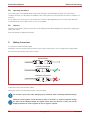
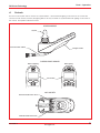
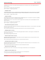
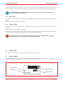
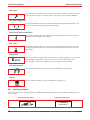
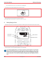
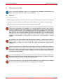
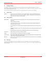
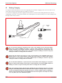
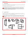
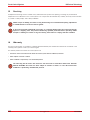
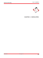
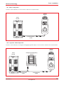
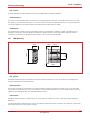
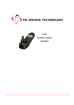
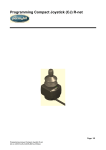
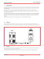
R-net - Operation
PG Drives Technology
1
Introduction
The relevant contents of this chapter should be included in the wheelchair operating guide. Further copies are available
from PGDT in either written or disk (Adobe PDF) format. Copies should not be made without the express permission of PG
Drives Technology.
The operation of the R-net varies dependent on programming. This chapter covers all types of operation. It is the
responsibility of the wheelchair manufacturer to ensure that only the relevant sections of this chapter are included in the
wheelchair’s operating manual.
The operation of the R-net wheelchair control system is simple and easy to understand. The control system incorporates
state-of-the-art electronics, the result of many years of research, to provide you with ease of use and a very high level of
safety. In common with other electronic equipment, correct handling and operation of the unit will ensure maximum
reliability.
Please read this chapter carefully - it will help you to keep your wheelchair reliable and safe.
2
General
An R-net control system comprises a minimum of two modules - Joystick Module and Power Module. Because of the
modular design, the depth of the control system can be greatly increased. The following diagram shows the basic set-up.
Joystick
Module
Power
Module
MODE
PROFILE
Communication
Cable
2.1
Handling
Avoid knocking your control system and especially the joystick. Be careful not to strike obstacles with the control system or
joystick when you drive. Never drop the control system.
When transporting your wheelchair, make sure that the control system is well protected. Avoid damage to cables.
SK77981-3
www.pgdt.com
11
R-net Control System
2.2
PG Drives Technology
Operating Conditions
Your control system uses industrial-grade components throughout, ensuring reliable operation in a wide range of
conditions. However, you will improve the reliability of the control system if you keep exposure to extreme conditions to a
minimum.
Do not expose your control system or its components to damp for prolonged periods. If the control system becomes
contaminated with food or drink clean it off as soon as possible.
2.3
Cleaning
Clean the control system and the joystick with a cloth dampened with diluted detergent. Be careful when cleaning the
joystick and screen.
Never use abrasive or spirit-based cleaners.
3
Mating Connectors
To connect the Communication Cables:
Holding the connector housing, firmly push the connector into its mate until you can no longer see the yellow plastic.
The connectors are secured using a friction system.
Disconnected
Correctly Connected
Incorrectly Connected
To disconnect the Communication Cables:
Holding the connector housing firmly, pull the connectors apart.
Do not hold or pull on the cable. Always grip the connector when connecting and disconnecting.
When the control system is first switched on after a connection, or system component change
the Timer will be displayed whilst the system checks itself and then the re-start icon will be
displayed. Switch the control system off and on again to operate.
12
www.pgdt.com
SK77981-3
R-net - Operation
PG Drives Technology
4
Controls
The R-net control system has two versions of Joystick Module – with and without lighting control. Most of the controls are
common to both versions, however, the lighting buttons are only included on Joystick Module with lighting control. Each of
the controls are explained within this section.
JOYSTICK MODULE
Joystick
Communication Cable
Charger Socket
CONTROL PANEL VARIANTS
Without Lighting
With Lighting
LCD Screen
MODE
PROFILE
MODE
PROFILE
JACK SOCKETS
External On/Off Switch Jack
External Profile Switch Jack
SK77981-3
www.pgdt.com
13
R-net Control System
4.1
PG Drives Technology
Joystick
The primary function of the joystick is to control the speed and direction of the wheelchair. The further you push the joystick
from the center position the faster the wheelchair will move. When you release the joystick the brakes are automatically
applied.
If the wheelchair is fitted with actuators, the joystick can also be used to move and select actuators, refer to section 3.8 for
more details.
4.2
Buttons
BUTTONS
Horn Button
On/Off Button
MODE
Mode Button
Speed Buttons
Decrease / Increase
PROFILE
Profile Button
Hazard Button & LED
Lights Button & LED
Left Indicator Button & LED
Right Indicator Button & LED
4.2.1 On/off Button
The on/off button applies power to the control system electronics, which in turn supply power to the wheelchair’s motors.
Do not use the on/off button to stop the wheelchair unless there is an emergency. (If you do, you may shorten the life of
the wheelchair drive components).
4.2.2 Horn Button
The Horn will sound while this button is depressed.
4.2.3 Speed Decrease Button
This button decreases the maximum speed setting.
Depending on the way the control system has been programmed a momentary screen may be displayed when the
button is pressed.
Refer to section 5 for details of the momentary screen
Refer to Chapter 3 - Programming for details.
4.2.4 Speed Increase Button
This button increases the maximum speed setting.
14
www.pgdt.com
SK77981-3
R-net - Operation
PG Drives Technology
Depending on the way the control system has been programmed a momentary screen may be displayed when the
button is pressed.
Refer to section 5 for details of the momentary screen
Refer to Chapter 3 - Programming for details.
4.2.5 Mode Button
The Mode button allows the user to navigate through the available operating Modes for the control system. The available
modes are dependant on programming and the range of auxiliary output devices connected to the control system.
Refer to Chapter 3 - Programming for details.
4.2.6 Profile Button
The Profile button allows the user to navigate through the available Profiles for the control system. The number of available
Profiles is dependant on how the control system is programmed.
Depending on the way the control system has been programmed a momentary screen may be displayed when the
button is pressed.
Refer to section 5 for details of the momentary screen
Refer to Chapter 3 - Programming for details.
4.2.7 Hazard Warning Button and LED
This button activates and de-activates the wheelchairs hazard lights. Depress the button to turn the hazards on and depress
the button again to turn them off.
When activated the hazard LED and the indicator LED’s will flash in sync with the wheelchair’s indicators.
4.2.8 Lights Button and LED
This button activates and de-activates the wheelchairs lights. Depress the button to turn the lights on and depress the
button again to turn them off.
When activated the lights LED will illuminate.
4.2.9 Left Indicator Button and LED
This button activates and de-activates the wheelchair’s left indicator. Depress the button to turn the indicator on and
depress the button again to turn it off.
When activated the left indicator LED will flash in sync with the wheelchair’s indicator.
4.2.10 Right Indicator Button and LED
This button activates and de-activates the wheelchair’s right indicator. Depress the button to turn the indicator on and
depress the button again to turn it off.
When activated the right indicator LED will flash in sync with the wheelchair’s indicator.
4.2.11 External On/off Switch Jack
This allows the user to turn the control system on and off using an external device, such as a buddy button.
4.2.12 External Profile Switch Jack
This allows the user to select Profiles using an external device, such as a buddy button.
To change the Profile whilst driving simply press the button.
SK77981-3
www.pgdt.com
15
R-net Control System
PG Drives Technology
If the control system is set to latched drive or actuator control operation, then the polarity of the jack input is reversed to effect
a fail safe system; meaning this input will provide an External Profile Switch function and an Emergency Stop Switch function.
The Joystick Module is supplied with rubber bungs which must be inserted into the Jack Socket
when no external device is connected.
4.3
LCD Screen
The status of the control system can be understood by observing the LCD screen. The control system is on when the screen is
backlit.
Refer to section 5 for details on screen symbols.
4.4
Charger Socket
This socket should only be used for charging or locking the wheelchair. Do not connect any type of programming cable into
this socket.
Refer to section 10 for more details on charging.
This socket should not be used as a power supply for any other electrical device. Connection of other electrical devices
may damage the control system or affect the E.M.C. performance of the wheelchair.
The control system’s warranty will be voided if any device other than a battery charger supplied,
with the wheelchair, or the lock key is connected into this socket.
5
LCD Screen
The status of the control system can be understood by observing the LCD screen.
5.1
Screen Symbols
The Drive screen for the R-net has common components, which will always appear, and components which will only
appear under certain conditions. Below is a view of a typical Drive screen in Profile 1.
Current Profile
Profile Name
Battery Indicator
1
Indoor-Drive
16
www.pgdt.com
Speed Indicator
SK77981-3
R-net - Operation
PG Drives Technology
5.1.1
Battery Indicator
This displays the charge available in the battery and can be used to alert the user to the
status of the battery.
Steady
This indicates that all is well.
Flashing Slowly
The control system is functioning correctly, but you should charge the battery as soon as
possible.
Stepping Up
The wheelchair batteries are being charged. You will not be able to drive the wheelchair until
the charger is disconnected and you have switched the control system off and on again.
5.1.2 Speed Indicator
This displays the current speed setting.
The speed setting is adjusted using the Speed Buttons.
5.1.3 Current Profile
1
Indoor-Drive
The Profile Number describes which Profile the control system is currently operating in.
The Profile Text is the name or description of the Profile the control system is currently operating
in.
5.1.4 In Focus
When the control system contains more than one method of direct control, such as a
secondary Joystick Module or a Dual Attendant Module, then the Module that has control of
the wheelchair will display the In Focus symbol.
5.1.5 Speed Limit
If the speed of the wheelchair is being limited; for example, by a raised seat, then this symbol
will be displayed.
If the wheelchair is being inhibited from driving, then the symbol will flash.
5.1.6 Latched
When the control system is operating in a latched condition this symbol will be displayed.
5.1.7 Restart
When the control system requires a reboot; for example, after a module re-configuration, this
symbol will be flashed.
SK77981-3
www.pgdt.com
17
R-net Control System
PG Drives Technology
5.1.8 Fault
The control system can detect a wide variety of errors. When the system has detected an error
that is not severe enough to cause the system to trip, then this symbol will be displayed.
5.1.9 Motor Temperature
This symbol is displayed when the control system has intentionally reduced the power to the
motors, in order to protect them against heat damage.
5.1.10 Control System Temperature
This symbol is displayed when the control system has intentionally reduced its own power, in
order to protect itself against heat damage.
5.1.11 Timer
This symbol is displayed when the control system is changing between different states. An
example would be entering into Programming Mode. The symbol is animated to show the
sands falling.
5.1.12 E-Stop
E-STOP
If the control system is programmed for latched drive or actuator operation, then it is normal
for an Emergency Stop Switch to be connected into the External Profile Switch Jack.
If the Emergency Stop Switch is operated or disconnected, this symbol will flash.
5.1.13 Environmental
When Environmental Mode is entered the screen will display the following icon.
5.1.14 PC
When PC Mode is entered the screen will display the following icon.
5.2
Momentary Screens
If the momentary screens are programmed to be displayed then pressing the Speed or Profile Buttons will display screens
such as below.
Speed Momentary Screen
Profile Momentary Screen
Profile 2
Outdoor-Drive
18
www.pgdt.com
SK77981-3
R-net - Operation
PG Drives Technology
5.3
Diagnostic Screen
When the control system safety circuits have operated and the control system has been prevented from moving the
wheelchair a diagnostics screen will be displayed.
This indicates a system trip, i.e. the R-net has detected a problem somewhere in the wheelchair’s electrical system.
Identified Module
Trip Text
PM
Controller Fault
Trip Code
0506
If the error is in a non-active module, for example in the ISM but with a drive Profile is selected, then drive will still be
possible, however, the diagnostic screen will appear intermittently.
5.3.1 Identified Module
This identifies which module of the control system has registered the problem.
PM
Power Module
JSM
Joystick Module
ISM
Intelligent Seating/lighting Module
5.3.2 Trip Text
The Trip Text gives a brief description of the trip type.
5.3.3 Trip Code
The 4 digit code displayed gives the exact trip that has been recorded.
5.3.4 Diagnostic Procedure
Please follow this procedure:
• Read and note the Trip Text displayed, the identified Module and the Trip Code.
• Switch off the control system.
• Make sure that all connectors on the listed Module and the wheelchair are mated securely.
• Check the condition of the battery.
• Find the definition of the Trip Code in the Service Guide, and take the required action.
• Switch on the control system again and try to drive the wheelchair. If the safety circuits operate again, switch off and
do not try to use the wheelchair. Contact your service agent.
SK77981-3
www.pgdt.com
19
R-net Control System
PG Drives Technology
Example:
PM
Low Battery
Identified Module
Power Module Trip.
Trip Text
Low Battery
Trip Code
2C00
2C00
This means the battery needs charging or there is a bad connection to the battery.
• Check the connections to the battery. If the connections are good, try charging the battery.
5.4
Locking the Control System
The Control System can be locked in one of two ways. Either using a button sequence on the keypad or with a physical
Key. How the Control System is locked depends on how the wheelchair manufacturer has programmed the system.
5.4.1 Keypad Locking
To lock the wheelchair using the keypad.
• While the control system is switched on, depress and hold the On/off button.
• After 1 second the control system will beep. Now release the On/off button
• Deflect the joystick forwards until the control system beeps.
• Deflect the joystick in reverse until the control system beeps.
• Release the joystick, there will be a long beep.
• The wheelchair is now locked.
The following screen will be displayed.
20
www.pgdt.com
SK77981-3
R-net - Operation
PG Drives Technology
To unlock the wheelchair
• If the control system has switched off, press the On/off button.
• Deflect the joystick forwards until the control system beeps.
• Deflect the joystick in reverse until the control system beeps.
• Release the joystick, there will be a long beep.
• The wheelchair is now unlocked.
5.4.2 Key Locking
To lock the wheelchair with a key lock.
• Insert and remove a PGDT supplied key into the Charger Socket on the Joystick Module.
• The wheelchair is now locked.
The following screen will be displayed.
To Unlock the wheelchair.
• If the control system has switched off, press the On/off button.
• Insert and remove a PGDT supplied key into the Charger Socket.
• The wheelchair is now unlocked.
5.5
Actuator Selection Screen
To adjust the seat position the actuator screen must be visible.
Depress the Mode Button to scroll through the Mode screens until you reach the actuator screen, displayed below.
Actuator adjustment is achieved as follows.
• Move the Joystick sideways to select the desired axis.
SK77981-3
www.pgdt.com
21
R-net Control System
PG Drives Technology
(This is indicated by the section of the wheelchair that is highlighted)
• Move the joystick forwards and backwards to move the actuator.
• Repeat these steps for each actuator that requires adjustment.
To drive again depress the Mode button until the Drive screen is reached.
6
•
Getting Ready to Drive
Operate the on/off switch. The screen will go through an initializing process then show the base screen as follows.
Current Profile
Profile Name
Battery Indicator
1
Speed Indicator
Profile 1
MODE
PROFILE
• Check that the Speed Setting is at a level which suits you.
• Push the joystick to control the speed and direction of the wheelchair.
If you push the joystick before or just after you switch the control system on, the screen will
flash the joystick displaced screen. You must release and center the joystick to resume normal
operation. If you do not release the joystick within five seconds the wheelchair will not be able
to move, even if you release the joystick and push it again. The screen will display the diagnostic
screen at this time. You can reset this condition by switching the control system off and on
again.
22
www.pgdt.com
SK77981-3
R-net - Operation
PG Drives Technology
If you do not push the joystick as you switch the wheelchair on and the diagnostic screen is displayed, as in the following
diagram, then the R-net has detected a problem somewhere in the wheelchair’s electrical system.
Identified Module
Trip Text
PM
Module Error
7
Tips for Using Your Control System
7.1
Driving - General
Trip Code
0506
Make sure that the control system is mounted securely and that the joystick position is correct. The hand or limb you use to
operate the joystick should be supported, for example by the wheelchair arm pad. Do not use the joystick as the sole
support for your hand or limb - wheelchair movements and bumps could upset your control.
7.2
Driving Technique
The control system interprets your joystick movements and produces appropriate movements of your wheelchair. You will
need very little concentration to control the wheelchair, which is especially useful if you are inexperienced. One popular
technique is to simply point the joystick in the direction you want to go. The wheelchair will “home-in” on the direction you
push the joystick.
The further you push the joystick away from the rest position, the faster the wheelchair will go. Releasing the joystick will stop
the wheelchair.
The intelligent speed control system minimizes the effects of slopes and different types of terrain.
The wheelchair user must be capable of driving a wheelchair safely. PGDT accepts no liability
for losses of any kind arising from failure to comply with this condition.
7.3
Slow or sluggish movement
If the wheelchair does not travel at full speed or does not respond quickly enough, and the battery condition is good,
check the maximum speed setting. If adjusting the speed setting does not remedy the problem then there may be a nonhazardous fault. Contact your service agent.
SK77981-3
www.pgdt.com
23
R-net Control System
8
PG Drives Technology
Precautions for Use
In the event of the wheelchair moving in an unexpected way RELEASE THE JOYSTICK. This
action will stop the wheelchair under any circumstances.
8.1
Hazards
Do not drive the wheelchair:
• Beyond restrictions indicated in your wheelchair user manual, for example maximum inclines, curb height etc.
• In places or on surfaces where a loss of wheel grip could be hazardous, for example on wet grassy slopes.
• If you know that the control system or other crucial components require repair.
Although the R-net control system is designed to be extremely reliable and each unit is rigorously
tested during manufacture, the possibility of a system malfunction always exists (however
small the probability). Under some conditions of system malfunction the control system must
(for safety reasons) stop the chair instantaneously. If there is any possibility of the user falling
out of the chair as a result of a sudden braking action, it is imperative that a restraining device
such as a seat belt is supplied with the wheelchair and that it is in use at all times when the
wheelchair is in motion. PGDT accept no liability for losses of any kind arising from the unexpected
stopping of the wheelchair, or arising from the improper use of the wheelchair or control
system.
Do not operate the control system if the chair behaves erratically, or shows abnormal signs of
heating, sparks or smoke. Turn the control system off at once and consult your service agent.
PGDT accepts no liability for losses of any kind arising from failure to comply with this
condition.
Electronic equipment can be affected by Electro Magnetic Interference (EMI). Such interference
may be generated by radio stations, TV stations, other radio transmitters and cellular phones.
If the chair exhibits erratic behavior due to EMI, turn the control system off immediately and
consult your service agent. PGDT accepts no liability for losses of any kind arising from failure
to comply with this condition.
It is the responsibility of the chair manufacturer to ensure that the wheelchair complies with
appropriate National and International EMC legislation. PGDT accepts no liability for losses of
any kind arising from failure to comply with this condition.
The wheelchair user must comply with all wheelchair safety warnings. PGDT accepts no liability
for losses of any kind arising from failure to comply with this condition.
24
www.pgdt.com
SK77981-3
R-net - Operation
PG Drives Technology
9
Safety Checks
The electronic circuits in your control system have been designed to be extremely safe and reliable. The on-board
microcomputer carries out safety checks at up to 100 times per second. To supplement this safety monitoring you should
carry out the following periodic checks.
If the control system fails any of these checks, do not use the wheelchair and contact your service agent.
9.1
Daily Checks
Joystick:
9.2
With the control system switched off, check that the joystick is not bent or damaged and that it
returns to the center when you push and release it. If there is a problem do not continue with the
safety checks and contact your service agent.
Weekly Checks
Parking brake:
This test should be carried out on a level floor with at least one meter clear space around the
wheelchair.
Switch on the control system.
Check that the screen remains on, after initialization and that the battery gauge is displaying a
reasonable amount of charge.
Push the joystick slowly forwards until you hear the parking brakes operate. The chair may start to
move.
Immediately release the joystick. You must be able to hear each parking brake operate within a few
seconds.
Repeat the test a further three times, pushing the joystick slowly backwards, left and right.
Connectors:
Make sure that all connectors are securely mated.
Cables:
Check the condition of all cables and connectors for damage.
Joystick gaiter:
Check the thin rubber gaiter or boot, around the base of the joystick shaft, for damage or splitting.
Check visually only, do not handle the gaiter.
Mounting:
Make sure that all the components of the control system are securely mounted. Do not overtighten
any securing screws.
9.3
Servicing
To ensure continued satisfactory service, we suggest you have your wheelchair and control system inspected by your
service agent after a period of 1 year from commencement of service. Contact your service agent for details when the
inspection is due.
SK77981-3
www.pgdt.com
25
R-net Control System
10
PG Drives Technology
Battery Charging
To charge the wheelchair batteries connect the charger plug into the battery charging socket on the R-net JSM. You will
not be able to drive the wheelchair when the charger is connected.
To connect the charger plug, ensure the single pin is at the bottom, as shown in the following illustration, then offer the
charger plug to the R-net in a horizontal orientation. The molded guide on the R-net will help you to locate the plug. Ensure
the plug is pushed fully in position.
Charger
Plug
Charger Socket
Single Pin
to bottom
Do not exceed the maximum charging current of 12 A rms. Always use an off-board charger
fitted with a Neutrik NC3MX plug. Failure to observe these conditions could result in poor
contact resistance in the charger connector resulting in overheating of the charger plugs. This
presents a potential burn hazard for the user. PGDT accepts no liability for losses of any kind
arising from failure to comply with this condition.
Ensure that the charger plug pins are of the correct polarity to be compatible with the pin
polarity shown on the control system’s specific data sheet. Failure to observe this condition
could result in a burn hazard or fire hazard. PGDT accepts no liability for losses of any kind
arising from failure to comply with this condition.
Do not disconnect batteries or open-circuit the circuit breaker while charging is in progress.
Failure to observe this condition could result in a burns hazard or fire hazard. PGDT accepts no
liability for losses of any kind arising from failure to comply with this condition.
Only use the battery charger that has been supplied with your wheelchair. The use of incorrect
chargers could damage the batteries, wheelchair, control system or charger itself, or may result
in parts overheating creating the potential for burns or even fire. PGDT accepts no liability for
losses of any kind if the charger is incompatible with the control system (see Chapter 2, section
7) or any other part of the wheelchair system.
26
www.pgdt.com
SK77981-3
R-net - Operation
PG Drives Technology
11
Programming
The control system can be programmed to meet your needs. Programming can be performed using the OBP (On-board
Programming) feature or the specialist R-net software and Dongle.
If you re-program your control system, make sure that you observe any restrictions given in your wheelchair user manual.
Note any changes you make for future reference.
Programming should only be conducted by healthcare professionals with in-depth knowledge of
PGDT electronic control systems. Incorrect programming could result in an unsafe set-up of a
wheelchair for a user. PGDT accepts no liability for losses of any kind if the programming of the
control system is altered from factory pre-set values.
12
Joystick Knobs
The knob fitted to your joystick is suitable for most applications. If you would prefer another type, there is a range of
alternatives available. Please contact your wheelchair distributor or manufacturer for advice. Do not replace the joystick
knob with any unauthorized item - it may cause hazardous operation.
Do not replace the joystick knob with any unauthorized item It may cause hazardous operation.
PGDT accepts no liability for losses of any kind arising from failure to comply with this
condition.
STANDARD
S30
CHIN
C38
Ø24
Ø22
Ø38.1
MUSHROOM
M48
BALL
B38
Ø48
Ø38
36
80
45
30
25.4
STICK
S80
Ø22
80
44
Ø70
Ø18
Ø16
NOTE: KNOBS MARKED
ARE TO BE MOUNTED
IN A VERTICAL ORIENTATION ONLY.
SK77981-3
T-BAR
T80
www.pgdt.com
SOFT BALL
SB70
27
R-net Control System
13
PG Drives Technology
Servicing
All repairs and servicing must be carried out by authorized service personnel. Opening or making any unauthorized
adjustments or modifications to the control system or its components will invalidate any warranty and may result in hazards
to yourself or other people, and is strictly forbidden.
PGDT accept no liability for losses of any kind arising from unauthorized opening, adjustment
or modifications to the R-net control system.
If the control system is damaged in any way, or if internal damage may have occurred through
impact or dropping, have the product checked by qualified personnel before operating. PGDT
accepts no liability for losses of any kind arising from failure to comply with this condition.
14
Warranty
The R-net control system is covered by a warranty period defined by the wheelchair manufacturer. For details of the
warranty period, please contact your service agent.
The warranty will be void if the R-net control system has:
•
Not been used in accordance with the R-net control system Technical Manual, SK77981.
•
Been subject to misuse or abuse.
•
Been modified or repaired by non-authorized persons.
The warranty will be void if the R-net has not been used in accordance with R-net Technical
Manual SK77981, the R-net has been subject to misuse or abuse, or if the R-net has been
modified or repaired by unauthorized persons.
28
www.pgdt.com
SK77981-3
R-net - Installation
PG Drives Technology
CHAPTER 2 - INSTALLATION
SK77981-3
www.pgdt.com
29
R-net Control System
30
PG Drives Technology
www.pgdt.com
SK77981-3
R-net - Installation
PG Drives Technology
1
1.1
Documentation
R-net Operation
Study Chapter 1. It is important that the operation information in Chapter 1 is supplied with the wheelchair, either as part of
the wheelchair user handbook or as a separate document.
This Chapter sets out the installation conditions that must be complied with in order to meet the safety requirements of TÜV
(Germany), ISO7176-14 and EN12184.
1.2
Program Settings
The R-net control system is supplied with preset settings that are chosen with the wheelchair manufacturer to ensure safe
operation and compliance with relevant legal requirements, over the whole of the operating range of the wheelchair.
It is the manufacturer’s responsibility to program the control system to suit the vehicle model
and ensure safe operation in compliance with relevant legal requirements over the whole of the
operating range. PGDT accepts no liability for losses of any kind due to failure to, or incorrect
programming or the R-net Control System. Refer to Chapter 3 for programming details.
The wheelchair must stop within the maximum distance specified for the country in which the wheelchair will be used. TÜV
Product Service (Germany) specify the distance to be as stated in EN12184.
If users with particular disabilities need very low braking rates and this results in a longer stopping distance, the maximum
speed must be re-programmed so that the stopping distance requirement is satisfied.
State in the wheelchair user handbook that it is the responsibility of the person programming the control system to make
sure that the stopping distance requirement is satisfied. If the braking rate is low, the forward and reverse maximum speed
settings may need to be re-programmed. To assist the person in this task, include a graph in the wheelchair user
handbook showing the relationship between the maximum forward/reverse speed settings and the forward/reverse braking
rate which is required to ensure the correct stopping distance.
It may be possible to program settings which compromise the stability of the wheelchair. Perform suitable tests to establish
which programming restrictions are needed to prevent instability. State any programming restrictions in the wheelchair user
handbook.
State in the wheelchair user handbook that it is the responsibility of the person programming the control system to make
sure that the settings are safe and to note any programming changes that they make.
Programming should only be conducted by healthcare professionals with in-depth knowledge of
PGDT electronic control systems. Incorrect programming could result in an unsafe setup of a
wheelchair for the user. PG Drives Technology accepts no liability for losses of any kind if the
programming of the control system is altered from factory pre-set values. PGDT accepts no
liability for losses of any kind if the drive or stability characteristics of the chair are altered
without prior notification and discussion with PGDT.
It is possible for wheelchair manufacturers to limit the values of speeds and accelerations that
can be programmed in the field. This facility ensures a safe-operating envelope for the wheelchair
can be maintained. These limits are set in the factory by PGDT and can only be altered by PGDT.
Contact PGDT for more information.
1.3
Soft-Stop
The R-net has a programmable value called Soft Stop Rate which sets the emergency stopping distance. You must ensure
that the emergency stopping distance is within the distance specified for the country in which the wheelchair will be used.
SK77981-3
www.pgdt.com
31
R-net Control System
PG Drives Technology
TÜV Product Service (Germany) specify the distance to be as stated in EN12184.
1.4
Other Information
You must provide a diagram in the wheelchair user handbook showing the user controls and the main features of the
control system.
In addition, you should include a brief specification of operating supply voltage range and operating temperature range.
2
Immobilizing the Wheelchair
2.1
Prevention of Unauthorized Use
TÜV requires that the wheelchair must have a means of preventing unauthorized use. This can be implemented as detailed
in Chapter 1 section 5.3.
2.2
Charger Interlock
ISO 7176-14 requires you to provide a means of preventing the use of the wheelchair while the batteries are being
charged. The charger socket and on-board charger connection fitted to PGDT R-net control systems include an inhibit
facility. Refer to section 8.1.
Contact PG Drives Technology if you need advice.
The chair manufacturer is responsible for providing a means of preventing the use of the
wheelchair while the batteries are being charged. PGDT accepts no liability for losses of any
kind arising from failure to comply with this condition.
2.3
Power Down
The control system can be programmed to power down if the joystick is not operated over a set period of time. Refer to
Chapter 3 for programming details.
To restart, switch the control system on.
3
Connections
The following is a selection of the most common configurations
3.1
32
Control Configurations
www.pgdt.com
SK77981-3
R-net - Installation
PG Drives Technology
3.1.1
Basic Configuration
Consists of a Power Module, a Communication Cable and a Joystick Module.
Joystick
Module
Power
Module
MODE
PROFILE
Communication
Cable
3.1.2 Joystick & ISM Configuration
Consists of a Power Module, an Intelligent Seating/Lighting Module (ISM), 2 Communication Cables and a Joystick Module.
Joystick
Module
Power
Module
Intelligent Seating/lighting
Module
MODE
Communication
Cable
SK77981-3
PROFILE
Communication
Cable
www.pgdt.com
33
R-net Control System
PG Drives Technology
Mounting
4.1
Joystick Module Mounting
40.0mm
(HOLE CTS)
4
28.5mm
4.1.1
General
The Joystick Module should be secured using two M5 screws with a maximum penetration of 12mm. Be careful not to
overtighten the screw. See data sheet for further information.
4.1.2 Orientation
The Joystick Module must be mounted with the joystick shaft pointing vertically upwards. If you want to use any other
mounting attitudes then contact PGDT.
4.2
Power Module Mounting
CL
1 66.0mm 6.5"
(HOLE CTS)
34
www.pgdt.com
SK77981-3
R-net - Installation
PG Drives Technology
4.2.1 General
Fix the Power Module to the wheelchair chassis using suitable M5 or equivalent hardware.
4.2.2 Orientation
The function of the Power Module is not sensitive to mounting orientation; however, it should be mounted in such a way
that water cannot enter and remain in the connector recesses. It is recommended that the unit is not mounted with the
connectors uppermost. The Power Module has an IPX4 dust and water resistance rating.
4.2.3 Position
The Power Module must be mounted in a position where it is not exposed to conditions of water or dust above those
specified in ISO7176/9. The Power Module is designed to withstand levels of shock and vibration experienced when
mounted to the chassis of a wheelchair. Direct impacts onto the unit should be avoided.
4.3
ISM Mounting
33mm
65mm
45mm
3
4
1
2
LIGHTS
104mm
5
6
INH
42mm
105mm
4.3.1 General
The ISM should be secured using four M5 screws with a maximum penetration of 7mm. Be careful not to overtighten the
screw. See data sheet for further information.
4.3.2 Orientation
The function of the ISM is not sensitive to mounting orientation; however, it should be mounted in such a way that water
cannot enter and remain in the connector recesses. It is recommended that the unit is not mounted with the connectors
uppermost. The ISM has an IPX4 dust and water resistance rating.
4.3.3 Position
The ISM must be mounted in a position where it is not exposed to conditions of water or dust above those specified in
ISO7176/9.
The ISM is designed to withstand levels of shock and vibration experienced when mounted to the chassis of a wheelchair.
Direct impacts onto the unit should be avoided.
SK77981-3
www.pgdt.com
35
R-net Control System
4.4
PG Drives Technology
Cables
The cables to the ISM must be routed and secured in such a way as to prevent damage to them, for example by cutting
or crushing.
Contact PGDT if you need further advice.
5
Joystick Module Wiring
The Joystick Module is connected to the Power Module with a Communication Cable.
To connect the Communication Cables:
• Holding the connector housing, firmly push the connector into its mate until you can no longer see the yellow plastic.
The connectors are secured using a friction system.
Disconnected
Correctly Connected
Incorrectly Connected
To disconnect the Communication Cables:
• Holding the connector housing firmly, pull the connectors apart.
Do not hold or pull on the cable. Always grip the connector when connecting and disconnecting.
When the control system is first switched on after a connection, or system component change
the Timer will be displayed whilst the system checks itself and then the Re-start icon will be
displayed. Switch the control system off and on again to operate.
Route and secure the cable in such a way as to prevent damage, for example by crushing or cutting.
36
www.pgdt.com
SK77981-3