1
6 720 646 148 - 11/2010 US/CA (en)
For the user
User’s Instructions
Condensing gas boiler
Logamax plus GB162-L.B. 80 kW/100 kW
This manual is available in the English and French
language.
This manual must be retained for future use.
Please read thoroughly before operating
Warning: If the information in these instructions is not followed exactly, a fire or
explosion may result causing property damage, personal injury or loss of life.
– Do not store or use gasoline or other flammable vapors and liquids in the
vicinity of this or any other boiler.
– What to do if you smell gas
• Do not try to light any boiler.
• Do not touch any electrical switch; do not use any phone in your building.
• Immediately call your gas supplier from a neighbor’s phone. Follow the gas
supplier’s instructions.
• If you cannot reach your gas supplier, call the fire department.
– Installation and service must be performed by a qualified installer,
service agency or the gas supplier.
CAUTION !
The operating manual is part of the documentation that is delivered to the installation's operator. Go through the information in this manual with the owner/operator and make sure that he or she is familiar with all the necessary operating
instructions.
http://www.buderus.net
2
Contents
1
For your safety . . . . . . . . . . . . . . . 5
4
Starting up the boiler . . . . . . . . . 18
1.1
1.2
1.3
Designated use . . . . . . . . . . . . . . . . . . 5
Safety instructions . . . . . . . . . . . . . . . . 6
Quality of the heating system water . . . 8
2
Lighting Instructions . . . . . . . . . . . 9
4.1
4.2
4.3
4.4
Boiler settings . . . . . . . . . . . . . . . . . . . 18
Check the system pressure . . . . . . . . . 19
Fill the heating system . . . . . . . . . . . . 20
Frost protection . . . . . . . . . . . . . . . . . . 23
3
Operating the BC10 basic
controller 10
5
Shutting down the boiler . . . . . . 24
3.1
3.2
3.3
3.4
General . . . . . . . . . . . . . . . . . . . . . . .
Switching ON and OFF . . . . . . . . . . .
Setting the DHW temperature value .
Setting the space heating water
temperature
"Burner ON" LED . . . . . . . . . . . . . . . .
Other functions and economic
heating
3.5
3.6
http://www.buderus.net
11
11
12
15
17
6
Operating and error messages . 25
6.1
6.2
6.3
6.4
6.5
Normal operation menu . . . . . . . . . . . . 25
Manual Operation menu . . . . . . . . . . . 26
Settings menu . . . . . . . . . . . . . . . . . . . 28
Display codes . . . . . . . . . . . . . . . . . . . 31
Identifying and resetting faults . . . . . . 34
17
3
Preface
About these instructions
These user's Instructions contain important
information for the safe and proper operation
of Logamax plus GB162-L.B. 80kW/100kW
condensing gas boilers.
Subject to technical changes!
Changes may be made following technical
improvements!
Updating of documentation
If the information in this manual is not followed
exactly, a fire or explosion may result causing
property damage, personal injury or loss of
life.
http://www.buderus.net
Please contact us if you have any suggestions
for improvements or corrections.
4
For your safety
1
For your safety
Logamax plus GB162 L.B. condensing gas
boilers are designed and built according to the
latest technological advances and safety
requirements.
The design is specifically focused on ease of
use. To ensure the safe, economical and environmentally friendly use of the heating system
we urge you to read and observe the User's
Instructions.
1.1
Hazard definitions
A
DANGER
Indicates the presence of hazards that
will cause severe personal injury, death
or substantial property damage.
A
WARNING
Indicates the presence of hazards that
can cause severe personal injury, death
or substantial property damage.
A
CAUTION
Indicates presence of hazards that will
or can cause minor personal injury or
property damage.
H
CAUTION
Risk of electric shock.
Indicates presence of hazards due to
electric shock.
Designated use
The boiler was designed for heating water for
a central heating system and generating
domestic hot water. The boiler can be installed
either as a single system or as part of a
multiple system (cascade system) with a
maximum of 8 boilers connected together.
http://www.buderus.net
5
For your safety
I
1.2
NOTICE
Indicates special instructions on installation, operation or maintenance that
are important but not related to
personal injury or property damage.
Safety instructions
Make sure to observe these safety instructions. Failure to do so can result in property
damage, personal injury or loss of life.
– Installation, gas and flue connection,
commissioning, electrical connection and
maintenance activities must only be carried
out by a trained service provider.
– Certain work, e.g. on gas lines, may require
a professional license. Only carry out such
work if you are licensed to do so.
– Only use the boiler for its intended purpose
and only when it is in working order.
http://www.buderus.net
– Have a trained service provider check,
clean and service the heating system once
a year.
Buderus recommends a contract for annual
service and maintenance.
– The condensate collection and disposal
system must be periodically cleaned by a
trained service technician.
– Have your trained service provider give you
detailed instructions about the operation of
the heating system.
– Carefully read these user's instructions.
– Immediately have all defects to the heating
system repaired.
– Ensure that air intake and outlet openings
are open and free from obstructions at all
times.
6
For your safety
– Do not store any flammable material or
liquids in the immediate vicinity of the
boiler.
– Never use chlorinated detergents or
halogenated hydrocarbons (e.g. in
spraycans, solvents and detergents,
paints, adhesives) in the room where the
boiler is installed.
– When Calcium Chloride is present in
concrete floors (when poured in winter) it is
necessary to seal the floor with a suitable
paint.
– Do not allow too much dust to collect on the
device.
– Do not use the boiler if any part has been
under water. Immediately call a trained
service technician to inspect the boiler and
to replace any part of the control system
and any gas control which has been under
water.
http://www.buderus.net
– Should overheating occur or the gas supply
fails to shut off, do not turn off or disconnect
the electrical supply to the pump. Instead,
shut off the gas supply at a location
external to the boiler.
– The venting system must be inspected
annually. Replace any parts which show
deterioration from corrosion or any other
sources.
– This boiler does not have a pilot. It has an
ignition device which automatically lights
the burner.
– Check for smell of gas around the boiler
area. Be sure to smell next to the floor
because propane gas is heavier than air
and will settle on the floor.
– Use only your hand to turn the gas control
knob (fig. 4 on page 18). Never use tools. If
the knob will not turn by hand, don't try to
7
For your safety
repair it, call a trained service technician.
Force or attempted repair may result in a
fire or an explosion.
– When the vent system is blocked, this
boiler will shut off automatically with code
'3C'. Immediately call a trained service
technician to inspect and reset the boiler.
http://www.buderus.net
1.3
Quality of the heating system water
Use only untreated tap water when filling or
topping up the heating system. The use of
unsuitable heating system water will lead to
build-ups of sludge and corrosion, which can
in turn result in the malfunctioning of the boiler
and damage to the heat exchanger.
DO NOT treat the water with products such as
pH-adjusting substances (chemical additives)
and antifreeze or water softeners.
8
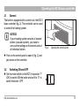
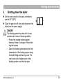
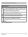
Lighting Instructions
2
Lighting Instructions
STOP!
Read the chapter "For your safety" on page 5
before lighting the boiler.
Follow the instructions to start up the boiler in
“Starting up the boiler” on page 18
A
http://www.buderus.net
9
Operating the BC10 basic controller
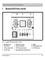
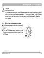
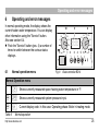
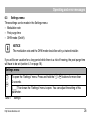
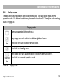
3
Operating the BC10 basic controller
10
100
110
9
120
130
90
140
11
1
8
90
888
2
3
4
110 130 150
170
190
5
6
7
1
Fig. 1
1:
2:
3:
4:
Logamatic BC10 basic controller – Controls
Main power switch
"Reset" button
"Chimney sweep" button
"Service" button
http://www.buderus.net
5:
6:
7:
8:
Service Tool connector
LED "Burner operation"
LED "Heating system status"
Space heating water temperature knob
9: Display
10: DHW temperature knob
11: LED "DHW status"
10
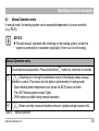
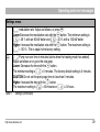
Operating the BC10 basic controller
3.1
General
The boiler is equipped with a control unit, the BC10
basic controller (fig. 2). This controller can be used
to control the heating system.
I
NOTICE
If your heating system consists of several
boilers (cascade system), you have to
carry out the settings on the control units of
all individual boilers.
Fig. 2
Opening the control panel
Push on the control panel to open it (fig. 2) and
get access to the controller.
3.2
Switching ON and OFF
Set the main switch on the BC10 to position "1"
(ON) to switch ON the boiler and set it to "0" to
switch the boiler OFF.
http://www.buderus.net
11
Operating the BC10 basic controller
H
CAUTION
Risk of electric shock.
If a hazardous situation occurs, shut OFF power to the boiler using the emergency shutoff
switch or the boiler circuit breaker (see chapter 4 "Starting up the boiler", page 18). Make
yourself familiar with the location of the emergency shutoff switch and the boiler loop
circuit breaker.
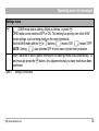
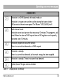
3.3
Setting the DHW temperature value
Check the local code for the max. DHW temperature.
Turn the "DHW temperature" rotary knob to set
the desired temperature of the hot water in the
DHW tank.
http://www.buderus.net
110
100
90
120
130
140
12
Operating the BC10 basic controller
0
Eco 1
Condition
Explanation
LED
OFF
No hot water supply (only heating mode).
OFF
Economy mode,
Hot water temperature
140 °F (60 °C)
The DHW will only be reheated to 140 °F (60 °C),
if the temperature has signifcantly fallen. This
reduces the number of burner starts and saves
energy. As a result the water may be a bit cooler
initially.
ON 2
The temperature set on the BC10 is a fixed
temperature that cannot be changed using a
RC thermostat.
ON 2
The temperature setting defaults to the maximum
DHW temperature of 140 °F (60 °C).
ON 2
86 – 140 Direct setting on BC10
in °F
Aut
Table 1
Entry via thermostat
(presetting)
Settings of "DHW temperature" knob
1
This function has been optimized for boilers with combined DHW heating (combi-units).
2 The LED under the rotary knob lights if the DHW temperature is below the target value (heat request for
DHW).
http://www.buderus.net
13
Operating the BC10 basic controller
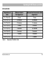
Anti-scald table
Temperature of
water
Minimum time for
first degree burn
Minimum time for second or third
degree burn
111 °F (44 °C)
5 hours
7 hours
116 °F (47 °C)
35 minutes
45 minutes
118 °F (48 °C)
10 minutes
14 minutes
122 °F (50 °C)
1 minute
5 minutes
131 °F (55 °C)
5 seconds
25 seconds
140 °F (60 °C)
2 seconds
5 seconds
149 °F (65 °C)
1 second
2 seconds
158 °F (70 °C)
–
1 second
Table 2
Temperature/Time/Burn Chart
http://www.buderus.net
14
Operating the BC10 basic controller
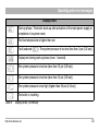
3.4
Setting the space heating water
temperature
Turn the "space heating water temperature" knob
to set the upper limit value of the heater water for
the heating operation. This limitation does not
apply to DHW preparation.
110
90
130
150
170
190
http://www.buderus.net
15
Operating the BC10 basic controller
0
Condition
Explanation
LED
OFF
No supply to heating system (only DHW heating
operation).
OFF
86 – 190 Direct setting on
BC10 in °F
Aut
Table 3
1
Entry via thermostat
(presetting)
The temperature set on the BC10 acts as a high limit. ON 1
With a AM10 or RC10 control, the water temperature
will be at a equal or lesser value. With a On/Off
thermostat the water temperature will always be the
set temperature. Supply temperature never rises
above the set temperature.
The temperature high limit setting defaults to the
ON 1
maximum boiler water temperature of 180 °F (82 °C).
Settings of "space heating water temperature" rotary knob
The LED under the rotary knob lights when the heating system is switched ON and heat is requested.
In summer mode the heating system is switched OFF (LED OFF).
http://www.buderus.net
16
Operating the BC10 basic controller
3.5
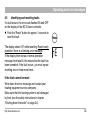
"Burner ON" LED
The LED indicates the operating condition of the
burner.
LED
Condition
ON
Burner active The water in the boiler is being heated.
OFF
Burner OFF
Table 4
3.6
Explanation
The water in the boiler has reached the required temperature or
there is no heat request.
LED indication
Other functions and economic heating
The functions described above are basic functions, carried out directly on the boiler using the
BC10 basic controller.
http://www.buderus.net
17
Starting up the boiler
4
Starting up the boiler
4.1
Boiler settings
Turn the "space heating water temperature" and
"DHW temperature" rotary knobs to "Aut" (automatic mode).
The control unit will now take control.
Slowly open the gas valve by pushing on the gas
valve and turning it ¼ rotation in an counterclockwise direction (fig. 3, pos. 1). The gas valve is
open when it is in its vertical position.
Open the pump group isolating valves (fig. 3,
pos. 2).
110
100
90
110
120
130
140
+
90
130
150
170
190
1
2
Fig. 3
http://www.buderus.net
Opening gas- and isolating valves
18
Starting up the boiler
Set the main switch on the basic controller to
position "1" (ON). The basic controller checks the
current system status and the burner becomes
operational as soon as there is a heat request.
This procedure takes approx. 30 seconds.
Adjust the settings on the control unit (see the
Operating Instructions for the control unit).
4.2
Check the system pressure
If the heating system has just been filled, the system
pressure must initially be checked every day, for
1 week.
The maximum pressure in the heating system,
measured directly at the boiler, must not exceed
51 psi (3.5 bar).
Press the "Service" button (fig. 1, pos. 4) until the
system pressure ("P22") is shown in the display
(pos. 9).
http://www.buderus.net
19
Starting up the boiler
Fill the heating system if the system pressure
has dropped below 15 psi (1.0 bar) according
to paragraph “Fill the heating system” on
page 20.
4.3
Fill the heating system
Remove the lower casing from the pump group
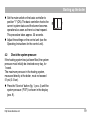
(fig. 4).
Fig. 4
http://www.buderus.net
Removing the lower casing
20
Starting up the boiler
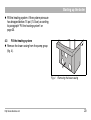
Unscrew the sealing cap (fig. 5).
Fig. 5
http://www.buderus.net
Removing cap from drain cock
21
Starting up the boiler
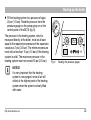
Fill the heating system to a pressure of appx.
20 psi (1.5 bar). Read the pressure from the
pressure gauge on the pump group or on the
control panel of the BC10 (fig. 6).
The pressure in the heating system, which is
measured directly at the boiler, must be at least
equal to the required pre-pressure of the expansion
vessel plus 7 psi (0.5 bar). The minimum pressure
must not be less than 15 psi (1.0 bar) (if the heating
system is cold). The maximum pressure in the
heating system must not exceed 50 psi (3.5 bar).
I
20 30
10
psi
100
110
120
130
90
140
P22
90
110 130 150
170
190
1
Fig. 6
Reading the pressure gauge
NOTICE
It is very important that the heating
system is now purged, since all air will
collect at the highest point of the heating
system when the system is slowly filled
with water.
http://www.buderus.net
22
Starting up the boiler
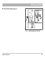
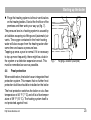
Purge the heating system via the air vents/valves
on the heating bodies. Start at the first floor of the
premises and then work your way up (fig. 7).
The pressure loss in a heating system is caused by
air bubbles escaping via fittings and (automatic) air
vents. The oxygen contained in the fresh heating
water will also escape from the heating water after
some time and cause a pressure loss.
Topping up once a year is normal. If it is necessary
to top up more frequently, there might be a leak in
the system or a defective expansion vessel. This
must be remedied as soon as possible.
4.4
Fig. 7
Purging a radiator (example)
Frost protection
When switched on, the boiler has an integrated frost
protection system. This means that no further frost
protection facilities should be installed on the boiler.
The frost protection switches the boiler on at a flow
temperature of 45 °F (7 °C) and off at a flow temperature of 59 °F (15 °C). The heating system itself is
not protected against frost.
http://www.buderus.net
23
Shutting down the boiler
5
Shutting down the boiler
Set the main switch on the basic controller to
position "0" (OFF).
Close the gas shut-off valve and disconnect the
boiler from the power supply.
A
DANGER
The heating system may freeze if it is not
operational in times of freezing weather.
– Protect the heating system against
freezing if there is a danger of frost affecting the system.
– Drain the heating system water from the
lowest point of the heating system using
the boiler filling and draining cock. The
vent screw at the highest point of the
heating system must then be open.
http://www.buderus.net
24
Operating and error messages
6
Operating and error messages
In normal operating mode, the display shows the
current heater water temperature. You can display
other information using the "Service" button.
Also see section 6.4.
Push the "Service" button (pos. 4) a number of
times to switch between the various status
displays.
10
100
110
9
120
130
90
140
11
1
8
90
888
2
3
4
110 130 150
170
190
5
6
7
1
6.1
Normal operation menu
Fig. 8
Basic controller BC10
Normal Operation menu
e
e
Table 5
[\/2/4|
Shows currently measured space heating water temperature in °F.
[p/2/2|
Shows currently measured system pressure in psi.
[-/h/\|
Current display code. In this case: Operating phase: Boiler in heating mode.
Normal operation
http://www.buderus.net
25
Operating and error messages
6.2
Manual Operation menu
In manual mode, the heating system can be operated independent of a room controller
(e. g. RC35).
NOTICE
Re-start manual operation after switching on the heating system, so that the
system is permanently in operation (especially if there is a risk of freezing).
I
Manual Operation menu
To activate manual operation: Press and hold the d button for more than 5 seconds.
d
[\/2/4} A flashing dot in the right-hand bottom corner of the display shows manual
operation is active. This means that the boiler is permanently in heating mode:
– Space heating water temperature is as set on the BC10 basic controller.
– The LED "Heating system status" lights.
– DHW mode is possible during manual operation.
e
[p/1.6} Shows currently measured system pressure in psi(pounds per square inch).
Table 6
Manual operation
http://www.buderus.net
26
Operating and error messages
Manual Operation menu
e
[-/h/\} Display code: Operating phase: Also see section 6.4. The boiler is in manual
operation mode. During manual operation the "Settings" menu (table 7 from step 2) can
be used to temporarily change the target boiler performance.
Notice: If the boiler output has been changed temporarily, this must be set again after
ending manual operation, according to the "Settings" menu (table 7).
e
[\/2/4}Shows currently measured space heating water temperature in °F.
After a power interruption manual operation ends automatically.
To end manually press and hold the d button for more than 2 seconds until the dot
disappears.
Table 6
Manual operation (continued)
http://www.buderus.net
27
Operating and error messages
6.3
Settings menu
Three settings can be made in the Settings menu:
– Modulation rate
– Post purge time
– DHW mode (On/off).
I
NOTICE
The modulation rate and the DHW mode should be set by a trained installer.
If you will be on vacation for a long period while there is a risk of freezing, the post purge time
will have to be set (section 4.1 on page 18).
Settings menu
d
e
Table 7
To open the "Settings" menu: Press and hold the d+ e buttons for more than
2 seconds.
[l/?/?| This shows the "Settings" menu is open. You can adjust the setting of this
parameter.
Settings
http://www.buderus.net
28
Operating and error messages
Settings menu
[l/?/?| modulation rate. Adjust as follows, or press e:
Lower:Decrease the modulation rate with the c button. The minimum setting is
[l/3/6| = 36 % with an 80-kW boiler and [l/3/0| = 30 % with a 100-kW boiler.
Higher: Increase the modulation rate with the d button. The maximum setting is
[l/?/?| = 100 %. This is equal to the factory setting.
e
Table 7
[f/\/5| Pump run-over time in minutes (starts when the heating mode has ended).
Adjust as follows or or go to the next step:
Lower: Decrease the time with the c button.
The minimum setting is [f/\/0| = 0 minutes. The factory default setting is 5 minutes.
CAUTION Do not set the post purge time to less than 5 minutes.
Higher: Increase the time with the d button.
The maximum setting is [f/6/0| = 60 minutes or [f/1/d| = 24 hours.
Settings (continued)
http://www.buderus.net
29
Operating and error messages
Settings menu
e
[c/\/1| DHW mode status setting. Adjust as follows, or press e:
DHW mode can be switched OFF or ON. This setting has priority over other DHW
mode settings, such as those made on the room thermostat.
Set the DHW mode with the c or d buttons. [c/\/1| means "ON", [c/\/0| means "OFF".
NOTE: Setting [c/\/0| also switches OFF the hot water cylinder frost protection.
After 5 seconds or after a power interruption the settings menu ends automatically. To
end manually press the e button. Any adjustments that you have made have been
confirmed.
Table 7
Settings (continued)
http://www.buderus.net
30
Operating and error messages
6.4
Display codes
The display shows the condition of the boiler with a code. The table below shows normal
operation codes. If a different code shows, please refer to section 6.5, "Identifying and resetting
faults" on page 34 .
Display codes
[\/-/\|
[-/a/\]
dot
Communication test while starting up.
Any display code with a dot in the bottom right-hand corner.
The boiler is in flue gas test or service mode.
[-/h/\|
The boiler is in heating mode.
[-/h/}
Any display code with a flashing dot in the bottom right-hand corner.
flashing
dot
Table 8
The boiler is in manual operation mode.
Display codes
http://www.buderus.net
31
Operating and error messages
Display codes
[=/h/\|
The boiler is in DHW (domestic hot water) mode, or
The boiler is in pump run-over time via the external hot water cylinder
130 seconds at the minimum speed. The "Burner" LED (On/Off) is off.
[0/a/\|
Boiler interval circuit.
The boiler cannot start-up more than once every 10 minutes. This program is activated if there has been a DHW request from an RC regulator more frequently
than once every 10 minutes.
[0/c/\|
The boiler prepares for a burner start-up.
There is a current heat demand or a DHW request.
[0/e/\|
The boiler is standby.
There is a current heat demand, but too much energy has been supplied.
[0/h/\|
The boiler is standby. There is no current heat demand.
[0/l/\|
Ignition phase. The gas valve is activated.
Table 8
Display codes (continued)
http://www.buderus.net
32
Operating and error messages
Display codes
[0/u/\|
Start-up phase. The boiler starts up after activation of the main power supply or
completion of a system reset.
[0/y/\|
The flow temperature is higher than set.
[2/e/\|
Fault (subcode [2/0/7|). The system pressure is too low (less than 3 psi (0.2 bar)).
[8/8/8|
Display test during start-up phase (max. 1 second).
[h/\/7|
The system pressure is too low (less than 12 psi (0.8 bar)).
[h/\/7|
The system pressure is too low (less than 12 psi (0.8 bar)).
[p/?/?|
The system pressure is too high (higher than 58 psi (4.0 bar)).
[\/r/e|
Table 8
The boiler is resetting.
Display codes (continued)
http://www.buderus.net
33
Operating and error messages
6.5
Identifying and resetting faults
If a fault occurs, the error code flashes ON and OFF
on the display of the BC10 basic controller.
Push the "Reset" button for approx. 5 seconds to
reset the fault.
The display shows "rE" while resetting. Reset is only
possible if there is a flashing error message.
If the display then shows a normal operation
message from tabel 8, this means that the fault has
been remedied. If the fault recurs, you must repeat
resetting two or three more times.
If the fault cannot be reset:
Write down the error message and contact your
heating equipment service company.
Make sure that the heating system is not damaged
by frost (see the safety instructions in chapter
“Shutting down the boiler” on page 24).
http://www.buderus.net
34
Notes
http://www.buderus.net
35
6720646148 0001
Bosch Thermotechnology Corporation
50 Wentworth Ave
Londonderry, NH 03053
Tel: (603)-552-1100 Fax: (603)-421-2719
Toll Free: 1-800-BUDERUS
www.buderus.net