1
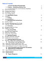
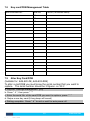
USER GUIDE
KAS-820-DE
KAS-830-RDE
1
Verison: UG_V002
kas.com.au
Discover the eTouch Remote Control Keyless Lock
Thank you for choosing KA Security’s eTouch Remote Control Keyless
Lock. As you’ll soon discover, this stylish electronic touch screen lock
represents the next generation in security by combining four methods of
access for added security and convenience - choose from pin code,
keycard, FOB or remote control.
The eTouch Remote Control Keyless Lock is battery operated, allowing
extra features that add to the lock’s usability - it emits audible and visual
confirmation of lock activation, while its blue backlit screen enables
improved keypad visibility night or day.
This user manual contains vital information to ensure this product is
operated safely and to its fullest potential. Be sure to read instructions
completely before installing or using this product.
e-Touch Technical Parameters
Category
Normal power
supply
List
Normal voltage
Description
DC 6V (4 x AAA Bat.)
Battery life
Over 3000 Times (or 12
months in standby)
5.0V 0.2V
Alarm voltage
Power
consumption
Emergency power supply
9V (DC)
Standby current (without remote) <50 uA
Standby current (with remote)
<80 uA
Pin code
Normal current
Pin code capacity
<200mA
8 pin codes (3 to 6 digits)
Temperature
Humidity
Key card/FOB capacity
Remote capacity
Normal voltage
-100 -> +500
15%~95%
80
8 remotes
3V- Lithium (1 x CR2032)
Working
environment
Key card/FOB
Remote
controller
2
Verison: UG_V002
kas.com.au
Table of Contents
2.1
2.2
2.3
2.4
3.1
4.1
5.1
5.2
5.3
6.1
6.2
7.1
7.2
7.3
8.1
8.2
9.1
10.1
10.2
10.3
12.1
12.2
12.3
2 4
4
e-Touch Technical Parameters
1 Preface - Guidelines Before Use
2 e-Touch Electronic Lock Features/ Systems
Panic Exit Function
Tamper Alert Alarm
Automatic Locking
Low Voltage alarm
3 Installation Guide
Lineation
4 Drilling
Lock Installation
5 Management Instructions
Factory Reset
Program Management Pin Code
Log into “Settings Management”
6 Pin Code
Program User Pin Code
Delete Pin Code
7 Key Card/FOB
Program Key Card/FOB
Alter Key Card/FOB
Delete Key Card/FOB
8 Remote Control
Program Remote Controller
Delete Remote Controller
9 Passage Mode Function
Activate/ Deactivate Passage Mode
10 Unlocking/ Locking Operation
Using Pin Code To Open The Lock
Using Key Card/FOB To Open The Lock
Using Remote Control To Open The Lock
11 Lock Operation and Technical Information
12 Replacement Of Batteries
Use Of External Backup Power
Refresh Switch
Default Switch
13 Figure Diagrams
3
Verison: UG_V002
5
5
8
9
9
11
12
12
13
13
14
kas.com.au
1
1.1
1.2
1.3
1.4
1.5
1.6
1.7
1.8
Preface - Guidelines Before Use
Electronic locks are sensitive and advanced products with fragile microchips and hardware. Please be aware that the position and type of
environment the lock is installed in can affect its lifespan
To install the lock, we recommend professional carpenters or builders.
Incorrect installation of the lock can lead to irreparable damage
After the lock is installed, please change the default management pin code
immediately and keep a record of your new code. Each management pin
code is 6 digitals long. Keep the backup mechanical keys in a safe secure
location
A low voltage alarm will sound when the 4xAAA batteries need replacing
Make sure the batteries are in the correct positive/negative terminals.
Incorrect positioning of the batteries may short circuit and permanently
damage the lock
Please read the manual carefully before use, and operate the lock in
accordance with instructions
This manual applies to all e-Touch products unless otherwise stated.
Disclaimer: Figures and characters in this manual are for manual
demonstration and may not reflect the exact type or style of each model.
We reserve the right to display any product that best demonstrates the
manual content
2
e-Touch Electronic Lock Features/ Systems
2.1 Panic Exit Function
With eTouch, doors can always be unlocked from the inside. Turn the
handle downwards to exit the door from the inside at any time
2.2 Tamper Alert Alarm
After consecutively entering a wrong pin code/using unauthorised Key
card/FOB 3 times, the lock will emit an acoustic-optic alarm and the digital
keypad and card induction will be locked for 1 minute
2.3 Automatic Locking
Once the correct code/Key card/FOB/remote is presented, the lock will
remain unlocked for 5 seconds and will lock automatically when the 5
seconds expire
2.4 Low Voltage alarm
When batteries are low, the lock will emit an acoustic-optic alarm to notify
batteries need changing
4
Verison: UG_V002
kas.com.au
3
3.1
Installation Guide
Lineation
Select your lock height, and place a marking on the door where you
want the lock to sit
• From this marking, measure out the backset *60mm or 70mm
provided with lock
• Measure out the other markings required that are provided on your
drilling template
• Do this for both sides of the door. You will be later required to drill
half way through the front side of the door, then halfway through
the backside
•
Drilling
4
•
•
•
•
4.1
•
•
Drill your 2 marked ‘back to back’ holes. It is recommended to drill
half way on each side of the wood to reduce chances of the wood
splitting
Drill out the latch hole on the side of the door
Place your latch in the hole on the door edge and mark around the
faceplate
Chisel out the faceplate markings from your door. This is required to
be 3.5mm deep
Lock Installation
Take your latch and place it in the pre-drilled hole [Image A]
Screw it into place with the 2 screws provided
5
Verison: UG_V002
kas.com.au
•
•
•
•
•
•
Ensure the rubber gasket cover is on both sides of the locks
Take the front handle and place it on the door, ensuring all screws
and holes line up. Place the wires from the lock through the rubber
gasket and through door hole to ensure no pinching of the wires
and a flush covering [Image B]
Insert spindle into the front handle ensuring it is inserted into the
lock properly. Spring end is at the back of the lock
Place the Back plate frame onto the back of the door and screw into
place [Image D]
Connect and line up the back handle to fit the spindle, screw into
place (spring should be to the back of the lock)
Gently connect the wire together [Image C]
6
Verison: UG_V002
kas.com.au
•
Place the back handle onto the metal frame; screw the 2 screws at
the base of the lock and 1 screw in the battery pack area. [Image
D]
•
•
Insert batteries
Your lock is now ready for programming, see instructions below
7
Verison: UG_V002
kas.com.au
5
Management Instructions
5.1 Factory Reset
The lock will be in factory reset with the management pin code default
‘123123’. ALL programmed data will be deleted
a. Open battery cover on the inside of the door.
b. Hold the default switch in the back plate for 3 seconds [Figure 13.3]
c. LED will illuminate and a ‘beep…’ sound will be heard.
5.2 Program Management Pin Code
This is the highest authority and has the ability to open the lock and
change/remove any other pin code, card/FOB or remote. It can only be
altered by completing the Factory Reset [5.1] or Program
management pin code [5.2].
a. Power on by touching the screen, then press " * "
b. Enter old management pin code, then press " * " (A long beep will sound)
c. Press " 0 ", then press " * "
d. Enter new management pin code, then press " * " (A long beep will sound)
e. Setting complete. Press " # " to exit or wait for auto power off
NOTE: The management pin must be 6 digits long (Any other code can be
3 to 6 digits)
5.3 Log into “Settings Management”
You will need to log into "setting management” before altering/removing
any pin codes/cards/FOB’s/remotes.
a. Power on by touching the screen, then press " * "
b. Enter management pin code, then press " * " (A long beep will sound)
c. Proceed to desired settings
8
Verison: UG_V002
kas.com.au
6
Pin Code
Pin code capacity: 8
6.1 Program User Pin Code
Pin codes can be from 3 to 6 digits long.
a. Log into “Settings Management” [5.3]
b. Press " 1 ", then press " * "
c. Enter new user pin code, then press " * " (A long beep will sound)
d. Setting complete. Press " # " to exit or wait for auto power off
6.2 Delete Pin Code
This function deletes ALL user pin codes except the management pin code
a. Log into “Settings Management” [5.3]
b. Press " 2 ", then press " * " (A long beep will sound)
c. Setting complete. Press " # " to exit or wait for auto power off
NOTE: All user pin codes deleted. Please see section [6.1] to program user
Pin code
7
Key Card/FOB
Card Capacity: 80- Please contact KAS to order extra key cards.
7.1 Program Key Card/FOB
Keep track of each key card/FOB serial number. You will need this for
future reference when altering card/FOB ID.
The serial number of the first card is ‘001’, the serial number of the second
card is ‘002’ and the serial number for the 80th card is ‘080’. You may use
the following format [7.2] to keep track of keycard serial number/ID. It is
sometimes useful to write on the key card/FOB with the Serial No. enrolled
into the lock.
a. Log into “Settings Management” [5.3]
b. Press " 3 ", then press " * ”
c. Swipe the first card/FOB over the screen (2 short beeps will sound)
Setting complete
d. Swipe next card/FOB or press " # " to exit or wait for auto power off
NOTE: You can consecutively enroll up to 80 cards/FOBs.
9
Verison: UG_V002
kas.com.au
7.2
Key card/FOB Management Table
Card Enrollment No:
Serial No:
1
st
001
2
nd
002
3
nd
003
4
nd
004
5
Card ID (i.e first/last name)
005
7.3 Alter Key Card/FOB
(Suitable for: KAS-820-DE, KAS-830-RDE)
To alter a card/FOB you must know the serial number that you want to
replace. The serial number should be 3 figures. i.e ‘001’.
a. Log into “Settings Management” [5.3]
b. Press " 4 “, then press " * ”
c. Enter the serial No. of the card/FOB you want to replace, press " * ”
d. Swipe a new key card (A long beep will sound)
e. Setting complete. Press " # " to exit or wait for auto power off
10
Verison: UG_V002
kas.com.au
7.4 Delete Key Card/FOB
(Suitable for: KAS-820-DE, KAS-830-RDE)
This process will delete all current cards/FOBs from the system. To remove
an individual card/FOB you must replace the card/FOB with a new one.
a. Log into “Settings Management” [5.3]
b. Press " 5 ”, then press " * " (A long beep will sound)
c. Setting complete. Press " # " to exit or wait for auto power off
NOTE: ALL Key cards/FOBs deleted please see section 7.1 to Program Key
cards/ FOB
8
Remote Control
(Suitable for: KAS-820-DE, KAS-830-RDE)
Remote Capacity: 8 - Please contact KAS to order extra remotes.
8.1
Program Remote Controller
a. Log into “Settings Management” [5.3]
b. Press " 6 ", then press " * "
c. LED emits blue light. Press the button once on remote controller
d. Remote controller is programed
NOTE: If you try and Program more than 8 remote controllers the lock will
exit programming mode automatically
8.2
Delete Remote Controller
This process will delete all current remote controllers from the lock. You
cannot delete individual remote controllers.
a. Log into “Settings Management” [5.3]
b. Press " 7 ", then press " * "
c. ALL Remote controllers are now removed. Press " # " to exit or wait for auto
power off
NOTE: ALL remote controllers deleted, please see section 8.1 to program
remote controller
11
Verison: UG_V002
kas.com.au
9
Passage Mode Function
Passage mode will leave the door in an “unlocked” state until mode is
deactivated. Passage mode allows access through the door without the
need for a pin code, key card/FOB or remote.
NOTE: If the lock is left in Passage Mode for a long period of time it will
signifcantly decrease battery life.
9.1 Activate/ Deactivate Passage Mode
a. Log into “Settings Management” [5.3]
b. Press “ 8 ", then press " * "
c. 6 Beeps -Identifies Passive Mode, 2 Beeps- Normal Status
10 Unlocking/ Locking Operation
From inside your door, your lock is always in an “unlocked” state, simply
rotate the handle down. From the outside, you will need to use one of the
following methods (unless in passage mode [9.0])
To lock your door, simply, push your door closed, the lock is
always in a ”locked” state from the outside. (Unless in passage mode
[9.0])
10.1 Using Pin Code To Open The Lock
a. Power on by touching the screen- blue lights on keypad screen indicates
power is on
b. Enter pin code, then press " * "
c. A beep will sound, motor engages. Now rotate handle to open the lock
10.2 Using Key Card/FOB To Open The Lock
a. Swipe any programmed Key card/FOB over the keypad
b. A beep will sound, motor engages. Now rotate handle to open the lock
10.3 Using Remote Control To Open The Lock
Remote controls can be used from up to 20 meters away without direct
view.
a. At any stage, press the remote controller
b. A beep will sound, motor engages. Now rotate handle to open the lock
12
Verison: UG_V002
kas.com.au
11 Lock Operation and Technical Information
Should you need to open your door without using electronics, a Master
Key is required
a. Insert a small pin into the hole at the back of the front handle [Figure 13.1]
b. Press out the magnetic cover and remove the front panel from the lock handle
c. Insert key into key barrel and turn
12 Replacement Of Batteries
Batteries are recommended be replaced ever 12 months. [Figure 13.2]
Replacing batteries will not loose any stored data
a. Remove battery cover by sliding it upward
b. Remove old batteries and replace with new ones
c. Replace battery cover
NOTE: Must use high quality 4 x AAA alkaline batteries.
12.1 Use Of External Backup Power
If you are ever in a situation where the batteries have run out, place and
hold a 9V alkaline battery on the terminals (DC IN port) at the bottom of
the lock [Figure 13.2]. This will power the lock momentarily so you can
enter the pin code or key card/FOB or remote to unlock the door.
12.2 Refresh Switch
The refresh switch on the rear of the front plate [Figure 13.2] will refresh
the keypad and test the motor. It will not open the lock or allow any
change to the codes/cards.
12.3 Default Switch
The default switch is located under the battery cover [Figure 13.3]. Press
and hold the default switch for 5 seconds until you hear a tone and a Red
LED is displayed. This will default your management code to “123123”
only. It will not erase any other user pin code/ car/ remoter controller.
13
Verison: UG_V002
kas.com.au
13 Figure Diagrams
13.1 Figure Mechanical Cylinder Location
13.2 Figure Base Of Front Plate
13.3 Figure Back Plate Battery Location
14
Verison: UG_V002
kas.com.au
For orders, enquiries and technical support please contact
1300 939 669
[email protected]
KAS.com.au
15
Verison: UG_V002
kas.com.au