1
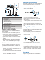
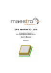
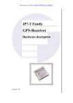
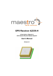
1 Turn on the chartplotter. 2 After the home screen appears, insert the memory card into Meteor™ 300 Installation Instructions NOTICE Changes or modifications not expressly approved by the party responsible for compliance could void the user's authority to operate the equipment. The Garmin Meteor device plays your media throughout your boat. It connects to your NMEA 2000® network and is controlled by your connected Garmin devices or by an optional remote control. Important Safety Information Mounting Considerations WARNING See the Important Safety and Product Information guide in the product box for product warnings and other important information. CAUTION Always wear safety goggles, ear protection, and a dust mask when drilling, cutting, or sanding. NOTICE When drilling or cutting, always check what is on the opposite side of the surface. Registering Your Device Help us better support you by completing our online registration today. • Go to http://my.garmin.com. • Keep the original sales receipt, or a photocopy, in a safe place. Contacting Garmin Product Support • Go to www.garmin.com/support and click Contact Support for in-country support information. • In the USA, call (913) 397.8200 or (800) 800.1020. • In the UK, call 0808 2380000. • In Europe, call +44 (0) 870.8501241. Loading the New Software on a Memory Card The device may contain a software-update memory card. If so, follow the instructions provided with the card. If a software update memory card is not included, you must copy the software update to a memory card. 1 Insert a memory card into the card slot on the computer. 2 Go to www.garmin.com/support/software/marine.html. 3 Select Download next to “Garmin Marine Network with SD card.” 4 Read and agree to the terms. 5 Select Download. 6 Select Run. 7 Select the drive associated with the memory card, and select Next > Finish. Updating the Device Software Before you can update the software, you must obtain a software-update memory card or load the latest software onto a memory card. July 2014 the card slot. NOTE: In order for the software update instructions to appear, the device must be fully booted before the card is inserted. 3 Follow the on-screen instructions. 4 Wait several minutes while the software update process completes. The device returns to normal operation after the software update process is complete. 5 Remove the memory card. NOTE: If the memory card is removed before the device restarts fully, the software update is not complete. CAUTION In high ambient temperatures and after extended use, the device enclosure may reach temperatures deemed dangerous to touch. Therefore the unit must be installed in a location where it will not be touched during operation. NOTICE This device should be mounted in a location that is not exposed to extreme temperatures or conditions. The temperature range for this device is listed in the product specifications. Extended exposure to temperatures exceeding the specified temperature range, in storage or operating conditions, may cause device failure. Extreme-temperature-induced damage and related consequences are not covered by the warranty. • The device must be mounted in a location where it is not submerged. • The device must be mounted in a location with adequate ventilation where it is not exposed to extreme temperatures. • The device should be mounted so that the cables can be connected easily. • To achieve IPX3 water ingress protection and optimal heat sink cooling, the device must be mounted on a vertical surface with the connectors pointing downward. • The device can be mounted on a horizontal surface, but such positioning might not achieve IPX3 water ingress protection. • To avoid interference with a magnetic compass, the device should be installed at least 203 mm (8 in.) away from a compass. Mounting the Device NOTICE If you are mounting the bracket on fiberglass with screws, it is recommended to use a countersink bit to drill a clearance counterbore through only the top gel-coat layer. This will help to avoid any cracking in the gel-coat layer when the screws are tightened. Stainless-steel screws may bind when screwed into fiberglass and overtightened. Garmin recommends applying an anti-seize lubricant to the screws before installing them. Before you mount the device, you must select a mounting location and determine the mounting hardware needed for the surface. NOTE: Mounting hardware is included with the device, but it may not be suitable for the mounting surface. 1 Place the device in the mounting location and mark the location of the pilot holes. 2 Drill the appropriate pilot hole for one corner of the device. Printed in Thailand 190-01685-02_0D 3 Loosely fasten the device to the mounting surface with one corner and examine the other three pilot-hole marks. 4 Mark new pilot-hole locations if necessary, and remove the device from the mounting surface. 5 Drill the appropriate pilot holes for the other three marks. 6 Secure the device to the mounting location. Wire Function Wire Color Notes Speaker zone 2 left (-) Green/black Speaker zone 2 right (+) Purple Speaker zone 2 right (-) Purple/black Connection Considerations Connecting to Power The device must be connected to power, either the boat ignition or an external switch, a NMEA 2000 network, speakers, and media input sources to function correctly. You should carefully plan the layout of the device, the NMEA 2000 network, the speakers, and your input sources before making any connections. When connecting the device to power, it is important to connect both power wires. The yellow power wire should be connected directly to the battery, or connected using a 15 Amp isolator switch. This provides power to the device and a constant tricklepower standby feed. The red signal wire should be connected to the same battery through the ignition or another manual switch to turn the device on and off. If it is necessary to extend the yellow power and black ground wires, use 14 AWG (2.08 mm²) wire. For extensions longer than 1 m (3 ft.), use 12 AWG (3.31 mm²) wire. If it is necessary to extend the red signal wire, use 22 AWG (0.33 mm²) wire. 1 Route the yellow power À and black ground Á wires to the battery and route the wiring-harness plug to the device. Do not connect the wiring harness to the device until all of the bare wire connections have been made. Connector Identification Connector Connects to ANT External AM/FM antenna AUX1 IN Stereo line-level RCA auxiliary source AUX2 IN Stereo line-level RCA auxiliary source ZONE 3 Separate amplifier and speakers SUB OUT Mono line-level subwoofer (tied to ZONE 3) NMEA 2000 NMEA 2000 network ACCESSORY Reserved for future use USB USB-compatible media device À Á Power and speakers Reserved for future use Wire Identification Wire Function Wire Color Notes Power (+) Yellow Ground (-) Black Ignition Red This should be connected to a separate switched 12 VDC connection, such as an ignition bus, to turn the device on and off. If you are not using a switched 12 VDC connection, you must connect this to the same source as the yellow (power) wire. Amplifier on Blue/white This is connected only when using an external amplifier on ZONE 3 (optional) Mute Brown/white When connected to ground, this mutes the audio or switches the input to AUX2. This is selectable through the settings menu. Speaker zone 1 left (+) White Speaker zone 1 left (-) White/black Speaker zone 1 right (+) Gray Speaker zone 1 right (-) Gray/black Speaker zone 2 left (+) Green 2 This should be connected to a constant 12 VDC source capable of supplying 15 Amps. 2 Connect the yellow wire to the positive (+) battery terminal, and connect the black wire to the negative (-) battery terminal. 3 Route the red signal wire  to the ignition or another manual switch Ã. NMEA 2000 Connection Considerations This device connects to a NMEA 2000 network on your boat using the included NMEA 2000 cable and connector. Through the NMEA 2000 network, you control the device using a connected Garmin device or optional remote control. If you do not have an existing NMEA 2000 network on your boat, you must create one. NOTE: The included NMEA 2000 drop cable must be used to connect the device to the NMEA 2000 network. A standard NMEA 2000 drop cable is not directly compatible with the connector on the device, although the included cable can be extended to a maximum length of 2 m (6 ft.) using a standard NMEA 2000 cable. If you are unfamiliar with NMEA 2000, you should read the “NMEA 2000 Network Fundamentals” chapter of the Technical Reference for NMEA 2000 Products. To download this document, select Manuals on the product page for your device at www.garmin.com. Installing the Remote USB Socket Before installing the USB socket, make sure the cable will reach the mounting location and the USB port on the back of the device. To allow for a proper seal, the mounting surface should be no thicker than 12 mm (½ in.). 1 Remove the nut À, the protective cover Á, and the rubber washer  from the USB socket. Item Description À Á Â Ã Ä Å Æ Ç È É Meteor 300 device Garmin device Ignition or in-line switch NMEA 2000 power cable Meteor 300 NMEA 2000 drop cable This can be extended to a maximum length of 2 m (6 ft.) using a standard NMEA 2000 cable. NMEA 2000 drop cable 12 Vdc power source NMEA 2000 terminator or backbone cable NMEA 2000 T-connector NMEA 2000 terminator or backbone cable Subwoofer Connection Considerations This device supports output to a powered subwoofer from ZONE 3 (optional). The subwoofer port on the device outputs a mono line-level signal from both RCA connectors. The port output audio level is linked to ZONE 3. • If your subwoofer amplifier has two RCA input connectors, you should connect both connectors to the device. • If your subwoofer amplifier has one RCA input connector, you can connect it to either subwoofer output RCA connector on the device, because the two RCA subwoofer outputs are parallel. • Because the subwoofer output is linked to the ZONE 3 output, you must connect the blue wire from the wiring harness to the subwoofer amplifier to provide a signal to turn it on. 2 Mark the mounting location of the USB socket and drill a 20 mm (¾ in.) hole through the mounting surface. 3 From the back of the mounting surface, insert the USB socket into the hole. To ensure proper USB-connector orientation, the flat portion of the socket à should face left when looking at the front of the socket. 4 Place the rubber washer and protective cover on the USB socket, and fasten the socket to the surface using the nut. 5 Route the USB cable to the device and connect it to the USB port. Installing the 3.5 mm Socket Before installing the 3.5 mm socket, make sure the cable will reach the mounting location and an auxiliary port on the back of the device. The cable can be extended using a standard stereo RCA extension cable if needed. To allow for a proper seal, the mounting surface should be no thicker than 15 mm (5/8 in.). 1 Remove the nut À from the 3.5 mm socket and separate it from the connected cable by pulling through one RCA connector Á at a time. ZONE 3 Connection Considerations In addition to the two stereo speaker zones available through the wiring harness, this device supports the connection to separate amplifier and speakers through the ZONE 3 port (optional). • The blue wire from the wiring harness must be connected to the amplifier to provide a signal to turn on the amplifier with the device. If it is necessary to extend this blue signal wire, use 22 AWG (0.33 mm²) wire. • The audio output is a stereo line level output over standard RCA cable. • The volume and balance for the amplifier is controlled through the interface on a connected Garmin device or through an optional Meteor remote control. 2 3 4 5 Do not remove the protective cover  from the 3.5 mm socket. Mark the mounting location of the 3.5 mm socket and drill a 20 mm (¾ in.) hole through the mounting surface. From the front of the mounting surface, feed the cable through the hole by inserting one RCA connector at a time, and pull it through until the 3.5 mm socket rests in the hole. Place the nut on the cable, thread it along the cable to the 3.5 mm socket, and fasten the socket to the surface. Route the cable to the device and connect it to an auxiliary port. Playing Media You can play and control media using a compatible Garmin chartplotter or the optional Meteor remote control. 3 1 Turn on your Meteor device, your NMEA 2000 network, your connected Garmin devices, and Meteor remote control (optional). 2 See the owner's manual for your compatible Garmin device for instructions on media playback. Go to (www.garmin.com) for additional Garmin device manuals. Auxiliary Inputs and Outputs ANT Motorola-style standard antenna connector USB USB-A industry standard USB works with iPod touch (2nd through 5th generation), iPod classic, iPod nano (4th through 7th generation), iPhone 5, iPhone 4s, iPhone 4, iPhone 3Gs, iPhone 3G SiriusXM® Satellite Radio This device can play SiriusXM satellite radio. To receive SiriusXM satellite radio, you must install a SiriusXM Connect Vehicle Tuner and have a valid subscription. Call (800) 635-2349 or go to (Shop SiriusXM Radio) for more information. The SiriusXM Connect Tuner must be connected to the accessory connector of the device, and the SiriusXM Connect Tuner must be connected to a compatible satellite radio antenna to receive signal. Locking a SiriusXM Channel Using the Meteor Remote Control 1 Select Remote Control > Unlock. 2 Enter your passcode. 3 Select Parental > Lock > Channel. 4 Select a channel. Specifications General Dimensions (L × W × H) 107 × 225 × 62 mm (4.2 × 8.9 × 2.4 in.) Weight 0.88 kg (1.96 lb.) Water resistance IPX3: Protected against spraying water when tilted up to 60 degrees vertically. Temperature Operating: from -5 to 55°C (from 23 to 131°F) Storage: from -20 to 70°C (from -4 to 158°F) Input voltage 10 to 16 Vdc NMEA 2000 LEN 1 (50 mA) Compass-safe distance 203 mm (8 in.) Audio Amplifier Output music power per channel 50 W Total output music power 200 W Total harmonic distortion (1 W output, 4 ohm load, 20 Hz 0.04 typical to 20 kHz) < 0.1% max Current (standby with ignition off) < 3 mA Current (max) 15 A Current (muted) < 800 mA Auxiliary Inputs and Outputs AUX 1 IN and AUX 2 IN RCA stereo line input for sources such as CD, DVD, and MP3. ZONE 3 RCA stereo line output SUB OUT RCA mono line output (ZONE 3) Garmin® and the Garmin logo are trademarks of Garmin Ltd. or its subsidiaries, registered in the USA and other countries. Meteor™ is a trademark of Garmin Ltd. or its subsidiaries. These trademarks may not be used without the express permission of Garmin. NMEA 2000® and the NMEA 2000 logo are registered trademarks of the National Marine Electronics Association. Apple®, the Apple logo, iPod®, iPod touch®, iPod classic®, iPod nano®, and iPhone® are trademarks of Apple Inc., registered in the U.S. and other countries. Other trademarks and trade names are those of their respective owners. Made for iPhone 5, iPhone 4s, iPhone 4, iPhone 3Gs, iPhone 3G, iPod touch (2nd through 5th generation), iPod classic, and iPod nano (4th through 7th generation). "Made for iPod and iPhone" means that an electronic accessory has been designed to connect specifically to an iPod or an iPhone respectively, and has been certified by the developer to meet Apple performance standards. Apple is not responsible for the operation of this device or its compliance with safety and regulatory standards. Please note that the use of this accessory with an iPhone may affect wireless performance. TA-2013/2178 © 2013–2014 Garmin Ltd. or its subsidiaries www.garmin.com/support