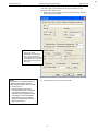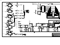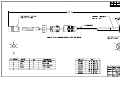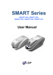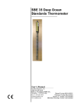
1
SBE 11plus V2 DECK UNIT For use with the SBE 9plus CTD Serial Number: 11P5745-0244 User Manual, Version 014 Sea-Bird Electronics, Inc. 13431 NE 20th Street Bellevue, Washington 98005 USA Tel: 425/643-9866 Fax:425/643-9954 This page intentionally left blank. SBE 11plus DECK UNIT OPERATING AND REPAIR MANUAL TABLE OF CONTENTS Manual Generation Date................................................................................................................... 1 Limited Liability Statement.............................................................................................................. 2 Declaration of Conformity................................................................................................................ 4 Configuration.................................................................................................................................... 5 Manual - 11plus Version 014............................................................................................................ 7 6. Appnote 11SBiospherical Surface PAR............................................................................................ 93 Appnote 68USB Ports....................................................................................................................... 95 Drawings........................................................................................................................................... 96 Warranty............................................................................................................................................ 124 Service Request Form....................................................................................................................... 127 SEA-BIRD ELECTRONICS, INC. 13431 NE 20th St. Bellevue, Washington 98005 USA Phone: (425) 643 9866 Fax: (425) 643 9954 Email: [email protected] 1 Manual Generation Date: 13 May 2011 2 LIMITED LIABILITY STATEMENT Extreme care should be exercised when using or servicing this equipment. It should be used or serviced only by personnel with knowledge of and training in the use and maintenance of oceanographic electronic equipment. SEA-BIRD ELECTRONICS, INC. disclaims all product liability risks arising from the use or servicing of this system. SEA-BIRD ELECTRONICS, INC. has no way of controlling the use of this equipment or of choosing the personnel to operate it, and therefore cannot take steps to comply with laws pertaining to product liability, including laws which impose a duty to warn the user of any dangers involved in operating this equipment. Therefore, acceptance of this system by the customer shall be conclusively deemed to include a covenant by the customer to defend, indemnify, and hold SEA-BIRD ELECTRONICS, INC. harmless from all product liability claims arising from the use of servicing of this system. 3 This page intentionally left blank. 4 5 SYSTEM CONFIGURATION 18 May 2011 SBE 11plus CTD Deck Unit S/N 11P5745-0244 AC Supply Voltage Sea Cable Voltage 115/230 VAC / 50-400 Hz 250 VDC Receiver Board Microcontroller Version Remote Output EPROM Version 2.1 1.0 Primary Conductivity Advance - Factory Setting 0.073 seconds Secondary Conductivity Advance - Factory Setting 0.073 seconds Bottom Contact Alarm installed Surface PAR Interface and Connector Installed NMEA 0183 GPS Navigation Interface Installed Remote Output Interface and Connector Installed BAUD RATES: SBE 11plus CTD Data SBE 11plus Duplex Modem SBE 11plus NMEA Interface SBE 11plus Remote Output 19,200 300 4800 9600 6 This page intentionally left blank. 7 SBE 11plus V2 Deck Unit For use with SBE 9plus CTD Front Panel – switches and LEDs Back Panel – connectors and fuses Note: NEW ADDRESS as of January 18, 2010 User’s Manual Sea-Bird Electronics, Inc. 13431 NE 20th Street Bellevue, Washington 98005 USA Telephone: 425-643-9866 Fax: 425-643-9954 E-mail: [email protected] Website: www.seabird.com Manual Version #014, 11/10/10 PCB Firmware Versions: Digital - 5.2 and later Modem - 2.0c and later Receiver - 2.1 and later Remote Output - 1.0 and later Software Versions: Seasave V7 version 7.21a and later SBE Data Processing version 7.21a and later 8 Limited Liability Statement Extreme care should be exercised when using or servicing this equipment. It should be used or serviced only by personnel with knowledge of and training in the use and maintenance of oceanographic electronic equipment. SEA-BIRD ELECTRONICS, INC. disclaims all product liability risks arising from the use or servicing of this system. SEA-BIRD ELECTRONICS, INC. has no way of controlling the use of this equipment or of choosing the personnel to operate it, and therefore cannot take steps to comply with laws pertaining to product liability, including laws which impose a duty to warn the user of any dangers involved in operating this equipment. Therefore, acceptance of this system by the customer shall be conclusively deemed to include a covenant by the customer to defend, indemnify, and hold SEA-BIRD ELECTRONICS, INC. harmless from all product liability claims arising from the use or servicing of this system. 2 9 Manual revision 014 Table of Contents SBE 11plus V2 Table of Contents SBE 11plus V2 Deck Unit ................................................................... 1 Limited Liability Statement ................................................................ 2 Table of Contents ................................................................................. 3 Section 1: Introduction ........................................................................ 6 About this Manual .............................................................................................6 Unpacking SBE 11plus V2 ................................................................................7 Section 2: Description of SBE 11plus V2 ........................................... 8 System Description ............................................................................................8 Deck Unit Specifications .................................................................................10 System Communications .................................................................................11 Deck Unit Front Panel .....................................................................................12 Deck Unit Back Panel......................................................................................14 Section 3: Mounting and Wiring System ......................................... 15 Cable, Winch, and Deck Gear (not supplied by Sea-Bird) ..............................15 Mounting Deck Unit ........................................................................................15 Wiring System .................................................................................................16 Sea Cable from Deck Unit to CTD ...........................................................16 Computer to Deck Unit.............................................................................16 NMEA Navigation Device to Deck Unit ..................................................16 Surface PAR Sensor to Deck Unit ............................................................17 Deck Unit to Remote Output ....................................................................17 Deck Unit to Serial Data Uplink...............................................................17 CTD to Auxiliary Sensors and Water Sampler.........................................18 Power to Deck Unit ..................................................................................18 Section 4: Installing and Using Sea-Bird Software ........................ 19 Installing Software...........................................................................................19 Using SEATERM ............................................................................................20 Using Seasave ..................................................................................................22 Using SBE Data Processing.............................................................................24 Section 5: Setting Up System ............................................................ 26 Setting Operating Parameters in SEATERM...................................................26 Commands Entered with SEATERM .......................................................27 Setting Up CTD Configuration (.xmlcon or .con) File in Seasave ..................29 Section 6: Setting Up NMEA Interface ............................................ 31 NMEA Interface Commands ...........................................................................32 Commands Sent by User with SEATERM ...............................................32 Commands Sent Automatically by Seasave..............................................32 Setting Up NMEA in SEATERM....................................................................33 Setting Up and Testing NMEA in Seasave ......................................................34 Troubleshooting NMEA Interface ...................................................................35 Problem 1: NMEA LED Not Flashing, or NMEA LED Flashing but Lat/Lon Data Not Displaying ...................................................................35 NMEA Message Simulation Program..............................................................35 NMEA Navigation Device Message and Data Formats...................................37 Message Formats ......................................................................................37 Data Formats.............................................................................................38 Section 7: Setting Up Surface PAR .................................................. 39 Surface PAR Commands .................................................................................39 3 10 Manual revision 014 Table of Contents SBE 11plus V2 Setting Up Surface PAR and Adjusting for Drift in SEATERM .....................39 Setting Up CTD Configuration (.xmlcon or .con) File in Seasave ..................40 Surface PAR Data Format ...............................................................................40 Section 8: Setting Up Remote Output .............................................. 41 Pressure Frequency and Pressure Temperature................................................41 Pressure Frequency and Pressure Temperature Commands .....................41 Pressure Frequency and Pressure Temperature Data Format....................41 Converted Data Output (CDO) ........................................................................42 Calibration Coefficients and PROG11V2.................................................42 Configuring CDO .....................................................................................43 CDO Commands Entered with SEATERM..............................................44 Converted Data Output Data Format ........................................................48 Section 9: Setting Up Water Sampler .............................................. 49 Setting Deck Unit Receiver/Modem PCB Dip Switches .................................49 Setting Up Water Sampler in Seasave .............................................................50 Section 10: Setting Up RS-232 Serial Data Uplink ........................ 52 Serial Data Output Instrument Requirements ..................................................52 SBE 9plus CTD Requirements ........................................................................53 SBE 11plus V2 Deck Unit Requirements ........................................................53 System Limitations ..........................................................................................53 Theory of Operation.........................................................................................54 Section 11: Operating System ........................................................... 55 Acquiring Real-Time Data and Firing Bottles from Seasave...........................55 Firing Bottles from Deck Unit Front Panel......................................................57 SBE 32 Carousel.......................................................................................57 G.O. 1015 Rosette.....................................................................................57 G.O. 1016 Rosette.....................................................................................57 Processing Data................................................................................................58 Section 12: Data Formats .................................................................. 59 Deck Unit LED Display Format ......................................................................60 Raw Output Data Format .................................................................................61 IEEE-488 Output ......................................................................................61 RS-232 Output..........................................................................................62 Calculation of Engineering Units in Seasave...................................................63 Pressure Temperature Compensation .......................................................63 Calculation of Engineering Units in SBE Data Processing..............................63 Section 13: Routine Maintenance ..................................................... 64 Section 14: Troubleshooting.............................................................. 65 Problem 1: Seasave Does Not Collect Any Data .............................................65 Problem 2: Deck Unit Completely Inoperable.................................................65 Problem 3: Deck Unit Overflow Light on........................................................66 Problem 4: CTD Does Not Respond................................................................67 Problem 5: Data LED Does Not Turn On........................................................67 Problem 6: RS-232 Interface Not Working .....................................................68 Problem 7: IEEE-488 Interface Not Working..................................................68 Problem 8: Tape Recorder Interface Not Working ..........................................69 Problem 9: Modem Channel Not Working ......................................................69 Problem 10: Unsupported Modem Message (FFFFFFFF Unsupported modem message: XX XX XX) from Carousel .........................................70 Glossary .............................................................................................. 71 Safety and Electrical Symbols .........................................................................72 Appendix I: Command Summary .................................................... 73 Appendix II: Commands Sent Automatically by Seasave.............. 75 4 11 Manual revision 014 Table of Contents SBE 11plus V2 Appendix III: Functional Description and Circuitry .................... 77 Deck Unit Data Interfaces................................................................................77 Data Telemetry Receiver .................................................................................77 Deck Unit Modem ...........................................................................................77 Deck Unit Power..............................................................................................79 Sea Cable Supply .............................................................................................79 Deck Unit Cooling ...........................................................................................79 Tape Recorder/VCR Interface .........................................................................79 Circuitry...........................................................................................................79 Chassis Wiring..........................................................................................80 Power Supplies .........................................................................................80 Receiver/Modem PCB ..............................................................................80 Digital PCB...............................................................................................81 Appendix IV: Replacement Parts..................................................... 82 Appendix V: Manual Revision History ............................................ 83 Index.................................................................................................... 85 5 12 Manual revision 014 Section 1: Introduction SBE 11plus V2 Section 1: Introduction This section includes contact information and photos of a standard SBE 11plus V2 shipment. About this Manual This manual is to be used with the SBE 11plus V2 Deck Unit. It is organized to guide the user from installation through operation. We’ve included detailed specifications, setup and operation descriptions, and helpful notes throughout the manual. Sea-Bird welcomes suggestions for new features and enhancements of our products and/or documentation. Please contact us with any comments or suggestions ([email protected] or 425-643-9866). Our business hours are Monday through Friday, 0800 to 1700 Pacific Standard Time (1600 to 0100 Universal Time) in winter and 0800 to 1700 Pacific Daylight Time (1500 to 0000 Universal Time) the rest of the year. 6 13 Manual revision 014 Section 1: Introduction SBE 11plus V2 Unpacking SBE 11plus V2 Shown below is a typical SBE 11plus V2 shipment. Inclusion of test cables, cables for optional interfaces, etc. is dependent on the order. Rack mount kit (screws not shown) SBE 11plus V2 Deck Unit Deck Unit power cable Computer to 11plus cable for SBE 11 Interface (RS-232) and Modem Channel connectors (2 cables / Deck Unit) Deck Unit to 9plus test cable Spare connector & hardware kit (Sea Cable, NMEA Input, & Surface PAR Input connectors) (1 connector & hardware shown) NMEA Input Interface test cable CDO Remote Out Interface test cable Serial Data Uplink Interface cable SBE 11plus V2 Deck Unit Deck Unit Manual 7 Software, and Electronic Copies of Software Manuals and User Manual 14 Manual revision 014 Section 2: Description of SBE 11plus V2 SBE 11plus V2 Section 2: Description of SBE 11plus V2 This section describes the functions and features of the SBE 11plus V2 Deck Unit, as well as system communications. System Description Notes: When the 9plus CTD is used with the 11plus V2 Deck Unit, the system is often referred to as the 911plus. It is possible to use the SEARAM to record 9plus data in memory at the same time as 9plus data is transmitted real-time through the Deck Unit. This provides a data back-up in case there are data transmission problems over the sea cable. See the 9plus manual for wiring and deployment details. The SBE 9plus CTD is used with the SBE 11plus V2 Deck Unit for real-time data acquisition, or with the SBE 17plus V2 SEARAM for in-situ recording. This manual covers the use of the 11plus V2 Deck Unit with the 9plus. The rack-mountable Deck Unit supplies DC power to the CTD, decodes the serial data stream, and passes the data to a computer (in IEEE-488 or RS-232 format). The Deck Unit’s back-panel switch permits continuous operation from 120 or 240 VAC 50/60 Hz input power. The front panel provides numeric display of frequency and voltage data via a thumbwheel switch and 8digit LED readout. Other features include: 300 baud modem interface - provides power and real-time control for a water sampler (SBE 32 Carousel, or G.O. 1015 or 1016 Rosette) or remote serial output device. The modem permits water sampler control through the Deck Unit or via Seasave software. Bottles may be fired sequentially or (SBE 32 and G.O. 1016 only) in any order. The interface must be installed in the Deck Unit and CTD. Additional information: SBE 32 Carousel - 911plus is compatible with full size (SBE 32) and compact (SBE 32C) Carousel sizes. G.O. 1015 - Deck Unit must also have optional 1015 control module. NMEA Interface that merges position data with the CTD data. The NMEA Interface decodes messages that are output from navigation devices supporting NMEA 0183 protocol. Decoded Latitude and Longitude are appended to the CTD data stream in the Deck Unit, and are passed to the computer for storage and display with the CTD data. A/D converter for a Surface PAR light sensor. The Deck Unit supplies 12 volts to power the sensor, and merges the PAR data with the CTD data. Tape recorder interface for recording the digital data stream on an audiocassette recorder or VCR. Remote output. The Deck Unit provides two remote outputs Pressure frequency and pressure temperature, transmitted 24 times per second, can be used to control a towed vehicle. Any combination of temperature, conductivity, pressure, depth, salinity, sound velocity, and altimeter height, in engineering units. A limited set of these parameters can be displayed on an SBE 14 Remote Depth Readout or SBE 46 LCD Display Box. Audible alarm, which sounds based on data from the CTD pressure sensor, data from a bottom contact switch connected to the CTD, and/or data from an altimeter connected to the CTD. RS-232 Serial Data Uplink interface - provides RS-232 output from the Deck Unit for data from a remote serial output device connected to the CTD. The interface must also be installed in the CTD, and is included in the CTD only if ordered with the option. Note: The 300 baud modem interface, now standard in both the Deck Unit and CTD, was optional in Deck Units with serial number 700 and lower and in 9plus CTDs with serial number 785 and lower. Note: The RS-232 Serial Data Uplink interface is standard on all Deck Units with serial number 637 and higher; however, the 300 baud modem interface must also be installed in the Deck Unit for the serial data uplink to be operational. For older units, the interface was included only if the user ordered the Deck Unit with the option. 8 15 Manual revision 014 Notes: Help files provide detailed information on the software. NMEATest, a NMEA navigation device simulation program, is part of the SBE Data Processing installation. Separate software manuals on CDROM contain detailed information on Seasave and SBE Data Processing. Sea-Bird also supplies an older version of Seasave, SeasaveWin32. However, all Seasave instructions in this manual are written for Seasave V7. See Seasave-Win32’s manual and/or Help files if you prefer to use the older software. Section 2: Description of SBE 11plus V2 SBE 11plus V2 The Deck Unit is supplied with a powerful Windows 2000/XP software package, SEASOFT V2, which includes: SEATERM – terminal program for easy setup. Seasave V7 – program for acquiring, converting, and displaying real-time or archived raw data. SBE Data Processing – program for calculation and plotting of conductivity, temperature, pressure, auxiliary sensor data, and derived variables such as salinity and sound velocity.. Notes: Computer, slip ring-equipped winch, conductive cable, and NMEA 0183 navigation device are not supplied by Sea-Bird. When used without a water sampler, the SBE 9plus is deployed in a vertical orientation. Standard and optional auxiliary sensors on the 9plus CTD are not shown. Seasave 7.17 or later also supports acquisition of data from a NMEA device connected directly to the computer (instead of the deck unit). 9 16 Manual revision 014 Section 2: Description of SBE 11plus V2 SBE 11plus V2 Deck Unit Specifications Power Requirements 120VAC at 60Hz and 1.75A or 240VAC at 50Hz and 1A switchable Sea Cable Compatibility Single or multi-core armored cable up to 10,000 meters (32,800 feet) long with inner core resistance of up to 350 ohms Deck Unit Dimensions Installation Environment 10 132 x 432 x 432 mm (5.2 x 17 x 17 inch) cabinet with standard 19-inch (distance between centers of mounting holes) rack mounting brackets SBE 11plus V2 operates properly under following conditions: Indoor use Altitude up to 2000 meters Temperature from 5 °C to 40 °C Maximum relative humidity 80%, non-condensing Mains supply voltage ±10% 17 Manual revision 014 Section 2: Description of SBE 11plus V2 SBE 11plus V2 System Communications System communications are summarized below: Note: A NMEA navigation device can be connected directly to the computer instead of to the Deck Unit. This feature is supported in Seasave V7 version 7.17 and later. The output from Seasave is the same, regardless of whether the NMEA data was appended in the Deck Unit or in the computer. 11 18 Manual revision 014 Section 2: Description of SBE 11plus V2 SBE 11plus V2 Deck Unit Front Panel 1 Power button - turns power to the Deck Unit on/off. When turned on, voltage is applied to back panel Sea Cable connector immediately. 2 Word Select thumbwheel switch - used to select any sensor channel, data buffer status, or other diagnostic indicators for LED display. 3 Word Display LED - used to view individual data words (uncorrected frequencies, A/D voltages, etc.) and data buffer status. 4 NMEA LED - flashes each time a NMEA message is successfully decoded. 5 Overflow LED - turns on when output buffer has overflowed because computer did not take data from Deck Unit (through IEEE-488 or RS-232 interface) quickly enough. When this occurs, some data has been irretrievably lost. LED stays on until Reset button is pushed or a reset command is received. 6 Receive LED - flashes when Deck Unit receives characters from computer over IEEE-488 or RS-232C interface. 7 Transmit LED - flashes when Deck Unit sends data to computer over IEEE-488 or RS-232C interface. 8 and 9 Error and Data LEDs - Data LED comes on and stays on to indicate Deck Unit is successfully receiving data from CTD at expected rate and format. Error LED flashes when data from the CTD is incorrect (that is, modulo count indicates a skipped scan). In general, if Data LED is on and Error LED is off, CTD and telemetry link are working properly. 10 Alarm buzzer - sounds based on alarm logic for bottom contact switch, altimeter, and/or pressure. Note: Water sampler bottles can also be fired from the computer using Seasave real-time data acquisition software or userdeveloped software. 11 SBE or G.O. LED - Water sampler type is controlled by SW1 on the Deck Unit Receiver/Modem PCB. If SW1 is set to SBE 32 Carousel, SBE LED comes on and stays on. If SW1 is set to General Oceanics 1015 or 1016 Rosette, G.O. LED comes on and stays on. 12 and 13 Home/Arm and Fire pushbuttons and LEDs - operation varies, depending on water sampler type: SBE 32 Carousel Home/Arm button resets Carousel, so it will close bottle at position #1 next time Fire button is pushed. When confirmation is received from Carousel, Home/Arm LED comes on and stays on until you fire first bottle. Fire button causes Carousel to fire, closing next position bottle. When confirmation is received from Carousel, Fire LED comes on and stays on until the next time you push Fire or Home/Arm button. When Carousel is fired via software, Fire LED comes on for 5 seconds when confirmation is received. 12 19 Manual revision 014 Section 2: Description of SBE 11plus V2 SBE 11plus V2 G.O. 1015 Rosette Home/Arm button powers Rosette. Home/Arm LED comes on 15 seconds later, when confirmation is received from Rosette, indicating pylon is powered and ready to fire. Home/Arm LED stays on until you push Fire button. You must power Rosette each time you fire a bottle. Fire button causes Rosette to fire, closing next bottle. Fire LED comes on when confirmation is received from Rosette, and remains lit until Home/Arm is pushed again. Fire button is active only when Home/Arm LED is lit. When Rosette is fired via software, Fire LED comes on for 5 seconds when confirmation is received. G.O. 1016 Rosette Home/Arm button resets Rosette, causing arm to move to Home position (ready to fire bottle #1) with an offset specified by SW1 on Deck Unit Receiver/Modem PCB. When confirmation is received from Rosette, Home/Arm LED comes on and stays on until you fire first bottle. Fire button causes Rosette to fire, closing next position bottle. When confirmation is received from Rosette, Fire LED lights comes on and stays on until the next time you push Fire or Home/Arm button. When Rosette is fired via software, Fire LED comes on for 5 seconds when confirmation is received. 14 Carrier LED - turns on and stays on when Deck Unit modem (for communications with water sampler or remote serial instrument) detects signal from modem in CTD (i.e., CTD has modem interface and is connected to Deck Unit). 15 Reset button - resets system. Empties output buffers and halts input until instructions are received from computer. Always Reset before beginning a CTD cast; otherwise, first data sent to computer may be old data left over from end of a previous cast. Seasave performs this reset function automatically before beginning a cast. 16 Signal Source switch - place in Fish position when data is to be acquired from CTD. Place in Tape position when previously recorded data is to be played back from an audio recorder. 13 20 Manual revision 014 Section 2: Description of SBE 11plus V2 SBE 11plus V2 Deck Unit Back Panel 1 AC Voltage Switch Selector - select 120 VAC or 240 VAC 50/60 Hz 2 AC Input 3 Fuse - 5x20mm, 250VAC Slow-Blow, 2 amp (for 120 V) or 1 amp (for 240 V). 4 SBE 11 Interface - Channel (IEEE-488 or RS-232) between Deck Unit and computer sends commands to and receives replies from CTD. Note that Sea-Bird’s terminal program for setting up the system, SEATERM, works only with RS-232. Note: An 11plus V2 with jumpers set for serial data uplink (#6) cannot output data through Tape Recorder (#5). See Section 10: Setting Up RS-232 Serial Data Uplink. 5 Tape Recorder - connects to an audio tape recorder or VCR. Connect tape recorder’s Line In to Deck Unit Record. Connect tape recorder’s Line Out to Deck Unit Play. Note that while Deck Unit has two Record and two Play jacks, these are internally connected in parallel. This permits a redundant connection to a typical recorder’s stereo channels. Stereo connection is not mandatory; error-free recording can be expected even when using recorder’s second channels for voice annotation or other purposes. 6 Serial Data Uplink (currently standard, optional on 11plus V2 with serial number 636 and lower) - provides RS-232 output from Deck Unit for an RS-232 instrument connected to CTD. Requires modem channel and jumper changes for operation. 7 Modem Channel (currently standard, optional on 11plus V2 with serial number 700 and lower) - Channel (RS-232) between Deck Unit and computer sends commands to and receives replies from water sampler. 8 Sea Cable - connects to CTD. Fuse – 3AG, 300VDC, Fast Acting, 0.5A. Replace with Littelfuse Corp. 312.500 only. Note: A NMEA navigation device can be connected directly to the computer instead of to the Deck Unit. This feature is supported by Seasave V7 version 7.17 and later; see Setting Up CTD Configuration (.xmlcon or .con) File in Seasave in Section 5: Setting Up System. The output from Seasave is the same, regardless of whether the NMEA data was appended in the Deck Unit or in the computer. 9 Remote Out - has two outputs: A. Pressure frequency and pressure temperature, transmitted 24 times per second, intended to be used to control a towed vehicle. B. Any combination of temperature, conductivity, pressure, depth, salinity, sound velocity, and altimeter height, in engineering units. A limited set of these parameters can be displayed on an SBE 14 Remote Depth Readout or SBE 46 LCD Display Box. 10 NMEA Input - connects to a NMEA 0183 navigation device. 11 Surface PAR Input - connects to a Surface PAR sensor. 14 21 Manual revision 014 Section 3: Mounting and Wiring System SBE 11plus V2 Section 3: Mounting and Wiring System This section covers: Cable, winch, and deck gear (not supplied by Sea-Bird) Mounting the Deck Unit Wiring the system Cable, Winch, and Deck Gear (not supplied by Sea-Bird) The electrical requirements of the armored cable are rather simple. Only one conductor is required (the armor is used as ground), and the total 2-way resistance (conductor plus armor) should be under 350 ohms. The mechanical requirements are most driven by the characteristics of the winch and weight of the payload to be lifted. The winch should have a level wind device that is either adjustable or pre-designed to lay the correct number or wraps across the drum; the cable diameter and drum width determine this. The winch must also be equipped with a slip ring (rotating contact) assembly (at least 2 channels). A cable breaking strength of at least 5 to 7 times the maximum payload weight is recommended for safety and cable longevity. The cable must also be terminated both mechanically and electrically at the underwater (instrument) end. Cable termination (mechanical) at the winch drum is usually addressed by the winch maker. The cable is terminated electrically to the slip ring per the slip ring manufacturer's specification. Sea-Bird is not expert in winch and deck gear and cannot recommend a block and A-frame. From past experience and with knowledge of what other customers use, we can point out sources for typical cable solutions, and cable terminations suppliers. For links to suppliers of winches, cable, and cable termination hardware, see our website (http://www.seabird.com/other_manufacturers/cablewinchmanf.htm). Mounting Deck Unit Detachable rack mount ears are provided for mounting the Deck Unit to standard 19-inch electronics bays. Ensure that the back of the Deck Unit, specifically the cooling fan and its vent, is not obstructed. 15 22 Manual revision 014 Section 3: Mounting and Wiring System SBE 11plus V2 Wiring System On the ship, cables longer than 3 meters should be installed inside an earthed metal conduit by a qualified electrician. This minimizes the potential for external signals to disrupt communication and ensures that high voltage lines (such as the sea cable) are sufficiently protected. Cables shorter than 3 meters can be used without shielding when installing or bench testing the instrument. WARNING! Life threatening voltage (+250 VDC) is present on the sea cable when the Deck Unit is powered. This voltage persists for up to 1 minute after removing power. Verify that the Deck Unit is disconnected from the AC power source before connecting the sea cable to the Deck Unit. Unplug the AC power cord and wait 1 minute after power is removed before working on the Deck Unit sea cable connector or sea cable circuits. Sea Cable from Deck Unit to CTD Terminate the sea cable leads from the winch slip rings with the supplied MS connector (MS3106A12S-3P). Connect positive power (+, cable inner conductor) to pin B and negative power (-, cable armor) to Pin A. Connect to the Sea Cable connector on the Deck Unit back panel. See the SBE 9plus CTD manual for connection of the sea cable to JT1 on the CTD. Computer to Deck Unit Deck Unit communication with the computer is provided in two channels. The SBE 11 Interface channel (RS-232 or IEEE-488) sends commands to and receives replies from the CTD. The Modem channel (RS-232) sends commands to and receives replies from the water sampler and/or remote serial instrument (through the CTD). Connect the computer to SBE 11 Interface and Modem Channel on the Deck Unit back panel using the supplied cables. Note: A NMEA navigation device can be connected directly to the computer instead of to the Deck Unit. This feature is supported by Seasave V7 version 7.17 and later; see Setting Up CTD Configuration (.xmlcon or .con) File in Seasave in Section 5: Setting Up System. The output from Seasave is the same, regardless of whether the NMEA data was appended in the Deck Unit or in the computer. NMEA Navigation Device to Deck Unit Connect the NMEA navigation device to the NMEA Input connector on the Deck Unit back panel with the supplied 2-pin MS connector (MS3106A12S-3S). The connector pin designations are: Deck Unit Pin A Pin B 16 Function NMEA A (signal) NMEA B (signal return) 23 Manual revision 014 Section 3: Mounting and Wiring System SBE 11plus V2 Surface PAR Sensor to Deck Unit Connect the Surface PAR sensor to the Surface PAR Input connector on the Deck Unit back panel. A 4-pin MS-style connector (MS3106A14S-2P) was supplied if a cable was not provided. The connector pin designations are: Deck Unit Function Pin A Pin B Biospherical Surface PAR Sensor with Switchcraft Connector Pin 3 Pin 4 Signal (ground) Power (+12 volts) Power (ground) - Deck Units with Digital PCB Assembly 40937C or Pin C Pin 1 greater use pin C. All previous versions do not use pin C. Pin D Signal Pin 2 Pin 5 Note: Biospherical sold the Surface PAR sensor with other connector types in the past. See the appropriate drawing for pinout details if your sensor does not have a Switchcraft connector. Deck Unit to Remote Output Connect to the Remote Out connector on the Deck Unit back panel, which has two real-time outputs: Raw Pressure - Pressure frequency and pressure temperature, transmitted 24 times per second, intended to be used to control a towed vehicle. Converted Data Out (CDO) - Any combination of temperature, conductivity, pressure, depth, salinity, sound velocity, and altimeter height, in engineering units. A limited set of these parameters can be displayed on an SBE 14 Remote Depth Readout or SBE 46 LCD Display Box. A 5-pin MS-style connector (MS3106A14S-5P) was supplied if a cable was not provided. The connector pin designations are: Deck Unit Pin A Pin B Pin C Pin D Pin E Function Ground CDO RS-232 receive CDO RS-232 transmit Raw pressure RS-232 transmit Power (+12 VDC) Deck Unit to Serial Data Uplink Connect a computer to the Serial Data Uplink DB-9S connector on the Deck Unit back panel, using the supplied cable. The connector pin designations are: Deck Unit Pin 3 Pin 5 Function Transmit to PC Common 17 24 Manual revision 014 Section 3: Mounting and Wiring System SBE 11plus V2 CTD to Auxiliary Sensors and Water Sampler See the SBE 9plus CTD manual for details on wiring of the CTD to auxiliary sensors. For wiring of the CTD to the water sampler: SBE 32 Carousel - Connect the CTD’s 6-pin top center JT7 connector to the 6-pin bulkhead connector at the bottom of the Carousel electronics housing with the 6-pin to 6-pin jumper cable (17198). G.O. 1015 Rosette - Connect the CTD’s 3-pin JT4 connector to the Rosette. The G.O. 1015 has 2 polarity settings, normal and reverse, which refer to the sea cable polarity. Most commonly, it is set to reverse, especially when used with a MK III CTD. The 9plus CTD can be used with the G.O. 1015 in either setting by choosing the appropriate interface cable: 17196 for reverse or 17533 for normal. If you have only one interface cable, the polarity setting of the G.O. 1015 can be changed to correspond with your cable. Application Note 35 gives detailed instructions. G.O. 1016 Rosette - Connect the CTD’s 6-pin top center JT7 connector to the Rosette. Power to Deck Unit WARNING! Some oceanographic vessels isolate (un-ground) the AC power ground circuit. If the Deck Unit is being installed on a vessel with an isolated AC power ground, a secure separate ground connection must be made between the Deck Unit chassis and the ship’s hull for SAFETY REASONS. Attach the hull connection to the protective earthing terminal located on the back panel of the 11plus using at least 20 AWG wire and a ring terminal. Verify that the Deck Unit back panel power selector switch is in the correct position (120 or 240 VAC) for your mains power source. Connect power to the AC Input connector on the Deck Unit back panel using the supplied cable. CAUTION: Connecting a Deck Unit set for 120 volts to a 240 volt power supply will cause severe damage to the Deck Unit. 18 25 Manual revision 014 Section 4: Installing and Using Sea-Bird Software SBE 11plus V2 Section 4: Installing and Using Sea-Bird Software This section briefly covers: Installing Sea-Bird software Using SEATERM terminal program software for instrument setup Using Seasave real-time data acquisition software Using SBE Data Processing post-processing software See the software manuals and Help files for detailed information. Installing Software Sea-Bird recommends the following minimum system requirements for SEASOFT V2: Windows 2000 or later, 500 MHz processor, 256 MB RAM, and 90 MB free disk space for installation. Although SEASOFT V2 was designed to work with a PC running Win 2000/XP; extensive testing has not shown any compatibility problems when using the software with a PC running Windows Vista. Notes: Help files provide detailed information on the software. NMEATest, a NMEA navigation device simulation program, is part of the SBE Data Processing installation. Separate software manuals on CDROM contain detailed information on Seasave and SBE Data Processing. Sea-Bird also supplies an older version of Seasave, SeasaveWin32. However, all Seasave instructions in this manual are written for Seasave V7. See Seasave-Win32’s manual and/or Help files to use the older software. If not already installed, install Sea-Bird software programs on your computer using the supplied software CD. Install as follows: 1. With the CD in your CD drive. 2. Double click on SeasoftV2_date.exe (date is the date that version of the software was created). Follow the dialog box directions to install the software. Install all the components, or as a minimum install SEATERM (terminal program), Seasave V7 (real-time data acquisition), and SBE Data Processing (data processing). The default location for the software is c:\Program Files\Sea-Bird. Within that folder is a sub-directory for each program (SEATERM, Seasave V7, etc.). 19 26 Manual revision 014 Section 4: Installing and Using Sea-Bird Software SBE 11plus V2 Using SEATERM Notes: See SEATERM’s Help files for detailed information. The IEE-488 interface does not work with SEATERM. You must use the RS-232 interface for setting up the instrument in SEATERM. 1. Connect the desired Deck Unit connector (SBE 11 Interface RS-232, Remote Out, Serial Data Uplink, or Modem Channel) to the computer using the supplied cable. 2. Double click on SeaTerm.exe. If this is the first time the program is used, the setup dialog box may appear: SBE11 Remote Out Select the instrument type (for example, SBE 11 Remote Out if connected to the Remote Out connector) and the computer COM port for communication with the instrument. Click OK. 3. The main screen looks like this: Menus Toolbar Command/Data Echo Area Status bar Computer COM port Instrument Upload parameter Capture to file status – grayed out if not capturing SBE11Remote Instrument EPROM version Baud rate, data bits, stop bits, and parity Menus – For tasks and frequently executed instrument commands. Toolbar –Buttons for frequently executed tasks and instrument commands. All tasks and commands accessed here are also available in the Menus. To display or hide the Toolbar, select View Toolbar in the View menu. Grayed out buttons are not applicable. Command/Data Echo Area – Echoes (if applicable) a command executed using a Menu or Toolbar button, as well as the instrument’s response. Additionally, a command can be manually typed in this area, from the available commands for the instrument. Status bar – Provides status information. To display or hide the Status bar, select View Status bar in the View menu. 20 27 Manual revision 014 Section 4: Installing and Using Sea-Bird Software SBE 11plus V2 Following are the Toolbar buttons applicable to the Deck Unit (varies, depending on which interface is connected): Toolbar Buttons Description Equivalent Command Re-establish communications with instrument. (press Enter key) Computer responds with S> prompt. Capture instrument responses on screen to file; useful for diagnostics. File has .cap extension. Capture — Press Capture again to turn off capture. Capture status displays in Status bar. Free computer COM port used to communicate Disconnect with instrument. COM port can then be used — by another program. Connect 4. In the Configure menu, select the interface corresponding to the connection between the computer and the Deck Unit: SBE 11 Interface - connection to SBE 11 Interface RS-232 used for general Deck Unit setup; see Section 5: Setting Up System for details SBE 11 Modem SBE 11 Remote Out - used to set up Converted Data Output (CDO); see Section 8: Setting Up Remote Output for details SBE 11 9600 Baud Uplink – connection to Serial Data Uplink The Configuration dialog box appears (example shown for SBE 11 Remote Out). For communication between computer and Remote Output interface Computer COM port, baud rate, data bits, and parity for communication between computer and Remote Output interface Make the selections in the Configuration Options dialog box to correspond to the information on the Deck Unit Configuration Sheet. Click OK to save the settings. 5. Turn on power to the Deck Unit. Send commands as desired. See Section 5: Setting Up System, Section 8: Setting Up Remote Output, Section 9: Setting Up Water Sampler, and Section 10: Setting Up RS-232 Serial Data Uplink for details. 21 28 Manual revision 014 Section 4: Installing and Using Sea-Bird Software SBE 11plus V2 Using Seasave Notes: See Seasave V7’s help files for detailed information. Older Seasave versions (<6.0) saved CTD data coming from the Deck Unit as a .dat file instead of a .hex file. Seasave provides real-time data acquisition and display of data, as well as control of bottle firing for a system with a water sampler. When used with the SBE 11plus V2 Deck Unit, Seasave can save the real-time data to a .hex file on the computer. 1. Double click on Seasave.exe. Seasave’s main window looks like this: 2. Title bar – The title bar shows the selected instrument type and the path and file name for the program setup (.psa) file. The .psa file contains all the instrument setup information as well as size, placement, and setup for each display window. Menus - The Menus contain options for setting up the instrument and the displays, as well as for starting data acquisition. Status display - This display provides the following information: If Seasave is acquiring real-time data or reading archived data If Seasave is storing real-time data to a file; output data file name Instrument configuration (.xmlcon or .con) file name To display or hide the Status, select Status in the Display menu. Data display windows – Seasave can display as many data windows as desired (within the limits of your computer’s resources). The windows can be set up to display real-time data (conductivity, temperature, pressure, etc.) as well as calculated parameters such as salinity and sound velocity. There are three windows types: Fixed Display has a vertical list of selected parameters to the left, and displays their current values to the right. Scrolled Display has a list of selected parameters across the top, and displays the data in scrolling vertical columns. Plot Display plots 1 parameter on the y-axis and up to 4 on the x-axis, or 1 parameter on the x-axis and up to 4 on the y-axis. Add displays as desired by selecting Add New . . . Display Window in the Display menu. 22 29 Manual revision 014 Section 4: Installing and Using Sea-Bird Software SBE 11plus V2 3. In Configure Inputs, set up the following: Instrument Configuration – instrument configuration (.xmlcon or .con) file, which defines what sensors are integrated with the CTD and what channels are used by the sensors, sensor calibration coefficients, and what other data is integrated with the data stream from the 9plus Serial Ports – define communication parameters for SBE 11 Interface channel (sends commands to and receives replies from 9plus); COM port for Modem Channel (sends commands to and receives replies from the water sampler, and sends pump on/off commands to 9plus with custom pump control); and COM ports for serial data output and SBE 14 Remote Display Water Sampler – enable and set up control of bottle firing for a water sampler TCP/IP Ports – define ports for communication with Seasave and for publishing data to remote clients Miscellaneous – define parameters required for output of depth, average sound velocity, descent rate, acceleration, oxygen, plume anomaly, and/or potential temperature anomaly Pump Control – enable user pump control for a custom 9plus 4. In Configure Outputs, set up the following: Serial Data Out – enable and set up output of selected raw data (frequencies and/or voltages) and/or converted data (engineering units) to a COM port on your computer Serial Ports – define communication parameters for SBE 11 Interface channel (sends commands to and receives replies from the 9plus); COM port for Modem Channel (sends commands to and receives replies from the water sampler, and sends pump on/off commands to 9plus with custom pump control); and COM ports for serial data output and SBE 14 Remote display Shared File Out – enable and set up output of selected raw data (frequencies and/or voltages) and/or converted data (engineering units) to a shared file on your computer Mark Variables - define variables to be written to a file each time the user marks a scan in Seasave during data acquisition TCP/IP Out – enable and set up output of raw and/or converted (engineering units) data to TCP/IP ports TCP/IP Ports – define ports for communication with Seasave and for publishing data to remote clients SBE 11plus Alarms – enable and set up Deck Unit’s pressure and/or altimeter alarm SBE 14 Remote Display – enable and set up data output to an SBE 14 Remote Display, and set up SBE 14 pressure, altimeter, and/or bottom contact switch alarms, for an SBE 14 connected to a computer COM port PC Alarms – enable and set up pressure, altimeter, and/or bottom contact switch alarms in the computer running Seasave Header Form – create a customized header written to the data file Diagnostics – enable and set up diagnostic outputs, to assist in troubleshooting if you encounter difficulty running the software 5. When ready to begin data acquisition, select Start in the Real-Time Data menu. See Section 11: Operating System for details. Notes: The Deck Unit’s alarm does not require any setup for a bottom contact switch integrated with the 9plus. SBE 14 Remote Display does not apply to an SBE 14 connected directly to the Deck Unit’s Remote Out connector, which is the typical usage. See Section 8: Setting Up Remote Output for setup for the typical usage. 23 30 Manual revision 014 Section 4: Installing and Using Sea-Bird Software SBE 11plus V2 Using SBE Data Processing SBE Data Processing provides post-processing modules for the real-time data acquired in Seasave. The modules include: Note: Older Seasave versions (<6.0) saved CTD data coming from the Deck Unit as a .dat file instead of a .hex file. Module Description Data Conversion Modules Data Convert raw .hex data from SBE 11plus V2 Deck Unit to Conversion engineering units, and store converted data in a .cnv file. Bottle Summarize data from water sampler bottle .ros file, Summary storing results in .btl file. Mark Scan Create .bsr bottle scan range file from .mrk data file. Data Processing Modules Align data (typically conductivity, temperature, and Align CTD oxygen) relative to pressure. Average data into bins based on pressure, depth, scan Bin Average number, or time range. Compute Brunt Väisälä buoyancy and stability Buoyancy frequency. Cell Thermal Perform conductivity thermal mass correction. Mass Calculate derived variables, such as salinity, density, Derive sound velocity, oxygen, potential temperature, dynamic height, etc. Mark a scan with badflag if scan fails pressure reversal or Loop Edit minimum velocity tests. Wild Edit Mark a data value with badflag to eliminate wild points. Filter data with triangle, cosine, boxcar, gaussian, or Window Filter median window. File Manipulation Modules Add header information to a .asc file containing rows and ASCII In columns of ASCII data. Output data portion and/or header portion from .cnv file ASCII Out to an ASCII file; useful for exporting converted data for processing by other (non-Sea-Bird) software. Section Extract rows of data from .cnv file. Split Split data in .cnv file into upcast and downcast files. Strip Extract columns of data from .cnv file. Convert data format in .cnv file from ASCII to binary, or Translate vice versa. Data Plotting Modules Sea Plot Plot data at any point after Data Conversion has been run. Miscellaneous Calculate derived variables from one user-input scan of temperature, pressure, etc. SeacalcW 24 31 Manual revision 014 Section 4: Installing and Using Sea-Bird Software SBE 11plus V2 To get started using SBE Data Processing: Note: See SBE Data Processing’s Help files for detailed information. 1. Double click on SBEDataProc.exe. SBE Data Processing’s main window looks like this: The window’s menus are described below: Note: The configuration (.xmlcon or .con) file used in SBE Data Processing is the same as the file that is used during real-time data acquisition in Seasave. For user convenience, both Seasave and SBE Data Processing allow you to create/modify a configuration file. Run List of the post-processing modules: Select the desired module to set up the module parameters and process data. Run Options: Select Run Options to assist in automating processing. Exit: Select to exit the program. Configure - contains a list of Sea-Bird instruments that require a configuration (.xmlcon or .con) file. Select the desired instrument (911/917plus CTD) to modify or create a configuration file for that instrument. The configuration file defines the number and type of sensors interfacing with the instrument, as well as the sensor calibration coefficients. 25 32 Manual revision 014 Section 5: Setting Up System SBE 11plus V2 Section 5: Setting Up System This section covers: Setting up general operating parameters for the Deck Unit in SEATERM Setting up the CTD configuration (.xmlcon or .con) file in Seasave See the following for details on setting up: NMEA Interface - Section 6: Setting Up NMEA Interface Surface PAR - Section 7: Setting Up Surface PAR Remote Output - Section 8: Setting Up Remote Output Water Sampler - Section 9: Setting Up Water Sampler RS-232 Serial Data Uplink - Section 10: Setting Up RS-232 Serial Data Uplink Setting Operating Parameters in SEATERM 1. Connect the Deck Unit’s SBE 11 Interface RS-232 connector to the computer. 2. Double click on SeaTerm.exe. 3. In the Configure menu, select the SBE 11 Interface. The Configuration Options dialog box appears. Set: Firmware Version - Version 5.0 or greater Comm Port - for connection of SBE 11 Interface to computer Baud Rate - 19200 Data Bits - 8 Parity - none Mode - RS-232 Click OK to save the settings and exit the dialog box. 4. Turn on power to the Deck Unit, or if already on send the status (DS) command. The display in SEATERM looks like this: SBE 11plus V 5.2 number of scans to average = 8 pressure baud rate = 9600 NMEA baud rate = 4800 surface PAR voltage added to scan A/D offset = 0 GPIB address = 1 advance primary conductivity 0.073 seconds advance secondary conductivity 0.073 seconds autorun on power up is disabled See Commands Entered with SEATERM below for a description of each output line from the status command. If the system does not respond as described: Verify the correct instrument interface (SBE 11 Interface) was selected in the Configure menu and the settings were entered correctly in the Configuration Options dialog box. Check cabling between the computer and Deck Unit. 5. Send commands to modify the system setup as desired. See Commands Entered with SEATERM below. 26 33 Manual revision 014 Section 5: Setting Up System SBE 11plus V2 Commands Entered with SEATERM Notes: S> prompt indicates Deck Unit is connected to computer and ready for a command. Commands can be entered in upper or lower case. When the computer is connected to the SBE 11 Interface, SEATERM does not echo commands as you type them. Verify that a command was interpreted correctly by sending DS to check appropriate parameter(s). The following status and setup commands are transmitted by the user to the Deck Unit’s SBE 11 Interface using SEATERM. Status Command DS Display Deck Unit setup and status parameters. List below includes, where applicable, command used to modify parameter: Digital PCB firmware version Number of scans to average in Deck Unit Deck Unit averages and saves to disk at this rate. For full rate data (24 Hz), set to 1 Pressure baud rate for communication through Remote Out connector (PBaud=) NMEA baud rate for communication through NMEA connector (NMEABaud=) Surface PAR voltage added to scan; appears only if Surface PAR enabled (AddSPAR=) A/D offset for Surface PAR to adjust for drift in electronics (Offset=); appears only if Surface PAR enabled GPIB address for IEEE-488 communication with computer (GPIB=); must be 1 for use with Seasave Advances for any conductivity (AdvanceCn=) and voltage (AdvanceVn=) channels; each channel appears only if its advance is not zero Start sampling automatically when power applied (AutoRun=)? Add NMEA to CTD data status (AddNMEA=); appears after autorun status only if autorun is enabled Note: Response to status command appears automatically when Deck Unit is powered up, except if AutoRun=Y. Example: (command used to modify parameter shown in parentheses) SBE 11plus V 5.2 number of scans to average = 8 pressure baud rate = 9600 NMEA baud rate = 4800 surface PAR voltage added to scan A/D offset = 0 GPIB address = 1 advance primary conductivity 0.073 seconds advance secondary conductivity 0.073 seconds autorun on power up is disabled [PBaud=] [NMEABaud=] [AddSPAR=] [Offset=] [GPIB=] [AdvanceC0=] [AdvanceC1=] [AutoRun=] IEEE-488 Command GPIB=x x= IEEE-488 address. Factory default setting is 1. Must be set to 1 for Deck Unit to work with Seasave. 27 34 Manual revision 014 Section 5: Setting Up System SBE 11plus V2 Conductivity and Voltage Channel Advance Commands These commands align parameter data in time, relative to pressure. This ensures that calculations of salinity, dissolved oxygen concentration, and other parameters are made using measurements from the same parcel of water. Channel Advance commands allow alignment to be performed in the Deck Unit, so the real-time data output to Seasave is already aligned. If you save full rate (24 Hz) data and the data analysis indicates that additional alignment changes are required, use the Align CTD module in SBE Data Processing to correct any residual misalignment in the saved data. Note: CTD systems with atypical flow paths (for example, supporting flow-through fluorometers) may require different settings. See the discussion of Align CTD in the SBE Data Processing manual and Application Note 38 for calculation of optimal advance values. AdvanceCn=x n= conductivity channel number (0 or 1). x= time (seconds) to advance conductivity channel. Conductivity measurement on a water parcel is delayed because the TC duct presents water to the conductivity sensor after the water has passed the temperature sensor. Since the pump sets a constant flow speed, the delay is constant. To compensate for the delay so salinity can be computed with minimum spiking, the Deck Unit can advance the conductivity measurement in time to coordinate it with the appropriate temperature measurement. This advance occurs before any averaging, so a bias error is not introduced in the calculated salinity. Typical advance for 9plus (and factory default) is 0.073 seconds (= 1.75 scans * 1/24). See Configuration Sheet for setting for your unit. Example: Set advance for both conductivity channels (primary and secondary) to 0.073 seconds. ADVANCEC0=0.073 ADVANCEC1=0.073 AdvanceVn=x n= A/D channel number (0 - 7). x= time (seconds) to advance A/D channel (maximum 10 seconds). Advance A/D channels for auxiliary sensors as needed; see manufacturers’ specifications for information on time constants. SBE 43 Oxygen data is often systematically delayed with respect to pressure. The two primary causes are the long time constant of the oxygen sensor (ranging from 2 seconds at 25 ºC to approximately 5 seconds at 0 ºC) and an additional delay from the transit time of water in the pumped plumbing line. As with conductivity, you can compensate for this delay by shifting oxygen data relative to pressure. Typical advance for SBE 43 used with SBE 9plus is 2 to 5 seconds. Example: Set advance for A/D voltage channel 0 to 2 seconds, and for A/D voltage channel 4 to 0.04 seconds. ADVANCEV0=2.0 ADVANCEV4=0.04 Note: See Section 6: Setting Up NMEA Interface. NMEA Baud Rate Command NMEABaud=x 28 x= baud rate for communication between Deck Unit and NMEA navigation device (4800 or 9600). 35 Manual revision 014 Notes: Seasave version 7.21a and later automatically sends AddSPAR=Y or AddSPAR=N, based on the setting in the configuration (.xmlcon or .con) file. For earlier versions of Seasave, AddSPAR= must be consistent with the setting in the configuration (.xmlcon or .con) file. See Section 7: Setting Up Surface PAR. Section 5: Setting Up System SBE 11plus V2 Surface PAR Commands AddSPAR=x x= Y: Add Surface PAR voltage to CTD data stream. x= N: Do not. Offset=x x= offset voltage count (0-99) used to adjust Surface PAR data for drift in Deck Unit electronics. Pressure Baud Rate Command Note: See Section 8: Setting Up Remote Output. PBaud=x x= baud rate for pressure frequency and pressure temperature output from Deck Unit (1200, 2400, 4800, 9600, or 19200). Autorun Commands Autorun allows the user to automatically start sampling when power is applied. This may be useful for a system that is not using Seasave to control and monitor data acquisition. Note: AddNMEA= is applicable only if AutoRun=Y. If AutoRun=N, Seasave automatically sends NY or NN to enable or disable NMEA data, based on the setting in the configuration (.xmlcon or .con) file. AutoRun=x x=Y: When power is applied, automatically send GR to start sampling and put data into RS-232C buffer. Do not send and display response of status command on power up. x=N: Wait for a command when power is applied. Default. AddNMEA=x x=Y: Add 7 bytes of Lat/Lon data to CTD data. x=N: Do not add Lat/Lon data to CTD data. Setting Up CTD Configuration (.xmlcon or .con) File in Seasave Notes: Seasave and SBE Data Processing versions 7.20 introduced .xmlcon files (in XML format). Versions 7.20 and later allow you to open a .con or .xmlcon file, and to save it to a .con or .xmlcon file. Seasave and SBE Data Processing use the same configuration file. A new or recalibrated CTD ships with a configuration file that reflects the current configuration as we know it. The file is named with the CTD serial number, followed by a .con extension. For example, for a CTD with serial number 2375, Sea-Bird names the file 2375.con. You may rename the file (but not the extension) if desired; this will not affect the results. Seasave, Sea-Bird’s real-time data acquisition and display program, requires a configuration file, which defines the CTD - auxiliary sensors integrated with the instrument, and channels, serial numbers, and calibration dates and coefficients for all the integrated sensors (conductivity, temperature, and pressure as well as auxiliary sensors). Seasave (as well as our data processing software) uses the information in the configuration file to interpret and process the raw data. If the .xmlcon or .con file does not match the actual instrument configuration, the software will not be able to interpret and process the data correctly. To verify the contents of the configuration file: 1. Double click on Seasave.exe. 2. Click Configure Inputs. On the Instrument Configuration tab, click Open. In the dialog box, select the .xmlcon or .con file and click Open. 29 36 Manual revision 014 Section 5: Setting Up System 3. The configuration information appears on the Instrument Configuration tab. Verify that the sensors match those on your instrument, and that auxiliary sensors are assigned to the correct channels. Click Modify to bring up a dialog box (shown below) to change the configuration and/or to view/modify calibration coefficients. Channel/Sensor table reflects this choice. Voltage 0 in .con or .xmlcon file corresponds to sensor wired to channel 0 on end cap connector, voltage 1 to sensor wired to channel 1 on end cap connector, etc. Total voltage words = 4; each word contains data from two 12-bit A/D channels. 11plus V2 suppresses words above highest numbered voltage word used. Number of words to keep is determined by highest numbered external voltage input that is not a spare: Words to suppress = 4 - Words to Keep Channel/Sensor table reflects this choice. Typically: 0 = SBE 3plus or 4C plugged into JB5 (COND 2) on 9plus (dual redundant sensor configuration) 1 = SBE 3plus or 4C plugged into JB4 (TEMP 2) on 9plus and not using JB5 (COND 2) connector (single redundant sensor configuration) 2 = no redundant T or C sensors External Voltage (not spare) 0 or 1 Connector JT2: AUX1 Words to Keep 1 11plus > 5.0: Seasave sends AddSpar= command to 11plus, consistent with configuration file selection for Surface PAR. 11plus < 5.0: Surface PAR acquisition is set in 11plus with dip switch. 17plus: Real-time data acquisition not available, only playback of archived data. None: Not using 11plus or 17plus; see Seasave manual. NMEA - Select if NMEA navigation device used, and select whether NMEA device is connected directly to 11plus Deck Unit or to computer. If NMEA navigation device connected to computer, you can also append NMEA depth data (3 bytes) and NMEA time data (4 bytes) after Lat/Lon data. Seasave adds current latitude, longitude, and universal time code to data header; appends NMEA data to every scan; and writes NMEA data to .nav file every time Ctrl F7 is pressed or Add to .nav File is clicked. See Section 6: Setting Up NMEA Interface. Surface PAR - Select if Surface PAR sensor used. Seasave appends Surface PAR data to every scan. Adds 2 channels to Channel/Sensor table. Do not decrease Voltage words suppressed to reflect this; Voltage words suppressed reflects only external voltages going directly to 9plus from auxiliary sensors. See Section 7: Setting Up Surface PAR. Scan time - Select to have Seasave append time (seconds since January 1, 1970 GMT) to each data scan. SBE 11plus V2 2 or 3 JT3: AUX2 2 4 or 5 JT5: AUX3 3 6 or 7 JT6: AUX4 4 IEEE-448 or RS-232C for CTD data interface between Deck Unit and computer. For full rate (24 Hz) data, set to 1. Example: If scans to average=24, Seasave averages 24 scans, saving to computer at 1 scan/second. Shaded sensors cannot be removed or changed to another type; others are optional. Click a (non-shaded) sensor and click Select to pick a different sensor for that channel; dialog box with list of sensors appears. After sensor is selected, dialog box for calibration coefficients appears. Select sensors after Frequency channels suppressed and Voltage words suppressed have been specified above. 4. Click a sensor and click Modify to view/change calibration coefficients for that sensor. Click Save or Save As to save any changes to the .xmlcon or .con file. Click Exit when done reviewing / modifying the configuration file. 30 37 Manual revision 014 Section 6: Setting Up NMEA Interface SBE 11plus V2 Section 6: Setting Up NMEA Interface Notes: To save the NMEA data with the CTD data, select NMEA position data added when setting up the CTD configuration (.xmlcon or .con) file in Seasave. A NMEA navigation device can be connected directly to the computer instead of to the Deck Unit. This feature is supported by Seasave V7 version 7.17 and later; see Setting Up CTD Configuration (.xmlcon or .con) File in Seasave in Section 5: Setting Up System. The output from Seasave is the same, regardless of whether the NMEA data was appended in the Deck Unit or in the computer. See NMEA Navigation Device Message and Data Formats in this section for the required NMEA data format. The Deck Unit includes a NMEA 0183 Interface that permits position data to be merged with the CTD data. The NMEA Interface is designed to decode messages that are output from navigation devices supporting NMEA 0183 protocol. The Deck Unit automatically decodes GGA, GLL, RMA, RMC, and TRF NMEA messages. The decoded Latitude and Longitude is appended to the CTD data stream in the Deck Unit and passed to the computer for storage and/or display with the CTD data. The NMEA LED on the Deck Unit front panel flashes each time a NMEA message is successfully decoded (should flash at the same rate at which the navigation device is transmitting). The Deck Unit appends the same NMEA message multiple times, until a new message is decoded: If the Deck Unit is communicating with the computer via IEEE-488, the navigation data is appended to each CTD scan sent from the Deck Unit to the computer. If the Deck Unit is communicating with the computer via RS-232, the navigation data is transmitted by the Deck Unit to the computer only once per second. In Seasave, the navigation data is then appended to each CTD scan, so the output from Seasave is the same, regardless of whether IEE-488 or RS-232 communication was used. Example: The CTD is sampling at 24 Hz, and not averaging the data. A navigation device outputs its NMEA message once every 5 seconds. The NMEA LED flashes every 5 seconds. If communicating with the computer via IEEE-488, the same message is appended to each scan of CTD data within that 5 seconds (that is, 24 scans/second x 5 seconds = 120 scans show the same NMEA data). If communicating with the computer via RS-232, the same message is transmitted only 5 times (for example, NMEA data is transmitted only after CTD scans 1, 25, 49, 73, and 97). In Seasave, the same message is then appended to each scan of CTD data within that 5 seconds. Note that this section covers setting up and troubleshooting NMEA that is acquired through the Deck Unit; it is not applicable to the acquisition of data from a NMEA device connected directly to the computer. 31 38 Manual revision 014 Section 6: Setting Up NMEA Interface SBE 11plus V2 NMEA Interface Commands Commands Sent by User with SEATERM Notes: S> prompt indicates Deck Unit is connected to computer and ready for a command. Commands can be entered in upper or lower case. When the computer is connected to the SBE 11 Interface, SEATERM does not echo commands as you type them. Verify that a command was interpreted correctly by sending status (DS) command to check appropriate parameter(s). The following commands are transmitted by the user to the Deck Unit’s SBE 11 Interface using SEATERM. Baud Rate Command NMEABaud=x x= baud rate for communication between Deck Unit and NMEA navigation device (4800 or 9600). Diagnostic Commands These commands can be used for diagnostic purposes in SEATERM to display navigation data, to verify that the NMEA navigation device and the interface in the Deck Unit are functioning properly. Hex latitude/longitude data from the NMEA navigation device is converted to ASCII text. Format is: LAT 47 37.51 N LON 122 09.41 W If NMEA message RMC is decoded, date and time display on next line with this format: DDMMYY HHMMSS NSR Output Lat/Lon ASCII data over the RS-232 SBE 11 Interface to computer. One scan of NMEA data appears in SEATERM. NSI Output Lat/Lon ASCII data over the IEEE-488 SBE 11 Interface to computer. One scan of NMEA data appears in SEATERM. Commands Sent Automatically by Seasave Notes: If NMEA position data added is selected in the CTD configuration file, but the Deck Unit is not connected to a NMEA navigation device, Seasave will give you an error message when you try to start data acquisition. If NMEA position data added is selected in the CTD configuration file, Seasave also automatically sends NSR or NSI at the beginning of the cast, and places the NMEA data in the output file header. The following command (NY or NN) is sent automatically by Seasave to configure the Deck Unit, based on the setting for NMEA position data added in the CTD configuration (.xmlcon or .con) file. This setting is not stored in the Deck Unit’s EEPROM. The command remains in effect until the Reset button on the Deck Unit front panel is pushed or a new command is sent. Nx x=Y: Add Lat/Lon data to CTD data. x=N: Do not add Lat/Lon data to CTD data. 32 39 Manual revision 014 Section 6: Setting Up NMEA Interface SBE 11plus V2 Setting Up NMEA in SEATERM 1. Connect the Deck Unit’s SBE 11 Interface RS-232 connector to the computer. 2. Double click on SeaTerm.exe. 3. In the Configure menu, select the SBE 11 Interface. The Configuration Options dialog box appears. Set: Firmware Version - Version 5.0 or greater Comm Port - for connection of SBE 11 Interface to computer Baud Rate - 19200 Data Bits - 8 Parity - none Mode - RS-232 Click OK to save the settings and exit the dialog box. 4. Turn on power to the Deck Unit, or if already on send the status (DS) command. The display in SEATERM looks like this: SBE 11plus V 5.2 number of scans to average = 8 pressure baud rate = 9600 NMEA baud rate = 4800 surface PAR voltage added to scan A/D offset = 0 GPIB address = 1 advance primary conductivity 0.073 seconds advance secondary conductivity 0.073 seconds autorun on power up is disabled 5. Check the NMEA baud rate in the status command response. If necessary, send NMEABaud= to change the baud for communication between the Deck Unit and NMEA navigation device (4800 or 9600). 6. Turn off the Deck Unit. 33 40 Manual revision 014 Section 6: Setting Up NMEA Interface SBE 11plus V2 Setting Up and Testing NMEA in Seasave Notes: The Deck Unit must be connected to the CTD to test the NMEA interface. If it is not connected, noise on the open Sea Cable connector will interfere with communication with the Deck Unit. See Seasave’s Help files for detailed information. Note: If the selected .xmlcon or .con file does not indicate that NMEA position data is to be added: Latitude and longitude will not be available as display variables in the fixed, scrolled, or plot display. NMEA Display will not be available in the Display menu. 1. Connect the Deck Unit’s SBE 11 Interface RS-232 connector to the computer, the NMEA connector to the NMEA navigation device, and the Sea Cable connector to the CTD. 2. Double click on Seasave.exe. 3. Click Configure Inputs. On the Instrument Configuration tab, select the configuration (.xmlcon or .con) file for your instrument. See Setting Up CTD Configuration (.xmlcon or .con) File in Seasave in Section 5: Setting Up System for details. Verify that the configuration file indicates that NMEA position data is to be added. 4. Set up a display window as a fixed display, and select Latitude, Longitude, and Time as display variables for that window. -ORIn the Display menu, select NMEA Display. 5. Start real-time data acquisition - In the Real-Time Data menu, click Start; then click Start in the dialog box (see Section 11: Operating System for details). You should begin seeing latitude, longitude, and time display in Seasave. Each time position data is successfully decoded, the NMEA LED on the Deck Unit should flash. If the data is correct and is updating properly, the NMEA Interface is working. If position data does not appear, verify that the Deck Unit is connected to the NMEA navigation device with the proper cable. See Troubleshooting NMEA Interface below for additional instructions if needed. 34 41 Manual revision 014 Section 6: Setting Up NMEA Interface SBE 11plus V2 Troubleshooting NMEA Interface Problem 1: NMEA LED Not Flashing, or NMEA LED Flashing but Lat/Lon Data Not Displaying Cause/Solution 1: Wiring may be incorrect. Check cables and connections between the Deck Unit, NMEA navigation device, and computer. Cause/Solution 2: NMEA navigation device may be set to the wrong baud rate (Deck Unit requires 4800 or 9600 baud). Verify Deck Unit’s NMEA Interface baud rate with DS in SEATERM. Reset device’s baud rate if necessary. Cause/Solution 3: NMEA navigation device may not be transmitting data. See the device manual for setup details. To verify that it is sending data, connect an oscilloscope with ground on NMEA B (T17) and the probe on NMEA A (T16). The signal should be less than 0.5 volts between messages and have pulses greater than 4 volts for at least 0.2 milliseconds during the message. Cause/Solution 4: NMEA Interface in the Deck Unit may not be operating properly. To verify, use the GPS simulation program, NMEATest, supplied with SEASOFT V2. This program simulates a NMEA navigation device transmitting a NMEA message. See NMEA Message Simulation Program below for details. NMEA Message Simulation Program Sea-Bird provides a NMEA message simulation program, NMEATest, as a troubleshooting aid. NMEATest, part of the SEASOFT V2 package, simulates a NMEA navigation device transmitting messages in RMA, RMC, GLL, or GGA format. If the system does not work with the NMEA navigation device, but works with NMEATest, the problem is with the interface cable from the NMEA navigation device to the Deck Unit or in the NMEA navigation device itself. NMEATest is just a simulation, and does not provide an actual data stream from an actual NMEA navigation device. The data transmission baud rate (4800 or 9600) and time between messages are user-programmable. The NMEA message format (RMA, RMC, GLL, or GGA) generated by the program is also user-programmable. Alternatively, the user can specify an existing raw NMEA data file to use for the simulation; see NMEA Navigation Device Message and Data Formats below for the required raw data format. Note: You can also run the simulation using only one computer, if the computer has a spare COM port. To execute the simulation program, a second computer (computer 2) is needed to emulate the NMEA navigation device. A laptop computer is adequate for this purpose. Install NMEATest on computer 2 (NMEATest is part of the SBE Data Processing installation). Note: The Deck Unit must be connected to the CTD to test the NMEA interface. If it is not connected, noise on the open Sea Cable connector will interfere with communication with the CTD. Use the NMEA Interface test cable to connect the Deck Unit NMEA to the simulation computer. The simulation test cable connections are: MS3102A12S-3P DB-9S Function Pin A Pin 3 NMEA A (signal) Pin B Pin 5 NMEA B (signal return) 35 42 Manual revision 014 Section 6: Setting Up NMEA Interface SBE 11plus V2 Proceed as follows (instructions are written assuming you are using a second computer to emulate the NMEA navigation device): 1. On computer 1, in SEATERM, note the NMEA baud rate in the status command response – 4800 or 9600 (see Setting Up NMEA in SEATERM above). 2. On computer 2, double click on nmeatest.exe (in same directory as SBE Data Processing). The NMEATest screen appears. 3. On the NMEATest screen, click on the Configure menu. The Configure dialog box appears. Select: NMEA message to be simulated (RMA, RMC, GLL, or GGA) or select an existing NMEA data file on your computer by clicking Send File and browsing to the desired file. Baud rate (4800 or 9600) for transmission of simulated NMEA data to Deck Unit – must match NMEA baud rate set in the Deck Unit (see Step 1). COMM port on computer 2 for transmission of NMEA data to Deck Unit. Message interval (time between simulated messages to be transmitted to Deck Unit). Click OK. 4. On the NMEATest screen, click Start. NMEA data should begin to display on the NMEATest screen on computer 2. The NMEA LED should flash each time the simulation program transmits a new position. 5. On computer 1, set up Seasave and start data acquisition (Steps 1 through 5 in Setting Up and Testing NMEA in Seasave above). NMEA data should display in Seasave. The latitude and longitude displayed by Seasave should correspond to that of the simulation program (see NMEA Navigation Device Message and Data Formats below for the raw and decoded NMEA message formats). If properly decoded data appears on the screen, the NMEA Interface in the Deck Unit is working properly. If the system works with the simulation program but does not work when connected to the actual NMEA navigation device, the problem is with the cable from the NMEA navigation device to the Deck Unit, or in the NMEA navigation device itself. Verify that the cable pinouts are correct, especially at the NMEA navigation device. See Wiring System in Section 3: Mounting and Wiring System and also refer to the NMEA navigation device documentation. If the cable is correct, verify that the NMEA navigation device is on and is configured to send data. Many NMEA navigation devices have programmable NMEA outputs and may need to be configured before they will transmit NMEA messages. Again, refer to the NMEA navigation device documentation, or contact the device’s manufacturer for customer support. 36 43 Manual revision 014 Section 6: Setting Up NMEA Interface SBE 11plus V2 NMEA Navigation Device Message and Data Formats Message Formats Notes: -- represents two devicespecific characters. See the table below for definitions of message parameters. <CR> is carriage return <LF> is line feed. GGA - Global Positioning System Fix Data Time, position, and fix related data for a GPS receiver. $--GGA,hhmmss.ss,llll.ll,a,yyyyy.yy,b,x,xx,x.x,x.x,M,x.x,M,x.x,xxxx*hh<CR><LF> GLL - Geographic Position - Latitude/Longitude Latitude and Longitude of present position, time of position fix, and status. $--GLL,llll.ll,a,yyyyy.yy,b,hhmmss.ss,A*hh<CR><LF> RMA - Recommended Minimum Specific Loran-C Data Position, course, and speed data provided by a LORAN-C receiver. $--RMA,A,llll.ll,a,yyyyy.yy,b,x.x,x.x,x.x,x.x,x.x,a*hh<CR><LF> RMC - Recommended Minimum Specific GPS/TRANSIT Data Time, date, position, course, and speed data provided by a GPS or TRANSIT navigation receiver. $--RMC,hhmmss.ss,A,llll.ll,a,yyyyy.yy,b,x.x,x.x,ddmmyy,x.x,a*hh<CR><LF> TRF - TRANSIT Fix Data Time, date, position, and information related to a TRANSIT fix. $--TRF,hhmmss.ss,ddmmyy,llll.ll,a,yyyyy.yy,b,x.x,x.x,x.x,x.x,xxx,A*hh<CR><LF> Field Type Symbol Status A Latitude llll.ll a Longitude yyyyy.yy b Time Checksum Definition Single character field: A = Yes, data valid, warning flag clear V = No, data invalid, warning flag set Fixed/Variable length field: degrees|minutes.decimal - 2 fixed digits of degrees, 2 fixed digits of minutes, and variable number of digits for decimal-fraction of minutes. Leading zeros always included for degrees and minutes to maintain fixed length. Decimal point and associated decimal-fraction are optional if full resolution not required. N or S Fixed/Variable length field: degrees|minutes.decimal - 3 fixed digits of degrees, 2 fixed digits of minutes, and variable number of digits for decimal-fraction of minutes. Leading zeros always included for degrees and minutes to maintain fixed length. Decimal point and associated decimal - fraction optional if full resolution not required. E or W Fixed/variable length field: hours|minutes|seconds.decimal - 2 fixed digits of hours, 2 fixed digits of seconds, and variable hhmmss.ss number of digits for decimal-fraction of seconds. Leading zeros always included for hours, minutes, and seconds to maintain fixed length. Decimal point and associated decimal-fraction optional if full resolution not required. * Optional Checksum Delimiter. hh Optional Checksum Field: Absolute value calculated by exclusive OR’ing 8 data bits (no start or stop bits) of each character in message, between, but excluding $ and *. 37 44 Manual revision 014 Section 6: Setting Up NMEA Interface SBE 11plus V2 Data Formats For IEEE-488 interface, 7 bytes of position data are appended to the end of each CTD scan sent from the Deck Unit to the computer. For RS-232C interface, 14 ASCII characters of position data followed by a carriage return and line feed are transmitted once per second. For example, if sampling at 24 Hz, NMEA data will be transmitted after CTD scans 1, 25, 49, etc., while the intermediate scans will contain only CTD data. Note that in Seasave, the navigation data is then appended to each CTD scan, so the output from Seasave is the same regardless of whether IEE-488 or RS-232 communication was used. Our software calculates latitude and longitude as follows: Latitude (deg) = (byte 1 * 65536 + byte 2 * 256 + byte 3) / 50000 Longitude (deg) = (byte 4 * 65536 + byte 5 * 256 + byte 6) / 50000 Notes: If bit 1 in byte 7 is 1, this is a new position. If bit 8 in byte 7 is 1, Latitude is negative. If bit 7 in byte 7 is 1, Longitude is negative. North latitudes are positive, south latitudes are negative. East longitudes are positive, west longitudes are negative. Example: Appended position data = 2455FC5D32B141 byte 1 = 24 hex = 36 decimal byte 2 = 55 hex = 85 decimal byte 3 = FC hex = 252 decimal byte 4 = 5D hex = 93 decimal byte 5 = 32 hex = 50 decimal byte 6 = B1 hex = 177 decimal byte 7 = 41 hex = 01000001 binary This is a new position (bit 1 in byte 7 is 1). Latitude is positive (bit 8 in byte 7 is 0). Longitude is negative (bit 7 in byte 7 is 1). Latitude = (36 * 65536 + 85 * 256 + 252) / 50000 = 47.62616 degrees Longitude = (93 * 65536 + 50 * 256 + 177) / 50000 = -122.1565 degrees 38 45 Manual revision 014 Section 7: Setting Up Surface PAR SBE 11plus V2 Section 7: Setting Up Surface PAR An A/D converter for a Surface PAR light sensor is included in the Deck Unit. The Deck Unit can acquire the 0 to 5 volt output of a Biospherical (QSR-240, QCR-240, QSR-2200, or QCR-2200) Surface PAR sensor, append it to the CTD data stream in the Deck Unit, and pass it to the computer for storage and/or display with the CTD data. All versions of SEASOFT fully support the acquisition and display of data from a Biospherical Surface PAR sensor. Surface PAR Commands Notes: S> prompt indicates Deck Unit is connected to computer and ready for a command. Commands can be entered in upper or lower case. When the computer is connected to the SBE 11 Interface, SEATERM does not echo commands as you type them. Verify that a command was interpreted correctly by sending status (DS) command to check appropriate parameter(s). Seasave version 7.21a and later automatically sends AddSPAR=Y or AddSPAR=N, based on the setting in the configuration (.xmlcon or .con) file. For earlier versions of Seasave, AddSPAR= must be consistent with the setting in the configuration (.xmlcon or .con) file. The following commands are transmitted by the user to the Deck Unit’s SBE 11 Interface using SEATERM. Setup Commands AddSPAR=x x= Y: Add Surface PAR voltage to the CTD data stream. x= N: Do not add Surface PAR voltage to the CTD data stream. Offset=x x= offset voltage count (0-99) used to adjust Surface PAR data for drift in the Deck Unit electronics (see below for procedure). Setting Up Surface PAR and Adjusting for Drift in SEATERM Use the following procedure to enable acquisition of Surface PAR data and adjust the Surface PAR data to account for drift in the Deck Unit electronics: 1. Connect the Deck Unit’s SBE 11 Interface RS-232 connector to the computer. Disconnect the Surface PAR sensor from the Deck Unit. 2. Double click on SeaTerm.exe. 3. In the Configure menu, select the SBE 11 Interface. The Configuration Options dialog box appears. Set: Firmware Version - Version 5.0 or greater Comm Port - for connection of SBE 11 Interface to computer Baud Rate - 19200 Data Bits - 8 Parity - none Mode - RS-232 Click OK to save the settings and exit the dialog box. 39 46 Manual revision 014 Section 7: Setting Up Surface PAR 4. SBE 11plus V2 Turn on power to the Deck Unit, or if already on send the status (DS) command. The display in SEATERM looks like this: SBE 11plus V 5.2 number of scans to average = 8 pressure baud rate = 9600 NMEA baud rate = 4800 surface PAR voltage added to scan A/D offset = 0 GPIB address = 1 advance primary conductivity 0.073 seconds advance secondary conductivity 0.073 seconds auto run on power up is disabled Looking at the lines related to Surface PAR, which appear only if Surface PAR has been enabled: Surface PAR voltage added to scan Surface PAR is enabled A/D offset - offset for Surface PAR to adjust for drift in electronics 5. In SEATERM, send AddSPAR=Y (if not already enabled) and Offset=0. 6. Set the Deck Unit thumbwheel switch to 9. 7. The number displayed on the Deck Unit’s Word Display LED is the value to use for the offset. In SEATERM, send Offset=x, where x is the number displayed. 8. On the Deck Unit, verify that the LED shows 0. If not, repeat Step 7. 9. Turn off the Deck Unit. Setting Up CTD Configuration (.xmlcon or .con) File in Seasave Note: Seasave version 7.21a and later automatically sends AddSPAR=Y or AddSPAR=N, based on the setting in the configuration (.xmlcon or .con) file. For earlier versions of Seasave, AddSPAR= must be consistent with the setting in the configuration (.xmlcon or .con) file. The Deck Unit integrates the position data from the Surface PAR sensor into the CTD data stream. Seasave, Sea-Bird’s real-time data acquisition and display program, stores and optionally displays the Surface PAR data along with the CTD data. Seasave requires a .xmlcon or .con file, which defines the CTD. The file must indicate if Surface PAR data is being added to the CTD data by the Deck unit. See Setting Up CTD Configuration (.xmlcon or .con) File in Seasave in Section 5: Setting Up System for details on viewing and modifying the configuration file in Seasave. Surface PAR Data Format Surface PAR data is stored as a 12-bit binary number, with a decimal value of 0 to 4095 (corresponding to 0 to 5 volts respectively). See Section 12: Data Formats for the location of the Surface PAR data in the CTD data stream. 40 47 Manual revision 014 Section 8: Setting Up Remote Output SBE 11plus V2 Section 8: Setting Up Remote Output The Deck Unit provides two remote outputs from the Remote Out connector on the Deck Unit back panel: Pressure frequency and pressure temperature Converted Data Output (CDO) Pressure Frequency and Pressure Temperature Notes: S> prompt indicates Deck Unit is connected to computer and ready for a command. Commands can be entered in upper or lower case. When the computer is connected to the SBE 11 Interface, SEATERM does not echo commands as you type them. Verify that a command was interpreted correctly by sending status (DS) command to check appropriate parameter(s). Pressure frequency and pressure temperature, output at the full CTD data rate of 24 Hz (24 scans/second), can be used to control a towed vehicle. Pressure Frequency and Pressure Temperature Commands The following command is transmitted by the user to the Deck Unit’s SBE 11 Interface using SEATERM. PBaud=x x= baud rate for pressure frequency and pressure temperature output from Deck Unit (1200, 2400, 4800, 9600, or 19200). To send this command, follow the procedure in Setting Operating Parameters in SEATERM in Section 5: Setting Up System. Pressure Frequency and Pressure Temperature Data Format Note: Averaging for data output from the SBE 11 Interface and averaging of CDO data has no effect on pressure frequency and pressure temperature output rate. Pressure frequency and pressure temperature are output in ASCII Hex at the full CTD data rate of 24 Hz. Five bytes are sent ASCII-encoded, with each byte sent as two ASCII characters. A carriage return and line feed terminate each scan. The first six characters represent 3 bytes of pressure frequency: Pressure frequency = byte[0] * 256 + byte[1] + (byte[2] / 256) The last three characters represent the 12-bit pressure temperature compensation number: Pressure temperature = M * (12-bit temp comp number) + B Example: Raw pressure scan = 80E881A81<CR><LF> byte[0] = 80 HEX = 128 decimal byte[1] = E8 HEX = 232 decimal byte[2] = 81 HEX = 129 decimal Pressure frequency = 128 * 256 + 232 + 129 / 256 = 33000.504 Hz 12-bit temp comp number = A81 HEX = 2689 decimal If M = 0.01258 and B = -9.844 (from .xmlcon or .con file), Pressure temperature = 0.01258 * 2689 - 9.844 = 23.98 C 41 48 Manual revision 014 Section 8: Setting Up Remote Output SBE 11plus V2 Converted Data Output (CDO) Notes: When an SBE 14 is used with the Deck Unit, there are two possible configurations: SBE 14 connected to Deck Unit’s Remote Out port (typical): SBE 14 setup is done by sending commands to Deck Unit’s Remote Out port using SEATERM. The SBE 14 Remote Display tab in Seasave’s Configure Outputs dialog box does not apply. SBE 14 connected to computer COM port: Computer must have additional RS-232 serial port to accommodate SBE 14, and SBE 14 setup is done on the SBE 14 Remote Display tab in Seasave’s Configure Outputs dialog box. This configuration is not typical, and is not covered in this manual. See Seasave’s Help files. Converted data output can be any combination of temperature, conductivity, pressure, depth, salinity, sound velocity, and altimeter height, in engineering units. A limited set of these parameters can be displayed on an SBE 14 Remote Depth Readout or SBE 46 LCD Display Box. A separate CDO microcontroller in the Deck Unit, with calibration coefficients stored in EEPROM, converts the raw CTD data to the desired parameters. Logic is provided to sound an alarm in the remote device (SBE 14 or 46, or some other device) based on pressure, altimeter height, and/or bottom contact. CDO data is automatically output when the Deck Unit is powered on or reset. Output is halted when a line containing a carriage return and line feed (in SEATERM, press the Enter key) is received by the CDO microcontroller. Calibration Coefficients and PROG11V2 The Deck Unit’s Remote Output interface requires the instrument calibration coefficients to output data in engineering units (decibars, ºC, etc.). The calibration coefficients are transferred by the user from the instrument configuration (.con) file to the Deck Unit using PROG11V2.exe, which is available on the CD-ROM that shipped with your instrument. Proceed as follows: Note: PROG11V2 is only compatible with .con configuration files; it cannot be used with .xmlcon configuration files. If you are using .xmlcon files in Seasave and/or SBE Data Processing, do a Save As in the Configuration dialog box, and pick .con file in the Save as type selection. This will provide a .con file to use with PROG11V2. 1. Copy PROG11V2.exe from the CD-ROM to your computer. 2. Run PROG11V2.exe. 3. At the prompts, enter the Com port and baud rate for communication between the Remote Output interface and the computer. 4. At the prompt, enter the configuration (.con) file name. Note that the file must be in the same directory as PROG11V2.exe. 5. PROG11V2 uploads the calibration coefficients from the configuration file to the Deck Unit. For the list of commands that are automatically executed when PROG11V2 is run, see Coefficients Commands in CDO Commands Entered with SEATERM below. 42 49 Manual revision 014 Section 8: Setting Up Remote Output SBE 11plus V2 Configuring CDO 1. Connect the Deck Unit’s Remote Out connector to the computer. 2. Double click on SeaTerm.exe. 3. In the Configure menu, select SBE 11 Remote Out. Make the selections in the Configuration Options dialog box: COMM Port: COM 1 through COM 10, as applicable Baud Rate: 300, 600, 1200, 2400, 4800, 9600, or 19200 (must be 300 for SBE 14; must be 1200, 2400, 4800, or 9600 for SBE 46) Data Bits: 8 Parity: None Mode: RS-232 (Full Duplex) Click OK to save the settings and exit the dialog box. 4. Turn on power to the Deck Unit, or if already on send the status (DS) command. The display in SEATERM looks like this: SBE 11plus Remote Output V 1.0 number of scans to average = 4 bottom contact alarm enabled pressure alarm enabled: pressure to enable alarm = 100.0 db sound alarm when pressure is less than 50.00 db altimeter alarm enabled: pressure to enable alarm = 100.0 db sound alarm when altimeter height is less than 50.00 meters altimeter hysteresis = 5.00 meters altimeter volt no. = 2 altimeter scale factor = 5.00 latitude to use for depth calculation = 30.0 output format = press depth temp cond sal (followed by lines of data if power was just turned on) See CDO Commands Entered with SEATERM below for a description of each output line from the status command. If the system does not respond as described: Verify the correct instrument interface (SBE 11 Remote Out) was selected in the Configure menu and the settings were entered correctly in the Configuration Options dialog box. Note that the baud rate is documented on the Configuration Sheet. Check cabling between the computer and Deck Unit. 5. To stop the Deck Unit from sending the remote output, hit the Enter key. SEATERM responds with the S> prompt, indicating it is ready for a command. 6. Send commands to modify the CDO setup as desired. See CDO Commands Entered with SEATERM below. 43 50 Manual revision 014 Notes: S> prompt indicates Deck Unit is connected to computer and ready for a command. Commands can be entered in upper or lower case. Verify that a command was interpreted correctly by sending status (DS) command to check appropriate parameter(s). Section 8: Setting Up Remote Output SBE 11plus V2 CDO Commands Entered with SEATERM The following status and setup commands are transmitted by the user to the Deck Unit’s Remote Output Interface using SEATERM. Status Command DS Display setup parameters. List below includes, where applicable, command used to modify parameter. Firmware version for Remote Output PCB Number of scans to average (NAvg=) Deck Unit averages and outputs to remote output port at this rate. This is not same as number of scans to average that appears in status command response for SBE 11 Interface. Bottom contact alarm enabled? (Alarms=) Pressure alarm enabled? (Alarms=) Pressure to enable alarm (PEnable=) Pressure alarm setting (PSet=) Altimeter alarm enabled? (Alarms=) Pressure to enable alarm (PEnable=) Altimeter alarm setting (AltSet=) Altimeter alarm hysteresis (AltHyst=) Altimeter channel (AltVolt=) Altimeter scale factor (AltScale=) Latitude to use for depth calculation (Lat=); appears only if output format includes depth Output format (Format=) - Lists all CDO data output parameters. If output formatted for SBE 14, status command indicates SBE 14. Note: Status information for each alarm appears only if corresponding alarm is enabled. Example: Status (DS) command (command used to modify parameter shown in parentheses) S>DS SBE 11plus Remote Output V 1.0 number of scans to average = 4 bottom contact alarm enabled pressure alarm enabled: pressure to enable alarm = 100.0 db sound alarm when pressure is less than 50.00 db altimeter alarm enabled: pressure to enable alarm = 100.0 db sound alarm when altimeter height is less than 50.00 meters altimeter hysteresis = 5.00 meters altimeter volt no. = 2 altimeter scale factor = 5.00 latitude to use for depth calculation = 30.0 output format = press depth alt temp cond sal sv 44 [NAvg=] [Alarms=] [Alarms=] [PEnable=] [PSet=] [Alarms=] [PEnable=] [AltSet=] [AltHyst=] [AltVolt=] [AltScale=] [Lat=] [Format=] 51 Manual revision 014 Section 8: Setting Up Remote Output SBE 11plus V2 Coefficients Commands DC Display calibration coefficients. Example: Calibration Coefficients (DC) command S>DC SBE 11plus Remote Output V 1.0 TEMPERATURE: 24-jun-98s TF0 = 1.000000e+03 TG = 4.345714e-03 TH = 6.402139e-04 TI = 2.284978e-05 TJ = 2.196164e-06 TOFFSET = 4.500000e+01 CONDUCTIVITY: 25-jun-98s CG = -1.045817e+01 CH = 1.473827e+00 CI = -4.072657e-03 CJ = 3.846583e-04 CPCOR = -9.570000e-08 CTCOR = 3.250000e-06 CSLOPE = 1.000000e+00 PRESSURE: 5-May-98 PC1 = -5.006884e+04 PC2 = -1.104210e+00 PC3 = 1.561210e-02 PD1 = 4.029500e-02 PT1 = 2.992485e+01 PT2 = -6.269641e-04 PT3 = 4.621850e-06 PT4 = -1.599760e-09 PSLOPE = 1.000000e+00 POFFSET = 3.288600e+04 PM = 1.276324e-02 PB = -9.680951e+00 altimeter voltage number = 2 altimeter scale factor = 5.0 Note: F = floating point number S = string with no spaces N = integer Coefficients are entered in the configuration (.con) file and then uploaded to the Deck Unit with PROG11V2 (described above in Calibration Coefficients and PROG11V2). However, to modify only a few coefficients, it may be easier to send one or more of the following commands in SEATERM instead: TCalDate=S CCalDate=S PCalDate=S TF0=F TG=F TH=F TI=F TJ=F CG=F CH=F CI=F CJ=F CPC=F CTC=F CS=F PC1=F PC2=F PC3=F PC1=F PT1=F PT2=F PT3=F PT4=F PS=F PO=F PM=F PB=F AltVolt=N AltScale=F S= primary temperature calibration date S= primary conductivity calibration date S= pressure calibration date F= primary temperature F0 F= primary temperature G F= primary temperature H F= primary temperature I F= primary temperature J F= primary conductivity G F= primary conductivity H F= primary conductivity I F= primary conductivity J F= primary conductivity pcor F= primary conductivity tcor F= primary conductivity slope F= pressure C1 F= pressure C2 F= pressure C3 F= pressure D1 F= pressure T1 F= pressure T2 F= pressure T3 F= pressure T4 F= pressure slope F= pressure offset F= pressure M F= pressure B N= CTD A/D voltage number for altimeter F= altimeter scale factor 45 52 Manual revision 014 Section 8: Setting Up Remote Output SBE 11plus V2 General Setup Commands Format=x x= output format. For x < 128, any combination of following can be output by adding parameter value to x (applicable to SBE 46 or other device): Parameter Value Altimeter height 1 Depth 2 Temperature 4 Conductivity 8 Pressure 16 Salinity 32 Sound velocity 64 Note: For the SBE 46, up to four parameters can be output. For x > 128, output is one of following SBE 14 formats: Parameter x Altimeter height 128 + 1 = 129 Depth 128 + 2 = 130 Pressure 128 + 16 = 144 Pressure + Altimeter height 128 + 1 + 16 = 145 Depth + Altimeter height 128 + 1 + 2 = 131 Examples: Note: Baud= must be consistent with the baud selected in SEATERM’s Configuration Options dialog box. If you change the baud with Baud=, SEATERM will no longer be able to communicate with the Deck Unit. Select SBE 11 Remote Out in the Configure menu, select the new baud, and click OK. Then click Connect on the Toolbar to reconnect at the new baud. Depth only (not SBE 14 format) - Format=2. Depth only (SBE 14 format) - Format=130. All 7 variables - Format= 127 (= 1 + 2 + 4 + 8 + 16 + 32 + 64) Depth, temperature, conductivity, and pressure to SBE 46 Format=30 (= 2 + 4 + 8 + 16) Baud=x x= baud for CDO (300, 600, 1200, 2400, 4800, 9600, or 19200). For SBE 14, must be 300. For SBE 46, must be 1200, 2400, 4800, or 9600. NAvg=x x= number of scans to average for CDO. Minimum is based on output baud (Baud=) and format: Minimum NAvg = (24 * NBITS / Baud) + 1 where NBITS = 40 if output formatted for SBE 14 Otherwise, NBITS=100 * number of output variables. CDO microcontroller verifies that NAvg is greater than or equal to minimum; if you try to enter a value that is too low, microcontroller sets NAvg to minimum. Example: Minimum Number of Scans to Average Baud is 300 and output format is SBE 14, minimum NAvg = (24*40/300)+1= 4.2, round up to 5. With NAvg=5, SBE 14 display updates every 0.21 seconds (= 5 scans/ 24 scans/second) Note: The depth calculation is based on an assumption that the system is operating in salt water. For fresh water applications, this introduces a small error in the depth calculation. Lat=x x= latitude (in degrees) to use in calculation of depth from pressure. 46 53 Manual revision 014 Section 8: Setting Up Remote Output SBE 11plus V2 Alarm Commands Notes: An alarm can be set up for the Deck Unit as well as for a CDO remote device: The Deck Unit alarm automatically sounds if a bottom contact switch is used with the CTD. The Deck Unit alarm can also be set up to sound based on pressure and/or altimeter data in Seasave’s Configure Outputs menu (Configure Outputs / SBE 11plus Alarms). CDO supports three types of alarms: Bottom Contact Alarm: Alarm is set when bottom contact bit in modulo word is set and pressure is greater than PEnable. Pressure Alarm: Alarm is set when pressure is less than PSet and greater than PEnable. Altimeter Alarm: Alarm is set when altimeter height is less than AltSet and pressure is greater than PEnable. Alarm is reset when altimeter height is greater than AltSet + AltHyst. The SBE 14 or SBE 46 alarm sounds when the alarm is set. If the alarm is set and the output format is not for the SBE 14, the character A is transmitted after the last variable in the data scan. Sea Surface Alarms (pressure, altimeter, and bottom contact) not on, regardless of pressure or height reading Alarm on when pressure in this range -- provides warning that CTD is about to reach surface PEnable PSet AltSet AltHyst -- altimeter alarm stays on in this range after AltSet reached Altimeter alarm on when height in this range Sea Bottom Alarms=x x= alarm enable parameter. If x=0, all alarms are disabled. Enable any combination of alarms by adding alarm value to x: Alarm Value Bottom contact 1 Pressure 2 Altimeter 4 Examples: To enable Bottom Contact alarm, set Alarms=1. To enable all 3 alarms, set Alarms= 7 (=1 + 2 + 4) PEnable=x x= minimum pressure (decibars) to enable all alarms. PSet=x x= pressure (decibars) to turn on pressure alarm. AltSet=x x= distance above bottom (meters) to turn on altimeter alarm. AltHyst=x x= maximum change in distance above bottom (meters) for altimeter hysteresis. Diagnostic Commands Note: Stop the data output by pressing the Enter key one or more times. Go or Run Output CDO data to computer. CDO data appears in SEATERM, in selected output format. Valid only for non-SBE 14 formats (Format < 128). Useful for diagnostic purposes. 47 54 Manual revision 014 Section 8: Setting Up Remote Output SBE 11plus V2 Converted Data Output Data Format For Non-SBE 14 formats (Format < 128) Parameters (if selected) are output in the following order: Parameter Pressure Depth Altimeter height Temperature Conductivity Salinity Sound Velocity Format pppp.p dddd.d aaaa.a tt.ttt c.cccc ss.sss vvvv.v Units decibars meters meters deg C ITS-90 S/m PSU meters/second Two spaces follow each parameter. Each scan of output data is terminated with a carriage return, line feed. If using the SBE 46 LCD Display Box, up to four parameters can be displayed. See the SBE 46 manual for details on setting up the display with labels for each parameter. For SBE 14 formats (Format > 128) Altimeter height, depth, and pressure are each a maximum of 4 digits, displayed to the nearest meter or decibar (as applicable). If the output format is set for altimeter height + depth or pressure: altimeter height displays to a maximum of 3 digits, alternating with the depth or pressure on the display. 48 55 Manual revision 014 Section 9: Setting Up Water Sampler SBE 11plus V2 Section 9: Setting Up Water Sampler Notes: The 300 baud modem interface, now standard in both the Deck Unit and CTD, was optional in Deck Units with serial number 700 and lower and in 9plus CTDs with serial number 785 and lower. For use with the G.O. 1015 - Deck Unit must have optional control module for G.O. 1015 as well as the 300-baud modem interface. The 300-baud modem interface for a water sampler allows the SBE 911plus to be used with an SBE 32 Carousel Water Sampler, G.O. 1015 Rosette, or G.O. 1016 Rosette. The modem permits water sampler control through the Deck Unit or via our Seasave software. Bottles may be fired sequentially or (SBE 32 or G.O. 1016 only) in any order. Note that the modem interface must be installed in both the Deck Unit and the CTD. This section covers: Setting up the Deck Unit dip switches to select and interface with a water sampler Setting up Seasave to select and interface with a water sampler Using the Deck Unit or Seasave to fire bottles Setting Deck Unit Receiver/Modem PCB Dip Switches Set SW1 positions 1 through 4 as follows: Note: A switch is ON when pushed in at the position number. In the photo below, positions 1, 2, 3, 4, and 8 are ON; positions 5, 6, and 7 are OFF. Water Sampler Type SBE 32 Carousel G.O. 1015 Rosette G.O. 1016 Rosette 1 ON OFF ON SW1 Position 2 3 ON ON ON ON OFF ON 4 ON ON ON If using a G.O. 1016, set the Arm offset to adjust the home position with SW1 positions 5 through 8 as follows: Arm Offset (degrees) -2.8 -2.4 -2.0 -1.6 -1.2 -0.8 -0.4 0.0 * 0.4 0.8 1.2 1.6 2.0 2.4 2.8 3.2 * Nominal 49 5 ON OFF ON OFF ON OFF ON OFF ON OFF ON OFF ON OFF ON OFF SW1 Position 6 7 ON ON ON ON OFF ON OFF ON ON OFF ON OFF OFF OFF OFF OFF ON ON ON ON OFF ON OFF ON ON OFF ON OFF OFF OFF OFF OFF 8 ON ON ON ON ON ON ON ON OFF OFF OFF OFF OFF OFF OFF OFF 56 Manual revision 014 Section 9: Setting Up Water Sampler SBE 11plus V2 Setting Up Water Sampler in Seasave Note: The same COM port is used for the water sampler and to send pump control commands to a custom 9plus; pump control does not interfere with water sampler operation. 1. Double click on Seasave.exe. 2. Click Configure Inputs. In the Configure Inputs dialog box, click the Serial Ports tab. In the Water Sampling and 911 Pump Control Serial Port section, select the COM port connected to the Deck Unit Modem Channel connector. Also set up other serial ports (CTD Serial Port is the port connected to the Deck Unit SBE 11 Interface connector). 3. In the Configure Inputs dialog box, click the Water Sampler tab. The dialog box looks like this: SBE Carousel (SBE 32, 32C, or 32SC), SBE ECO (SBE 55), G.O.1015 or 1016, Hydro-Bios, IOW, or None. Define serial port for water sampler operation on Serial Ports tab. Note: Hydro-Bios and IOS for custom applications only. Sequential - When commanded to fire, bottles are fired in order of position (bottle in position #1 fired first, bottle in position #2 fired second, etc.). User Input - When commanded to fire, Seasave prompts you to select which bottle to fire. Table Driven - When commanded to fire, bottles are fired in order pre-defined by user-input table. Click Bottle Positions for Table Driven to input bottle positions. Auto Fire – Fire bottles automatically at user-input, pre-defined pressures or depths (can also fire some bottles manually), on upcast. Click Auto-Fire Pressures & Positions to input parameters; see discussion below. (Note: Auto Fire on downcast is available with use of -autofireondowncast command line parameter. Total number of bottles to be closed - up to 36, depending on water sampler capacity. Control bottle firing from a remote computer through TCP/IP ports, instead of as defined by Firing Sequence. Select ports on TCP/IP Ports tab. See Seasave manual or Help for details. Set up and test tone emitted by computer running Seasave when each bottle fire confirmation is received. Tone is provided through: PC’s internal speaker, or PC’s sound card (for transmission to external speakers or headphones). Make the desired selections and click OK. 50 57 Manual revision 014 Section 9: Setting Up Water Sampler 4. If desired, set up a plot window in Seasave to show the bottle closure order and or place a horizontal line in the plot to indicate the data associated with a bottle closure: A. Right click in a Plot Display window and select Modify. The Plot Display dialog box appears: Show sequence: List closure order to right of plot. Show lines: Place horizontal lines in plot to indicate data associated with closures; label and style define line, along with Colors (see button at bottom of dialog box). Note: See Section 11: Operating System for details on starting data acquisition. After acquisition begins, to fire a bottle: Press Ctrl F3, or In the Real-Time Control menu, select Fire Bottle Control. The Bottle Fire dialog box appears (you can leave this open throughout the cast). The dialog box shows what bottle will be fired next (for sequential or table driven bottle firing). Click Fire Bottle when desired. SBE 11plus V2 B. Select parameters as desired, and click OK. 51 58 Manual revision 014 Section 10: Setting Up RS-232 Serial Data Uplink SBE 11plus V2 Section 10: Setting Up RS-232 Serial Data Uplink As an option, the SBE 911plus system can be equipped to provide an interface for a serial data output instrument connected to the SBE 9plus CTD’s JT4. The serial data is multiplexed into the 9plus telemetry stream, and is de-multiplexed by the 11plus V2 Deck Unit. The de-multiplexed data is output from the Deck Unit at the back panel’s Serial Data Uplink connector. The serial data uplink operates only in one direction, from the CTD to the Deck Unit. Communication from the Deck Unit to the serial data output instrument (through the CTD) is provided via the 300 baud FSK modem used for water sampler control. Note that the 911plus supports use of the serial data output instrument and water sampler in the same cast. Instrument commands sent via the 300 baud modem are transmitted from the CTD to the instrument at the transmission rate of the instrument. Data from the serial output instrument is transmitted from the Deck Unit to the computer at 19200 baud. The diagram below shows a schematic of the serial data instrument communications. Serial Data Output Instrument Requirements Note: Baud is defined as bits/second. Each 8 bit byte that is to be transmitted has a start and stop bit added, providing 10 bits total. Thus, the 9600 baud data rate allows the transmission of 960 bytes/second. The serial data output instrument must be configured to transmit data with 1 start bit, 8 data bits, no parity, and 1 stop bit, with baud rate as follows: 9600 baud, or 19200 baud – However, the continuous rate of transmission may not exceed 9600 baud (960 bytes/second). Therefore, the serial data output instrument must transmit at 19200 baud in burst mode. Burst mode data transmissions must be separated by intervals with no data transmission, resulting in an average data rate of 960 bytes/second or less. Note that when purchasing or retrofitting a 9plus to accommodate the serial data uplink, the user must select either 9600 or 19200 baud communication interface. 52 59 Manual revision 014 Section 10: Setting Up RS-232 Serial Data Uplink SBE 11plus V2 SBE 9plus CTD Requirements The RS-232 serial data uplink can be included when the 9plus is ordered, or the 9plus can be retrofitted (at the factory). The retrofit requires: Logic PCB that generates the 9plus control at the normal rate, but moves data onto the sea cable at twice the normal rate. Modem PCB (for 300 baud FSK modem channel for water sampler control) that also is able to accommodate the serial data input. Change to the backplane wiring. 4-pin JT4 connector on the top end cap for connection to the serial data output instrument. These changes make the 9plus incompatible with 11plus V2 Deck Units set up for standard rate data transmission. SBE 11plus V2 Deck Unit Requirements Note: The Serial Data Uplink connector (previously labeled 9600 Baud Uplink) is included as standard on all 11plus V2 with serial number 637 and higher. For older units, the connector was included only if the user ordered the 11plus V2 with the serial data uplink option. If already equipped with the Serial Data Uplink connector, the 11plus V2 requires only a change in jumper positions to process the multiplexed data stream. Remove the 11plus V2 bottom cover, and set the following jumpers on the Receiver/Modem PCB (PCB with transformers on it; see drawing 41704 for the jumper locations): Jumper J1 J2 J3 J4 J5 J6 Position H H H H Short H System Limitations A 911plus system set up for serial data uplink has the following limitations: Sea cable length - The maximum sea cable length that will reliably maintain data transmission is 8000 meters. Autonomous water sampler operation - The 9plus cannot be used with an SBE 17plus V2 SEARAM, preventing water sampler operation on non-conducting cable. Water sampler - The 911plus cannot be used with a G.O. 1015 water sampler. Compatibility – A 9plus that includes the RS-232 serial data uplink is incompatible with an 11plus V2 set up for standard transmission. Tape recorder interface – An 11plus V2 with jumpers set for serial data uplink cannot output data through Tape Recorder on the 11plus V2 Back Panel. 53 60 Manual revision 014 Section 10: Setting Up RS-232 Serial Data Uplink SBE 11plus V2 Theory of Operation Note: The 300 baud modem interface, now standard in both the Deck Unit and CTD, was optional in Deck Units with serial number 700 and lower and in 9plus CTDs with serial number 785 and lower. The 9plus and 11plus V2 must be equipped with the standard data telemetry channel as well as the 300 baud FSK modem channel. Additionally, the 9plus must be equipped with the optional serial data uplink. The 300 baud modem channel features two-way communications and is used for water sampling commands and responses. This channel is also used to communicate with the serial data output instrument. Water sampling communications are carried out with 1 start bit, 8 data bits, no parity bit, and 1 stop bit. ASCII characters only require 7 data bits to express the standard character set. The system uses the 8th data bit to flag communications on the modem channel as water sampler or serial data output communication: If a byte is received by the 9plus with the 8th bit set, it is interpreted by the 9plus as a command to the water sampler, and is routed to the water sampler. Similarly, if a byte is received by the 11plus V2 with the 8th bit set, it is interpreted as a water sampler control response to a bottle closure command. If a byte is received by the 9plus without the 8th bit set, it is interpreted by the 9plus as a command to the serial data output instrument, and is routed to the serial data output instrument at the appropriate baud rate (9600 or 19200 baud). The serial data output instrument response is transmitted to the 9plus and then multiplexed into the 9plus telemetry stream and demultiplexed by the 11plus V2 Deck Unit. The 9600 baud serial uplink communications channel is time dimension multiplexed into the 9plus data telemetry channel. Each 9plus data scan is transmitted via the sea cable at twice the normal speed, leaving a gap in the data stream long enough to accommodate continuous transmission at 9600 baud. Presuming the serial data is coming into the 9plus continuously; the 9plus buffers serial data until its data scan is complete and then moves the accumulated serial data packet onto the telemetry channel. The first byte of the serial data packet defines the number of bytes that follow. This allows binary or ASCII data to be transmitted over the serial uplink. The 11plus V2 splits the data stream, processing the 9plus scan normally and sending the serial data at 19200 baud to a port on the back plane for processing by the user’s computer. 54 61 Manual revision 014 Section 11: Operating System SBE 11plus V2 Section 11: Operating System Note: It is possible to use the SBE 17plus V2 SEARAM to record 9plus data in memory at the same time as 9plus data is transmitted real-time through the Deck Unit. This provides a data back-up in case there are data transmission problems over the sea cable. See the 9plus manual for wiring and deployment details. This section covers: Acquiring real-time data and firing bottles from Seasave Firing bottles from the Deck Unit front panel See Section 3: Mounting and Wiring System for wiring details. Acquiring Real-Time Data and Firing Bottles from Seasave Note: See Seasave’s Help files for detailed information. 1. Double click on Seasave.exe. 2. Set up the desired display windows. Perform any other desired setup in Configure Inputs and Configure Outputs. See Using Seasave in Section 4: Installing and Using Sea-Bird Software for a brief description of the available configuration options. 3. Push the Power button on the Deck Unit. 4. In the Real-Time Data menu, select Start. The dialog box looks like this: Data Archiving Options: Begin archiving data immediately to store raw (frequencies and voltages) real-time data as soon as Start button is clicked and communication is established. Begin archiving data when ‘Start Archiving’ command is sent to control when data begins to be written to file. This allows you to eliminate scans associated with deploying CTD from ship deck and soaking instrument near surface (alternatively, remove these scans later in SBE Data Processing). If you make this selection, when you click Start button and communication is established, a dialog box with Start Archiving button appears. Click this button when ready to begin saving scans to file, or select Start Archiving in Real-Time Data menu. Do not archive data for this cast to not save data to a file. Realtime data will still appear in displays. Configuration Options: Currently selected instrument configuration (.xmlcon or .con) file is shown, containing information on number and type of sensors interfacing with 9plus, calibration coefficients, and inclusion of NMEA and Surface PAR data with output from Deck Unit. To modify input configuration (.xmlcon or .con file, serial ports, water sampler, TCP/IP ports, miscellaneous, and/or pump control), click Configure Inputs. To modify outputs (serial data output, serial ports, shared file output, mark variables, TCP/IP output, TCP/IP ports, SBE 11plus alarms, SBE 14 remote display, PC alarms, header form), and/or diagnostics, click Configure Outputs. Timeout in seconds at startup: Time allowed before first data scan is received from instrument. Seasave will time out and stop attempting to acquire data if data is not received from instrument within this time period. Timeout in seconds between scans: Maximum gap allowed between scans after first data scan is received from instrument. Seasave will time out and stop attempting to acquire data if data is not received from instrument within this time period (for example, if a shark bites cable and interrupts data acquisition, Seasave stops attempting to acquire data after this gap). Make the desired selections. 55 Click Select Output Data File Name. Save Archived Data As dialog box appears; browse to desired file location, enter desired file name, and click Save. 62 Manual revision 014 Section 11: Operating System SBE 11plus V2 5. In the Start Real-Time Data Acquisition dialog box, click Start. A. If you selected Begin archiving data immediately or Begin archiving data when ‘Start Archiving’ command is sent above, and selected Prompt for Header Information in the Header Form setup (Configure Outputs), the Header Information dialog box appears. Fill in the desired header and click OK. B. If you set up a water sampler in Configure Inputs, Seasave sends a Reset command to the water sampler (equivalent to pushing the Reset button on the Deck Unit), and waits up to 60 seconds for confirmation. If confirmation is not received, verify that: Deck Unit power is on. There are connections between the computer ports and Deck Unit SBE 11 Interface and Modem Channel. The communication settings and COM Ports selected on the Serial Ports tab in Configure Inputs are correct. C. If you selected NMEA position data added in the .xmlcon or .con file, Seasave initializes NMEA communications. D. Seasave sends AddSPAR=Y or AddSPAR=N, based on your select of Surface PAR voltage added in the .xmlcon or .con file E. If you selected Check Scan Length in the Options menu, Seasave checks the .xmlcon or .con file to verify that the scan length defined by the file matches the instrument (i.e., number of sensors, inclusion of NMEA and/or Surface PAR is as defined in the .xmlcon or .con file). If a Scan length error appears, verify that: You are using the correct .xmlcon or .con file. The .xmlcon or .con file has been updated as necessary if you added or deleted sensors, added or deleted NMEA or Surface PAR inputs, etc. F. Seasave sends a message: Waiting for data . . . Seasave will time out if data is not received from the Deck Unit within Timeout in seconds at startup. G. The data starts appearing in the screen displays. 6. To fire a water sampler bottle from Seasave, do one of the following: Press Ctrl F3, or In the Real-Time Control menu, select Fire Bottle Control. The Bottle Fire dialog box appears (you can leave this open throughout the cast). The dialog box displays the number of the next bottle to be fired. If you selected User Input in the water sampler setup (Section 9: Setting Up Water Sampler), select the bottle you want to fire next. Click Fire Bottle when desired. Note: Seasave version 7.21a and later automatically sends AddSPAR=, based on the setting in the configuration (.xmlcon or .con) file. For earlier versions of Seasave, the setting in the configuration (.xmlcon or .con) file must match the AddSPAR= that you programmed into the 11plus (see Section 7: Setting Up Surface PAR). Note: If Auto Fire firing sequence was selected on the Water Sampler tab in Configure Inputs, the Fire Bottle Control dialog box is not available. When Seasave receives a bottle fired confirmation from a water sampler: SBE 32 Carousel Water Sampler or G.O. 1016 Rosette – Seasave writes a line to an output file (same filename as the data file) with a .bl extension. The .bl file contains the bottle firing sequence number, bottle position, date, time, and beginning and ending scan number (to provide 1.5 seconds of scans) for the fired bottle. G.O. 1015 Rosette – The SBE 9plus sets a bit in the modulo word high for 1.5 seconds, and Seasave increments the number of bottles fired. Later, when the raw data file is converted in SBE Data Processing’s Data Conversion module, scans identified in the .bl file or marked with a bottle confirmation bit are written to a water bottle file with a .ros extension. Note: The .bl file has the same path and file name as the data file. For example, if the data file is c:\test1.hex, the .bl file is c:\test1.bl. 7. To stop data acquisition: In the Real-Time Data menu, select Stop. Turn off power to the Deck Unit. 56 63 Manual revision 014 Section 11: Operating System SBE 11plus V2 Firing Bottles from Deck Unit Front Panel Notes: Sea-Bird strongly recommends that you do not mix firing bottles from both Seasave and the Deck Unit in the same cast. That is, use only one method to fire bottles to ensure that each bottle is fired only once and in the desired order. See the SBE Data Processing manual and or Help files for details on processing data. Note: The .bl file has the same path and file name as the data file. For example, if the data file is c:\test1.hex, the .bl file is c:\test1.bl. Instead of firing bottles from within Seasave, you can fire bottles directly from the Deck Unit if desired. Bottles fired directly from the Deck Unit are always fired in sequential order, regardless of the firing sequence setting you input in Seasave. Even though you are firing the bottles from the Deck Unit, Seasave still receives a bottle fired confirmation from the water sampler if the Deck Unit back panel SBE 11 Interface and Modem Channel are connected to the computer. When Seasave receives the confirmation: SBE 32 Carousel Water Sampler or G.O. 1016 Rosette – Seasave writes a line to an output file (same filename as the data file) with a .bl extension. The .bl file contains the bottle firing sequence number, bottle position, date, time, and beginning and ending scan number (to provide 1.5 seconds of scans) for the fired bottle. G.O. 1015 Rosette - The SBE 9plus sets a bit in the modulo word high for 1.5 seconds, and Seasave increments the number of bottles fired. Later, when the raw data file is converted in SBE Data Processing’s Data Conversion module, scans identified in the .bl file or marked with a bottle confirmation bit are written to a water bottle file with a .ros extension. See Acquiring Real-Time Data and Firing Bottles from Seasave above for setting up Seasave and starting and stopping real-time data acquisition. Proceed as follows for firing bottles from the Deck Unit: SBE 32 Carousel 1. Press the Home/Arm button to reset the Carousel, so it will close the bottle at position #1 the next time the Fire button is pushed. The Home/Arm LED comes on and stays on until the first bottle is fired. 2. Press the Fire button. The Carousel will fire bottle 1. 3. Repeat Step 2 to fire each bottle; the Carousel will fire bottles in sequential order. G.O. 1015 Rosette 1. Press the Home/Arm button to power the Rosette. The Home/Arm LED comes on 15 seconds later to indicate the Rosette is ready to fire. 2. Press the Fire button to fire the first bottle. 3. Repeat Steps 1 and 2 to fire each bottle; the Rosette will fire bottles in sequential order. G.O. 1016 Rosette 1. Press the Home/Arm button to reset the Rosette, so it will fire the bottle at position #1 the next time the Fire button is pushed. The Home/Arm LED comes on and stays on until the first bottle is fired. 2. Press the Fire button. The Rosette will fire bottle 1. 3. Repeat Step 2 to fire each bottle; the Rosette will fire bottles in sequential order. 57 64 Manual revision 014 Section 11: Operating System SBE 11plus V2 Processing Data Sea-Bird provides software, SBE Data Processing, for converting the raw .hex data file into engineering units, editing (aligning, filtering, removing bad data, etc.) the data, calculating derived variables, and plotting the processed data. See the SBE Data Processing manual and/or Help files for details. However, sometimes users want to edit the raw .hex data file before beginning processing, to remove data at the beginning of the file corresponding to instrument soak time, to remove blocks of bad data, to edit the header, or to add explanatory notes about the cast. Editing the raw .hex file can corrupt the data, making it impossible to perform further processing using Sea-Bird software. Sea-Bird strongly recommends that you first convert the data to a .cnv file (using the Data Conversion module in SBE Data Processing), and then use other SBE Data Processing modules to edit the .cnv file as desired. Notes: Although we provide this technique for editing a raw .hex file, SeaBird’s strong recommendation, as described above, is to always convert the raw data file and then edit the converted file. This technique for editing a file cannot be used with a .dat file created by older versions of Seasave (< 6.0). Sea-Bird is not aware of a technique for editing a .dat file that will not corrupt it. The procedure for editing a .hex data file described below has been found to work correctly on computers running Windows 98, 2000, and NT. If the editing is not performed using this technique, SBE Data Processing may reject the edited data file and give you an error message. 1. Make a back-up copy of your .hex data file before you begin. 2. Run WordPad. 3. In the File menu, select Open. The Open dialog box appears. For Files of type, select All Documents (*.*). Browse to the desired .hex data file and click Open. 4. Edit the file as desired, inserting any new header lines after the System Upload Time line. Note that all header lines must begin with an asterisk (*), and *END* indicates the end of the header. An example is shown below (for an SBE 21), with the added lines in bold: * Sea-Bird SBE 21 Data File: * FileName = C:\Odis\SAT2-ODIS\oct14-19\oc15_99.hex * Software Version Seasave Win32 v1.10 * Temperature SN = 2366 * Conductivity SN = 2366 * System UpLoad Time = Oct 15 1999 10:57:19 * Testing adding header lines * Must start with an asterisk * Place anywhere between System Upload Time & END of header * NMEA Latitude = 30 59.70 N * NMEA Longitude = 081 37.93 W * NMEA UTC (Time) = Oct 15 1999 10:57:19 * Store Lat/Lon Data = Append to Every Scan and Append to .NAV File When <Ctrl F7> is Pressed ** Ship: Sea-Bird ** Cruise: Sea-Bird Header Test ** Station: ** Latitude: ** Longitude: *END* 5. In the File menu, select Save (not Save As). If you are running Windows 2000, the following message displays: You are about to save the document in a Text-Only format, which will remove all formatting. Are you sure you want to do this? Ignore the message and click Yes. 6. In the File menu, select Exit. 58 65 Manual revision 014 Section 12: Data Formats SBE 11plus V2 Section 12: Data Formats This section discusses the data output format: Note: The CTD’s output format differs from the Deck Unit’s in several respects: The Deck Unit changes the order of the output. The Deck Unit automatically strips CTD bytes 31-36 (unused and marker bytes) from the data. The Deck Unit inserts Surface PAR and NMEA data if applicable. See the SBE 9plus manual for details on the CTD output format. On the Deck Unit’s LED display, and From the Deck Unit’s SBE 11 Interface RS-232 and IEE-488 output ports For output formats from the Deck Unit’s Remote Out and Serial Data Uplink connectors, see Section 8: Setting Up Remote Output and Section 10: Setting Up RS-232 Serial Data Uplink respectively. For applications that do not require all five frequency channels, all eight A/D channels, Surface PAR, and NMEA, unused channels can be suppressed by making the appropriate selection in the configuration (.xmlcon or .con) file (see Section 5: Setting Up System for details). This can result in a substantial saving in disk space required to store CTD data. Unless noted otherwise, this section describes data output for a Deck Unit set to use all channels. Note: The notation on the switches may be either of the following: 0, 1, 2, 3, 4, 5, 6, 7, 8, 9, 10, 11, 12, 13, 14, 15 0, 1, 2, 3, 4, 5, 6, 7, 8, 9, A, B, C, D, E, F (A through F are equivalent to 10 through 15 respectively) Thumbwheel settings described in this manual will use the 0-15 notation, with the other notation in brackets (for example, set the switch to 11 [B]). The data words (each containing three bytes) are summarized below: Word from Deck Unit 0 1 2 3 4 5 6 7 8 9 Description Primary Temperature Primary Conductivity Pressure Secondary Temperature Secondary Conductivity A/D channels 0-1 A/D channels 2-3 A/D channels 4-5 A/D channels 6-7 Surface PAR Pressure temperature compensation and modulo count CTD status Bytes available in IEEE-488 buffer Bytes available in RS-232 buffer 10 Appended to end of scan * NMEA data ** Deck Unit Thumbwheel Switch Position 0 1 2 3 4 5 6 7 8 9 10 [A] 11 [B] 12 [C] 13 [D] - * NMEA data appended to end of scan for IEEE-488 only. For RS-232, NMEA data is output on a line by itself, once per second. ** See Section 6: Setting Up NMEA Interface for NMEA output data format. The word numbers indicate the order of the data scan sent to a computer via the IEEE-488 or RS-232 port. Detailed below is the output format on the Deck Unit’s LED display, followed by the IEEE-488 and RS-232 data output format. 59 66 Manual revision 014 Section 12: Data Formats SBE 11plus V2 Deck Unit LED Display Format Data words can be selected for display with the thumbwheel switch on the Deck Unit front panel. The display is updated several times per second. When the thumbwheel switch is set to a suppressed channel, the LED display is blank. Switch Position 0 1 2 3 4 5 6 7 8 9 Description Discussion Primary Temperature Primary Conductivity Pressure Data displays as a frequency in Hz. Secondary Temperature Secondary Conductivity Each switch position shows information from 2 channels. From left to right, first A/D channels 0-1 4 digits displays lower channel (e.g., V0), and second 4 digits displays next A/D channels 2-3 channel (e.g., V1). Each voltage displays as decimal value (N) of 12-bit number, A/D channels 4-5 which is binary representation of analog voltage. Display shows 4095 for 0 volts, A/D channels 6-7 and 0 for 5 volts: V = 5 (1 - [N / 4095]) Voltage displays as decimal value (N) of 12-bit number, which is binary Surface PAR representation of analog voltage. Display shows 0 for 0 volts, and 4095 for 5 volts: V = N / 819 10 [A] Pressure sensor temperature and modulo count 11 [B] CTD status 12 [C] Number of bytes available in IEEE-488 buffer 13 [D] Number of bytes available in RS-232 buffer 14 [E] & 15 [F] Unused Four digits left of decimal point - pressure sensor temperature counts, range of 0 - 4095 (2500 corresponds to approximately 22 ºC, typical room temperature). Four digits right of decimal point - incrementing modulo count. Modulo count is 8-bit number generated by CTD that increments 1 count for each scan. If Deck Unit averages data, modulo count increments by number of scans averaged. Provides a check on system data integrity. Maximum value that can be displayed is 255; display starts over at 1 each time count gets to 255. Four digits, from right to left: Pump status - 1 = pump is on, 0 = pump is off. Bottom contact switch status 1 = switch is open or not installed (no contact), 0 = switch is closed. G.O. 1015 water sampler interface confirm signal 1 (for approximately 1.5 seconds) = Deck Unit detects confirm signal from G.O. 1015 indicating a bottle has been fired, 0 = no confirm signal detected. CTD modem carrier detect 0 = CTD modem detects Deck Unit modem’s carrier signal, 1 = not detected. When transferring data to a computer, Deck Unit places data in a buffer at rate it is acquired, allowing Deck Unit and computer to operate with some independence. Data is removed from buffer as computer requests it. If computer spends too much time calculating and displaying data, it may start to fall behind and number of available bytes will decrease. If number of available bytes is less than an entire scan, Deck Unit’s Overflow LED comes on and stays on until a Reset command is received. If buffer overflows, some data will have been lost. Buffer overflow sometimes occurred in old computers with slow processors it should not occur in computer with 80386 or faster processors. - 60 67 Manual revision 014 Section 12: Data Formats SBE 11plus V2 Raw Output Data Format Data output from the SBE 11 Interface (RS-232 or IEEE-488) is raw data frequencies and A/D voltages. This raw data can be saved in a .hex file. IEEE-488 Output Note: MSB = most significant bit LSB = least significant bit Word 0 1 2 3 4 5 6 7 8 9 Byte 0-2 3-5 6-8 9-11 12-14 15 16 17 18 19 20 21 22 23 24 25 26 27 28 Data is output in the following order: Description Primary temperature Primary conductivity Pressure Secondary temperature Secondary conductivity A/D channel 0 (8 MSBs) A/D channel 0 (4 LSBs 4-7) & 1 (4 MSBs 0-3) A/D channel 1 (8 LSBs) A/D channel 2 (8 MSBs) A/D channel 2 (4 LSBs 4-7) & 3 (4 MSBs 0-3) A/D channel 3 (8 LSBs) A/D channel 4 (8 MSBs) A/D channel 4 (4 LSBs 4-7) & 5 (4 MSBs 0-3) A/D channel 5 (8 LSBs) A/D channel 6 (8 MSBs) A/D channel 6 (4 LSBs 4-7) & 7 (4 MSBs 0-3) A/D channel 7 (8 LSBs) Unused First 4 bits unused Surface PAR channel (4 MSBs 0-3) 29 Surface PAR channel (8 LSBs) 30 Pressure sensor temperature (8 MSBs) 31 Pressure sensor temperature (4 LSBs 4-7) CTD status (0-3) 32 Modulo count (EOI line asserted). - NMEA data Each 12-bit number (N) is a binary representation of analog voltage. N’s value is 4095 for 0 volts, 0 for 5 volts: V = 5 (1 - [N / 4095]) Example: Byte 15 = 00110111 Byte 16 = 01001111 For A/D channel 0, N = 001101110100 = 884 decimal V = 5 (1 - [884 / 4095]) = 3.921 volts Surface PAR: 12-bit number (N) is binary representation of analog voltage. N’s value is 0 for 0 volts, 4095 for 5 volts: V = N / 819 Example: Byte 34 = 11110011 Byte 35 = 01110100 N = 001101110100 = 884 decimal V = 884 / 819 = 1.079 volts Pressure sensor temperature: 12-bit number is binary representation of temperature, ranging from 0 to 4095 (2500 corresponds to approximately 22 ºC, typical room temperature). CTD status: Bit 0 Pump status - 1 = pump on, 0 = pump off. Bit 1 Bottom contact switch status 1 = switch open (no contact), 0 = switch closed. Bit 2 G.O. 1015 water sampler interface confirm signal 1 = Deck Unit detects confirm signal from G.O. 1015, 0 = not detected. Bit 3 CTD modem carrier detect 0 = CTD modem detects Deck Unit modem carrier signal, 1 = not detected. 8-bit number from CTD increments 1 count for each scan (cycles from 0 to 255, then restarts at 0). If Deck Unit averages data, modulo increments by number of scans averaged. Modulo provides a check on data integrity. Missed scans caused by sea cable errors cause jumps in the count. 10 End of scan Discussion Frequency f = (Byte 0 * 256) + Byte 1 + (Byte 2 / 256) Frequency f = (Byte 3 * 256) + Byte 4 + (Byte 5 / 256) Frequency f = (Byte 6 * 256) + Byte 7 + (Byte 8 / 256) Frequency f = (Byte 9 * 256) + Byte 10 + (Byte 11 / 256) Frequency f = (Byte 12 * 256) + Byte 13 + (Byte 14 / 256) See Section 6: Setting Up NMEA Interface. 61 68 Manual revision 014 Section 12: Data Formats SBE 11plus V2 To reduce data storage space requirements, the Deck Unit can suppress unused words, based on the system configuration, from the data stream. For example: If secondary temperature and conductivity sensors are not used, words 3 and 4 can be stripped from the data stream. If not all A/D channels are used, the unused words can be stripped from the data stream (words 5 through 8 as applicable). Words are suppressed from last to first. For example, for a system with only two A/D voltage words, the channels are V0, V1, V2, and V3. If Surface PAR is not used, word 9 can be stripped from the data stream. This suppression is done automatically if using Seasave. The information in the instrument configuration (.xmlcon or .con) file is used by Seasave to automatically program the Deck Unit to delete unused words. If words are suppressed, the listing above is shortened. For example, for a system with CTD only (secondary temperature and conductivity, all A/D channels, and Surface PAR all suppressed; and no NMEA data), the IEE-488 output is: Word 0 1 2 Byte 0-2 3-5 6-8 9 10 3 11 Description Primary temperature Primary conductivity Pressure Pressure sensor temperature (8 MSBs) CTD status (4 LSBs) Pressure sensor temperature (4 MSBs) Modulo count (EOI line asserted) RS-232 Output Data output format is the same as described above for IEE-488 output, except: Each byte is sent as two ASCII-encoded characters. The first character is the hexadecimal representation of the most significant 4 bits; the second character is the hexadecimal representation of the least significant 4 bits. For example, a byte with a value of 42 (base 10) or 2A (hexadecimal) is sent as: First character 32 (ASCII for 2) Second character 41 (ASCII for A) The two characters representing the modulo count is preceded by two pressure sensor temperature characters and two zero characters. The modulo characters are followed by a carriage return character (0D, base 16) and then a line feed character (0A, base 16). Thus, the number of characters per scan is: (words/scan * 3 bytes/word * 2 characters/byte) + 2 (carriage return & line feed) For example, for a 4-word data stream: (4 words/scan * 3 bytes/word * 2 characters/byte) + 2 = 26 characters NMEA data is output on a line by itself, once per second, instead of being appended to the end of each scan. 62 69 Manual revision 014 Section 12: Data Formats SBE 11plus V2 Calculation of Engineering Units in Seasave Seasave allows you to select raw (frequencies and voltages) and/or converted data (decibars, ºC, etc.) for display during data acquisition. Seasave calculates converted data in engineering units by applying the calibration coefficients in the configuration (.xmlcon or .con) file to the raw data from each sensor. Each sensor’s Calibration Sheet lists its calibration coefficients as well as the equation used by Seasave to derive engineering units from the raw data. An exception is the calculation of pressure temperature compensation for the Paroscientific Digiquartz pressure sensor, which is described below: Pressure Temperature Compensation TD = M * (12-bit pressure temperature compensation word) + B Where M = AD590M and B = AD590B from the calibration sheet (C) Raw pressure temperature compensation has a decimal value between 0 and 4095. Example: Byte 30 = 10101000 Byte 31 = 00010101 M = 0.01258 and B = -9.844 (from calibration sheet) N = 101010000001 binary = 2689 decimal TD = (0.01258 * 2689) – 9.844 = 23.98 C Pressure temperature is computed using a backward-looking 30-second running average to prevent bit transitions in pressure temperature from causing small jumps in computed pressure. Because the heavily insulated pressure sensor has a thermal time constant on the order of one hour, the 30-second average does not significantly alter the computed pressure temperature. Calculation of Engineering Units in SBE Data Processing Our data processing program, SBE Data Processing, starts with the raw (.hex) data, converts it to engineering units using the information in the configuration (.xmlcon or .con) file, and then processes it. Thus, even if calibration coefficients in your .xmlcon or .con file were incorrect during data acquisition (Seasave), the saved raw data is correct, and can be processed with the corrected calibration coefficients. 63 70 Manual revision 014 Section 13: Routine Maintenance SBE 11plus V2 Section 13: Routine Maintenance To clean the SBE 11plus: 1. Disconnect the power and any other cables from the back of the 11plus. 2. Using a soft cotton cloth dampened with warm water, clean the exterior of the 11plus with gentle pressure. Use special care cleaning around any connectors, to avoid getting water into them. 3. Wait until the 11plus is completely dry before reconnecting power cables and other electrical connections. 64 71 Manual revision 014 Section 14: Troubleshooting SBE 11plus V2 Section 14: Troubleshooting WARNING! Life-threatening high voltages are present in the Deck Unit and the underwater units when power is on. These hazardous voltages persist for up to 1 minute after removal of power. To protect against electrical shock, turn off the Deck Unit, disconnect the AC power cord from the Deck Unit, and then wait a full minute before attempting service. Always disconnect the AC power cord before checking fuses. This section reviews common problems in operating the Deck Unit, and provides the most likely causes and solutions. Servicing should be performed by experienced technicians who have been trained to work with complex mechanical/electrical equipment. For protection of the circuitry, we recommend removing AC power and then waiting for 1 minute for supply capacitor discharge before opening housings, changing connections, removing or inserting circuit cards, or otherwise working on the equipment. Problem 1: Seasave Does Not Collect Any Data Cause/Solution 1: This may be caused by incorrect instrument configuration in the .xmlcon or .con file. Verify the settings in the configuration file, in Seasave’s Configure Inputs. These settings must match the current CTD configuration - CTD type (911plus), number and type of auxiliary sensors, sensors assigned to correct channels, NMEA and Surface PAR selected if applicable. Problem 2: Deck Unit Completely Inoperable WARNING! Use extreme caution when performing these tests. Cause/Solution 1: If the power switch is on but the power switch pilot light is out, no other panel lights are on, and the fan is not running, either AC power has been disconnected or the main fuse has blown. Check the AC power source. Turn off the Deck Unit, remove the power cable, wait 1 minute, and check the main fuse. Replace if necessary. If the main fuse blows again, there is probably a short in the main chassis AC wiring. (Note that the separate fuses and short circuit protection circuitry associated with the internal power supplies will prevent the main fuse blowing, even if internal circuitry is malfunctioning.) See chassis wiring diagram it may be necessary to disconnect one section after another to locate the problem. Cause/Solution 2: If the power switch pilot light comes on and the fan runs, the front panel LEDs should flash on briefly when power is first applied. If they do not, the circuitry that supplies 5 volts to the Deck Unit from the main AC supply may be defective. See Power Supplies in Appendix III: Functional Description and Circuitry. 65 72 Manual revision 014 Section 14: Troubleshooting SBE 11plus V2 Problem 3: Deck Unit Overflow Light on Data from the CTD is made available to the computer by placing it in the Deck Unit’s RAM buffer. The computer then requests the data, emptying the buffer. If the computer is too slow in making these requests, the buffer overflows and the Overflow LED lights. The rate at which the computer requests data from the Deck Unit depends on the other activities it must perform. Cause/Solution 1: An older, slow computer may be set to update the Seasave display windows too often. To verify that this is the problem and to determine appropriate settings for your computer: 1. Set the Deck Unit thumbwheel switch to 12 [C] (for IEEE-488 interface) or 13 [D] (for RS-232 interface) to display the number of bytes available in the Deck Unit buffer. 2. Start acquisition. The number displayed on the Deck Unit LED should periodically reset to 7000 (IEEE-488) or 14000 (RS-232). If it does not, it will eventually overflow. Stop acquisition. 3. Change the Seasave display update rate by right clicking in a display window and selecting Modify. The Display dialog box appears. Enter a larger value for Seconds between updates and click OK. Repeat for all display windows. Repeat Step 2 to check for overflow. You may need to repeat Steps 2 and 3 several times, increasing the display update rates each time, to get the system to work. 4. Check if Serial Data Out, Shared File Out, and/or SBE 14 Remote Display are enabled in Seasave’s Configure Outputs. If enabled, verify that Seconds between updates is at least 1 second. 5. If changing the update rate(s) does not eliminate the problem, reduce the rate/amount of data to be saved by the computer by averaging more data scans or suppressing data channels. See Cause/Solution 2 below. Cause/Solution 2: An older, slow computer may not be able to save the data to disk fast enough. Reduce the amount of data it needs to save to disk by doing one of the following: Set Seasave to average more scans (average of 1 corresponds to 24 Hz data, average of 2 to 12 Hz data, etc.) – In Configure Inputs, modify the .xmlcon or .con file on the Instrument Configuration tab to increase Scans to average. Suppress data channels to reduce the amount of data per scan – In Configure Inputs, modify the .xmlcon or .con file on the Instrument Configuration tab to suppress data channels. 66 73 Manual revision 014 Section 14: Troubleshooting SBE 11plus V2 Problem 4: CTD Does Not Respond WARNING! Use extreme caution when performing these tests. Cause/Solution 1: There may be no voltage on the sea cable. Turn off the Deck Unit, remove the power cable, and wait 1 minute. Connect a voltmeter (range set to at least 300 volts DC) to the back-panel Sea Cable connector. Reconnect the power cable and turn on the Deck Unit. The voltmeter should read 250V. If no sea cable voltage is observed, the sea cable supply is inoperative. Turn off the Deck Unit, remove the power cable, and wait 1 minute. Check the back-panel Sea Cable Fuse. If this fuse is blown, the sea cable may have been inadvertently shorted, or the CTD may be malfunctioning. Check the resistance across the sea cable and correct if shorted. If the AC input is present, the sea cable supply fuse is OK; if the DC output is missing, the power supply is faulty. The sea cable supply is built on two parallel aluminum rails placed immediately behind the Deck Unit's main logic board. Check that the 115/230 VAC input is present at the transformer primaries (T1, the large open frame unit at the left rear of the chassis). There should be about 330 VDC across the large blue electrolytic capacitor, C2. If this voltage is present, check the voltage across the 4 K ohm/11 watt bleeder resistor, R1; this should be 250 volts (R1 is mounted to the aluminum rail that runs from side to side on the bottom of the chassis). If the proper voltage exists at R1 and there is still no sea cable voltage at the back panel MS connector, one of the leads to T1 may be broken. If the unregulated voltage at C2 is absent, the bridge rectifier D1 is probably defective. Problem 5: Data LED Does Not Turn On Cause/Solution 1: If the Data LED does not turn on, but the Deck Unit successfully passes data to the computer, the wiring to the light or the light driver, U25, may be broken. WARNING! Do not confuse J1 with JP1, which is the sea cable input. Cause/Solution 2: If the Data LED does not turn on and the Deck Unit does not pass data to the computer: 1. Check the main internal supply voltages that are present at the turrets located on the Digital PCB. Relative to the GND turret with the black wire, voltages should be +12 at orange, +5 at red, and -12 at blue (all ± 0.5 volts). Voltages outside these ranges can be caused by a fault in the Power-One open-frame supply, or an excessive load on one or more of the supply busses. Disconnect the red, orange, or blue lead to determine whether the problem is in the power supply or on the power bus. 2. If the problem is with the power bus, reconnect the power supply leads. Disconnect the ribbon cable connector at JP1 on the Digital PCB. If the measured voltages are not correct, the problem is with the Receiver/Modem PCB. If there is no change, the problem is probably in the Digital PCB logic board. Check for shorted bypass connectors, ICs (a shorted unit may be hot), etc. 3. If the power supply levels are correct, check for correct operation of the Receiver/Modem PCB. With the CTD connected, check for presence of the telemetry waveform on the ‘L’ side of the Receiver/Modem PCB input terminal, J1. The Receiver/Modem PCB is under the main logic PCB, and may be accessed by removing the Deck Unit bottom cover. 67 74 Manual revision 014 Section 14: Troubleshooting SBE 11plus V2 Problem 6: RS-232 Interface Not Working Cause/Solution 1: You may be attempting to communicate at an incorrect baud rate, etc. A standard Deck Unit is configured to 19200 baud, 8 data bits, 1 stop bit, and no parity. These settings may not be changed. Verify the settings in SEATERM by selecting SBE 11 Interface in the Configure menu. Cause/Solution 2: If non-Sea-Bird software is being used, verify that the RS-232 device is sending the correct commands to the Deck Unit. For example, GR must be used to begin transferring data to the RS-232 interface. Cause/Solution 3: Verify that the connection to main logic board JP6 (RS-232 I/O connector) is properly secured. This connector may be installed 180 degrees to normal position to reverse the Receive/Transmit connections. Cause/Solution 4: Check the circuitry associated with U15 and U17. Problem 7: IEEE-488 Interface Not Working Cause/Solution 1: The Deck Unit’s IEEE-488 address may not be properly set to match the external interface. As shipped, the Deck Unit address is set to 1, which is the required address for Seasave. This is also the default address used by the National Instruments GPIB-PC2A interface as supplied for use in PC/XT/AT computers. If your interface requires a different address, use GPIB=N to change the address. Cause/Solution 2: If non-Sea-Bird software is being used, verify that the IEEE-488 device is sending the correct commands to the Deck Unit. For example, GI must be used to begin transferring data to the IEEE-488 interface. Cause/Solution 3: Verify that the ribbon connector JP3 (Digital PCB) is properly mated. Cause/Solution 4: Check the circuitry associated with U18. 68 75 Manual revision 014 Section 14: Troubleshooting SBE 11plus V2 Problem 8: Tape Recorder Interface Not Working Cause/Solution 1: The Deck Unit front panel Signal Source switch may be in the incorrect position. When recording, place the switch in the Fish position. When playing previously recorded data back, place the switch in the Tape position. Cause/Solution 2: Verify that the recording level is set properly (approximately 0 db). Cause/Solution 3: An incompatible tape type or settings may be used. Use Type II magnetic tape is possible. Verify that the tape recorder bias level and compensation adjustments are as required for the type of tape used. Cause/Solution 4: Output to the tape recorder is an 8640 baud DPSK encoded NRZ wave form. Verify that this signal appears at the Deck Unit Record connector, with amplitude 0.5 v p-p. If the signal appears at the Record connector correctly, then verify that the playback signal appears at the Play connector. Cause/Solution 5: The 11plus V2 may be set up for serial data uplink. An 11plus V2 with jumpers set for serial data uplink cannot output data through the tape recorder interface (see Section 10: Setting Up RS-232 Serial Data Uplink). Problem 9: Modem Channel Not Working The modem channel provides communication between the Deck Unit and a water sampler and/or serial data output instrument connected to the CTD. Cause/Solution 1: If the modem Carrier LED does not come on, the Deck Unit modem is not receiving the signal from the CTD modem. Check test point TP2 on the CTD Modem PCB with an oscilloscope; there should be a 1070 Hz sine wave present, with an amplitude of at least 50 mV p-p. The sine wave should change frequency when the CTD modem transmits characters. Cause/Solution 2: The CTD modem may not be receiving the signal from the Deck Unit modem. Verify this by putting the Deck Unit thumbwheel switch in position 11 [B]. With the CTD connected (to the Deck Unit), the left-most bit should be 0; if it is 1, the CTD modem is not receiving a signal from the Deck Unit modem. Check test point TP1 on the Deck Unit Receiver/Modem PCB; there should be a 2225 Hz 4V p-p sine wave present. Cause/Solution 3: If both modems are operational (Cause/Solution 1 and 2 ruled out), but the remote instrument (water sampler or serial data instrument) is not operating properly, either the remote instrument or the computer may be cabled improperly. Verify that the Transmit and Receive pins are properly wired (pins 2 and 3 on a standard serial cable). 69 76 Manual revision 014 Section 14: Troubleshooting SBE 11plus V2 Cause/Solution 4: (G.O. 1015 Rosette Water Sampler only) If both modems are operational (Cause/Solution 1 and 2 ruled out), verify that the Rosette Interface PCB is operational. Place a voltmeter across the Rosette cable’s positive and negative wires and enable the Rosette; 60 volts should appear on the cable. If it does not, the cable or Rosette Interface PCB may be faulty. Press the Fire button on the Deck Unit; the 60 volt level should rapidly drop to 0. If the voltage on the cable comes up to 60V and drops as expected, the Rosette pylon may be switched to the wrong polarity. Fix this by opening the Rosette pylon and switching the polarity switch to negative. If the Rosette Interface PCB is operational and the pylon is not switched to the wrong polarity, the pylon electronics are faulty. When the G.O. 1015 Rosette pylon fires a bottle, the supply voltage is forced negative for a moment (a voltmeter placed across the Rosette wires shows the negative pulse.). This negative pulse is sensed by the Rosette interface and a signal is sent to the Deck Unit in the telemetry stream and on the modem channel. Switch the thumbwheel switch to position 11 [B], and fire the Rosette. The bit second from the left should change to 1 for several scans after the Rosette fires. If this does not occur and the Rosette did fire, either the Interface PCB is faulty or the pylon is not sending the confirm signal. Problem 10: Unsupported Modem Message (FFFFFFFF Unsupported modem message: XX XX XX) from Carousel Cause/Solution 1: There may be noise on the line, causing extra characters to be sent. Check the sea cable for damage (see Problem 4 above). Also check the cable between the water sampler and the CTD. Cause/Solution 2: The serial port for water sampler control may be incorrect. Check the serial port setting in Seasave (Configure Inputs, Serial Ports tab, Water Sampling and 911 Pump Control Serial Port); this should be the port connected to the SBE 11plus Modem Channel connector. Cause/Solution 3: The Carousel may be malfunctioning and sending bad messages. 70 77 Manual revision 014 Glossary SBE 11plus V2 Glossary DATA HANDLING TERMS To facilitate data handling, the SBE 9plus CTD and SBE 11plus V2 Deck Unit cluster individual data bits into groups of various sizes. The following definitions apply in this manual: Byte – Always 8 bits. May be serial (as generated in the CTD) or parallel (Deck Unit’s IEEE-488 output). Character – Data byte encoded to ASCII standard. Channel – Path taken by data deriving from a single sensor (for example, a temperature sensor) or other source (such as the modulo counter). LSB – Least significant bit. Right-most bit in a byte. For example, if the byte is 11111110, the LSB is 0 (in bold). MSB – Most significant bit. Left-most bit in a byte. For example, if the byte is 10000000, the MSB is 1 (in bold). Scan – One data sample containing temperature, conductivity, pressure, and optional auxiliary inputs (at full rate, obtained 24 times per second with the SBE 911plus). Word – Used to describe a group of data bits subject to certain arithmetic and display operations by the Deck Unit. A word consists of 3 bytes. A word may comprise a single frequency channel, two A/D channels, or other parameters. For example, the Modulo word conveys the modulo count; pump, bottom contact, modem, and water sampler interface status bits; and a 12-bit number representing pressure sensor compensation temperature. Word Number – The sequential position of a data word in the scan. The word number depends on the order in which the word is presented to the computer or displayed, not on the order in which a particular sensor’s data was acquired. The first word in the scan is word number 0. MISCELLANEOUS PCB – Printed Circuit Board. SOFTWARE NMEATest – Sea-Bird’s Win 95/98/NT/2000/XP NMEA message simulation program, which simulates NMEA messages for testing purposes (program is installed with SBE Data Processing). PROG11V2 – Sea-Bird’s program to copy calibration coefficients from the instrument configuration (.con) file to the Deck Unit (program is installed with SBE Data Processing). SBE Data Processing – Sea-Bird’s Win 2000/XP data processing software, which calculates and plots temperature, conductivity, pressure, data from auxiliary sensors, and derived variables such as salinity and sound velocity. Seasave V7 – Sea-Bird’s Windows 2000/XP software used to acquire, convert, and display real-time or archived raw data. SEASOFT V2– Sea-Bird’s complete Windows 2000/XP software package, which includes software for communication, real-time data acquisition, and data analysis and display. SEASOFT V2 includes SEATERM, Seasave V7, SBE Data Processing. SEATERM – Sea-Bird’s Win 95/98/NT/2000/XP terminal program used to communicate with the SBE 11plus V2. 71 78 Manual revision 014 Glossary SBE 11plus V2 Safety and Electrical Symbols Some or all of the following symbols may be used on the SBE 11plus: Symbol Description Potentially hazardous voltage. Hazardous! Voltage > 30 VDC may be present. Attention! There is a potential hazard; consult the manual before continuing. DC (Direct Current). Double insulated. The metal enclosure of the SBE 11plus is isolated such that protection from electrical shock is provided through reinforced electrical insulation. Static awareness. Static discharge can damage part(s). Protective earthing terminal. 72 79 Manual revision 014 Appendix I: Command Summary SBE 11plus V2 Appendix I: Command Summary CATEGORY Note: Except where noted, commands are sent to the Deck Unit through the SBE 11 Interface connector, using SEATERM. COMMAND DESCRIPTION DS Display status and setup parameters. x= IEEE-488 address. Factory default 1. Must be set to 1 to work with Seasave. n= conductivity channel number (0 or 1); x= time (seconds) to advance channel. n= A/D channel number (0 -7); x= time (seconds) to advance channel (maximum 10). x= baud rate for communication between Deck Unit and NMEA navigation device (4800 or 9600). Output Lat/Lon/Time ASCII data over RS-232 SBE 11 Interface to terminal program. For diagnostic use in SEATERM. Output Lat/Lon/Time ASCII data over IEEE-488 SBE 11 Interface to terminal program. For diagnostic use in SEATERM. GPIB=x General Setup AdvanceCn=x AdvanceVn=x NMEABaud=x NSR NMEA Surface PAR Pressure Frequency & Pressure Temperature NSI Nx (sent automatically x=Y: Add 7 bytes of Lat/Lon data to CTD data. by Seasave based x=N: Do not. on .xmlcon or .con file setting) x=Y: Add Surface PAR voltage data to AddSPAR=x CTD data. x=N: Do not. x= offset voltage used to adjust Surface PAR Offset=x data for drift in Deck Unit electronics. PBaud=x AutoRun=x Autorun AddNMEA=x (only affects operation if AutoRun=Y) 73 x= baud for pressure frequency and pressure temperature output from Deck Unit (1200, 2400, 4800, 9600, or 19200). x=N: Do not automatically start sampling on power up. Default. x=Y: On power up, automatically start sampling, and do not send and display response of DS. x=Y: Add Lat/Lon data to CTD data. x=N: Do not. 80 Manual revision 014 Appendix I: Command Summary CATEGORY Note: F = floating point number S = string with no spaces N = integer Converted Data Output (CDO) commands sent to Deck Unit through Remote Out connector, using SEATERM. Note that TCalDate= through AltScale= are sent automatically when PROG11v2 is run. SBE 11plus V2 COMMAND DESCRIPTION DS DC TCalDate=S CCalDate=S PCalDate=S TF0=F TG=F TH=F TI=F TJ=F CG=F CH=F CI=F CJ=F CPC=F CTC=F CS=F PC1=F PC2=F PC3=F PC1=F PT1=F PT2=F PT3=F PT4=F PS=F PO=F PM=F PB=F AltVolt=N AltScale=F Format=x Display CDO setup parameters. Display calibration coefficients. S=primary temperature calibration date S=primary conductivity calibration date S=pressure calibration date F=primary temperature F0 F=primary temperature G F=primary temperature H F=primary temperature I F=primary temperature J F=primary conductivity G F=primary conductivity H F=primary conductivity I F=primary conductivity J F=primary conductivity pcor F=primary conductivity tcor F=primary conductivity slope F=pressure C1 F=pressure C2 F=pressure C3 F=pressure D1 F=pressure T1 F=pressure T2 F=pressure T3 F=pressure T4 F=pressure slope F=pressure offset F=pressure M F=pressure B N=CTD A/D voltage number for altimeter F=altimeter scale factor x= output format. x= baud rate for CDO (300, 600, 1200, 2400, 4800, 9600, or 19200). For SBE 14, must be 300. For SBE 46, must be 1200, 2400, 4800, or 9600. x= number of scans to average for CDO. x= latitude (degrees) to use in calculation of depth from pressure. x= alarm enable parameter (bottom contact=1, pressure=2, altimeter=4, combination by adding numbers for each alarm to be included). x= pressure (decibars) to enable all alarms. x= pressure (decibars) to turn on pressure alarm. x= distance above bottom (meters) to turn on altimeter alarm. x= maximum change in distance above bottom (meters) for altimeter hysteresis. Output CDO data to terminal program. For diagnostic use in SEATERM. Baud=x NAvg=x Lat=x Alarms=x PEnable=x PSet=x AltSet=x AltHyst=x Go or Run 74 81 Manual revision 014 Appendix II: Commands Sent Automatically by Seasave SBE 11plus V2 Appendix II: Commands Sent Automatically by Seasave The following commands are sent automatically by Seasave to configure the Deck Unit at the start of real-time data acquisition. If you will be developing your own software instead of using Seasave, you must send these commands with your software, in the order listed below. All commands and data sent to the Deck Unit must be sent as ASCII characters. Upon receipt of the commands, the Deck Unit executes the function. All commands remain in effect until the Reset button on the Deck Unit is pushed or new commands are sent. With the exception of Axx (number of scans to average), these settings are not stored in the Deck Unit’s EEPROM. The general format is: CRL Where C = command R = carriage return (not required) L = ASCII character for Line Feed (10 decimal or 0A hexadecimal) Reset Data Buffers Command R Reset and flush buffers (does not put data into buffers, leaves all other parameters the same). Any command except Start Collecting Data and Stop Placing Data into Buffers causes an automatic execution of Reset Data Buffers, so that first output data after command will reflect new format. Unsuppress All Data Words Command U Restore all words to data stream. Send once before sending any Xn commands. Number of Scans to Average Command Note: In Seasave, number of scans to average is entered in the configuration (.xmlcon or .con) file (Scans to average). The Deck Unit sends the appropriate Axx command based on the setting in the configuration file. Axx xx= scans averaged by Deck Unit (1 - 50). 75 82 Manual revision 014 Appendix II: Commands Sent Automatically by Seasave SBE 11plus V2 Suppress Data Word Command Xn Note: If using Seasave, suppression of data words and inclusion of NMEA data is entered in the configuration (.xmlcon or .con) file. The Deck Unit sends the appropriate Xn and Nx commands based on the settings in the configuration file. n= suppressed word number (hexadecimal). Channels can be deleted from data stream transferred to computer with Xn. For frequency channels, a word contains 1 channel; for A/D channels, a word contains 2 channels. Command is useful in reducing scan size, reducing space required to store data. NMEA Command Nx x=Y: Add Lat/Lon data to CTD data. x=N: Do not. Start Collecting Data Command Gx x=I, R, or B Signals Deck Unit to begin putting data into its output buffers at a rate determined by how many scans are averaged. x=I: Put data into IEEE-488 buffer. x=R: Put data into RS-232C buffer. x=B: Put data into both buffers. User’s computer obtains this data by exercising appropriate bus protocol. Stop Placing Data into Buffers Command S Deck Unit stops putting data into buffers. Send S when ready to stop sampling. 76 83 Manual revision 014 Appendix III: Functional Description and Circuitry SBE 11plus V2 Appendix III: Functional Description and Circuitry Deck Unit Data Interfaces The Deck Unit has both IEEE-488 (parallel) and RS-232C (serial) interfaces. Data output and control commands can be sent via either interface. To successfully transmit full rate (24 Hz) data with all channels active, set the RS232C interface to 19200 baud or use the parallel interface. With minimum data channels active (4 words) and a reasonably fast computer (i.e., 80386 processor), 24 Hz data acquisition may be accomplished at lower baud rates. Memory buffers at the output ports prevent data loss when the computer is temporarily occupied by other tasks (buffer size = 20500 bytes for IEEE-488, 8000 bytes for RS-232C). The RS-232C interface outputs ASCII characters. The modem interface provides a bi-directional serial communication link with the CTD that is independent of the telemetry channel. This link may be used to control a water sampler interface or to communicate with a serial device that is cabled to the CTD. The NMEA 0183 interface permits the Deck Unit to integrate Latitude, Longitude, and Time data into the CTD data stream. Data Telemetry Receiver The telemetry waveform originates in the CTD and is transformer-coupled onto the sea cable. In the Deck Unit, another transformer removes the telemetry signal from the sea cable. The signal is amplified, filtered, and converted to logic level prior to being sent to a UART and then to a microcontroller, which checks the decoded bits and activates a valid character line to indicate successful reception of each 8-bit character. The absence of the valid character signal, at times when it is expected, lights the Deck Unit Error LED. Deck Unit Modem The Deck Unit modem provides a 300-baud, full-duplex, serial communication link with the CTD. This channel is used by the Deck Unit for water sampler control and control of a remote serial device. The CTD uses the setting of the most significant bit to determine what to do with a command received from the Deck Unit: Characters received by the CTD with the most significant bit set (ASCII values 128 - 255) are interpreted as commands to a water sampler. The CTD interprets the command, encodes it in the format required by the water sampler, and sends it to the water sampler. Characters received by the CTD with the most significant bit not set are passed along unchanged to a remote serial output device. All characters received by the CTD from the water sampler and remote serial output device are sent to the Deck Unit. Water sampler operation does not interfere with operation of a remote serial output device, and vice versa. 77 84 Manual revision 014 Appendix III: Functional Description and Circuitry SBE 11plus V2 The Deck Unit automatically sends the following commands (as applicable) when the user pushes the Home/Arm and Fire buttons (or fires bottles through Seasave). SBE 32 Carousel Commands and Replies Commands to Carousel #SR #SF #SNx Examples: #SN2 #SN< Replies 6, !, 6 6, #, 6 6, -, 6 6, 49, 6 6, 72, 6 Go to home position (position #1). Fire next position (sequential firing). Fire position x (first position is 1). fire position # 2 fire position # 12 At home position. Received invalid bottle number. Did not confirm fire. Fired bottle # 2. Fired bottle # 24. G.O. 1015 Rosette Commands and Replies Commands to CTD #ENBL #FIRE Supply power to Rosette. Remove power from Rosette, fire bottle. Replies #ENABLED #CONFIRM Ready to fire bottle. Bottle fire confirm pulse detected. G.O. 1016 Rosette Commands and Replies Commands to CTD #GH #GOx #GF #GNx Examples: #GN2 #GN: Replies 7, Oxf2, 7 7, Oxf4, 7 7, Oxc9, 7 7, Oxca, 7 Go to home position Set arm offset to x, go to home position. Fire position, move to next position. Go to position x. go to position # 2 go to position # 10 Positioning error, returning to home. Positioning error, could not find home. Ready to fire position #1 (home). Ready to fire position #2 (home). Miscellaneous Commands The following commands apply to a CTD with an optional control line on the Modem PCB. They can be used to control a device, such as the pump, wired to the control line. Commands to CTD #P0 #P1 78 Control function off (line logic set low). Control function on (line logic set high). 85 Manual revision 014 Appendix III: Functional Description and Circuitry SBE 11plus V2 Deck Unit Power The Deck Unit operates on 105 - 125 VAC or 210 - 250 VAC (50 to 60 Hz), depending on the setting of the back panel power switch. A power supply (Power One model HTAA-16W-A) creates +5, +12, and -12 volts DC for use by the Deck Unit electronics and telemetry receiver. The input power line is fused with at 2 Amp Slow-Blow fuse when operating at 120 VAC. The fuse should be replaced with a 1 Amp Slow-Blow type for use at 240 VAC. The Power One supply has fold-back current limiting, and is not separately fused. Sea Cable Supply A choke-input supply provides 250 VDC at up to 0.25 amperes to the sea cable; a 0.5 amp fuse (located on the Deck Unit back panel) protects against accidental shorting or overload of the sea cable. Deck Unit Cooling The Deck Unit has a fan in the back panel. Slots at the back panel top and bottom allow air interchange. Tape Recorder/VCR Interface Note: An 11plus V2 with jumpers set for serial data uplink cannot output data through the tape recorder interface. See Section 10: Setting Up RS-232 Serial Data Uplink. The tape recorder interface permits use of an audio recorder or VCR for data backup in case of computer failure, or for data recording when no computer is available. Connect the recorder line input and line output to the Record and Play connectors (respectively) on the Deck Unit. Set the record level to 0 db. When playing back data, the front panel Signal Source switch must be in the Tape position. Most high-quality cassette decks will perform well with this system, although recording time is usually limited to 90-120 minutes due to cassette tape capacity. Best results will be obtained with metal oxide tapes. VCRs with super-long play capability can offer up to 6 hours of recording. Simply use only the audio input and output on the VCR, ignoring the video. Circuitry WARNING! Potentially lethal voltage levels are maintained for 15 seconds after removal of AC power. Turn off the Deck Unit and remove the AC power cord from the back panel before attempting to service the system. Wait at least 1 minute after power down before working on the Deck Unit, sea cable, CTD, etc. Deck Unit electronics are in a rack-mount cabinet, housing two main PCBs, two modular power supplies, a cooling fan, and front panel displays and back panel connectors. The electronics are powered from 120 or 240 VAC. Set the AC voltage switch (on the Deck Unit back panel) to 120 or 240 before powering the Deck Unit. 79 86 Manual revision 014 Appendix III: Functional Description and Circuitry SBE 11plus V2 Chassis Wiring The chassis wiring diagram shows the Deck Unit modules and wiring. Drawing 32233 shows the wiring of the standard Deck Unit. The required AC power input fuse is 2 Amp Slow-Blow when set to 120 VAC units and 1 Amp Slow-Blow when set to 240 VAC. There is also a 0.5 A Fast-Blow fuse in series with the sea cable output for protection against shorts or overloads. Power Supplies Power for Deck Unit circuitry is supplied by a conventional open-frame linear supply (Power One Model HTAA-16W-A; Power-One, Inc., Camarillo, California) generating ±12 and +5 volts from the main AC supply, located at the top left front of the chassis. Screwdriver adjustment of the output voltage levels is possible, but not ordinarily required. The Power-One supply uses fold-back current limiting for complete short-circuit protection. Detailed specifications and a schematic diagram are included in this manual. Sea Cable Supply The Deck Unit uses a linear supply to produce the sea cable voltage 250 volts at 0.25 amperes (reference drawing 32233). AC power is input to power transformer T1 (primary connections are switched to work on 120 or 240 VAC) to generate approximately 275 V RMS for input to a bridge rectifier (Motorola 100JB12L). The resulting DC voltage is regulated by series inductor L1 and capacitor (Mallory CGS801T450V4L, 800 uF/450 volts) to produce 250-volt output. R1 is a bleeder resistor used to stabilize the supply output voltage and ensure supply discharge within a reasonable (15 second) interval. Output voltage decay time constant is R1*C2 (3.2 seconds). Receiver/Modem PCB The receiver circuitry (drawing 33420) is installed components-downward on the smaller PCB mounted immediately below the main (microprocessor) PCB. The decoder circuitry is on the same PCB, as is tape recorder interface section. Transformer T1 provides decoupled 34560 Hz sea cable telemetry signal to a bandpass filter C9/L1 and C11/L2. Transistor pair Q2 and Q3 applies gain, while C13 and T3 produce additional filtering. U1A is a gain stage and Q7/Q8 convert the signal to 5-volt logic level. Shift-register U3 and X-OR U2C provide the DPSK decoding function (U11and its associated counter circuits provide the bit-clock), with Bessel filter (U4 and associated components) extracting the NRZ data stream. Comparitor U5 converts the NRZ signal to full logic level. The receiver microcontroller, U7, converts the CTD data into frequencies and voltages and transmits the converted data 24 scans per second to the main digital PCB for further processing. The NRZ data stream is fed to U13, where it is encoded to DPSK format for use by analog tape recorders. The modem circuitry (drawing 33420) utilizes a Motorola MC145443 300 Baud FSK single chip modem. Transmit frequencies are 2025 and 2225 Hz; receive frequencies are 1070 and 1270 Hz. Transformer T2 on the Receiver PCB couples the modem to the sea cable. U9, U10, and U11 provide filtering for the received signal. U7 and U8 act as a buffer and line driver for the transmitted signal. U1 is an RS-232 to TTL level converter. U5 is a micro-controller that accepts input from the pushbuttons on the front panel and listens to the traffic on the modem channel. U5 sends commands to the water sampler interface and lights the Home/Arm and Fire LEDs as appropriate. 80 87 Manual revision 014 Appendix III: Functional Description and Circuitry SBE 11plus V2 Digital PCB The main Digital PCB (drawing 32127): 1. 2. 3. 4. 5. 6. 7. 8. Acquires full rate data from the Receiver PCB. Acquires NMEA navigational data. Digitizes Surface PAR voltage and merges this voltage into the CTD data stream. Time aligns conductivity frequencies and voltages if requested. Averages data if requested. Stores processed data in RAM FIFO buffers for transmission to computer via RS-232 or IEEE-488. Outputs raw pressure data for towed body control. Uses a second microprocessor with EEPROM memory to output converted CTD data in engineering units. 81 88 Manual revision 014 Appendix IV: Replacement Parts SBE 11plus V2 Appendix IV: Replacement Parts Part Number Part 17556 MS3106A-12S-3P 2-pin to pigtail, 10 m (33 ft) 171887 DB-9P 9-pin to DB-9S 9-pin serial cable, 3 m (10 ft) 171886 DB-25P 25-pin to DB-9S 9-pin serial cable, 3 m (10 ft) 17082 IEEE-488 cable 17015 17824 80915 801422 801429 801367 171890 801237 AC power cable (U.S. standard) AC power cord (European plug) MS3106A-12S-3P 2-pin to RMG-2FS 2-pin cable, 10 m (33 ft) MS3106A-12S-3S 2-pin to DB-9S 9-pin NMEA Interface test cable, 1.8 m (6 ft) MS3106A-14S-5P 5-pin to DB-9S 9-pin cable, 1.8 m (6 ft) MS3106A-14S-2P 4-pin to Switchcraft EN3C5F 5-pin cable, 15 m (50 ft) Application Description Connects Sea Cable on Deck Unit to slip ring For 11plus shipped after March 2010: Connects SBE 11 Interface (RS-232) and Modem Channel on Deck Unit to computer COM ports For 11plus shipped before March 2010: Connects SBE 11 Interface (RS-232) and Modem Channel on Deck Unit to computer COM ports Connects SBE 11 Interface (IEEE-488) on Deck Unit to parallel port on computer Connect Deck Unit to AC power source Connect Deck Unit to AC power source Quantity 1 2 2 1 1 1 Test cable to connect Deck Unit to CTD 1 Test cable to connect NMEA Input on Deck Unit to computer running NMEA simulation program for test purposes 1 Test cable to connect Remote Out on Deck Unit to computer for Remote Output setup 1 Cable to connect Surface Par Input on Deck Unit to Surface PAR sensor with Switchcraft connector (current connector used by Biospherical Instruments) Cable to connect Serial Data Uplink on Deck Unit to computer DB-9P 9-pin to DB-9S 9-pin, 3 m (10 ft) MS3106A-14S-5P Cable to connect 5-pin to Remote Out on Deck Unit to MS3106F-14S-7S SBE 14 Remote Depth Readout 3-pin, 100 m (328 ft) 1 1 - 171888 DB-25S 25-pin to DB-9P 9-pin cable adapter For use with computer with DB25 connector - 30017 Rack mounting kit For mounting deck unit 1 82 89 Manual revision 014 Appendix V: Manual Revision History SBE 11plus V2 Appendix V: Manual Revision History Manual Version 001 002 11/97 01/98 003 02/00 004 09/00 005 006 02/02 05/03 Date Description 007 02/04 008 05/04 009 03/05 010 03/07 011 03/08 012 09/08 Continued on next page Release of firmware version 2 (11plus V2). Add photos. Update circuitry. Digital firmware 5.1b: addition of NMEABaud= command. Correct information regarding positions E and F in Data Word Front Panel Display. Correct pressure alarm description. Update front panel display descriptions (switch and light colors changed for water sampler control). Update thumbwheel descriptions (current thumbwheels 0-15; old thumbwheels 0-9 and A-F). Rewrite. Digital firmware 5.1f: Add new commands AutoRun= and AddNMEA=. Add more description of serial data uplink. Update NMEA simulation program description for new Windows software. Correct power specification from 50/400 to 50/60 Hz. Add information on not editing .dat file with a text editor. Correct NMEA wiring. Correct information on appending of NMEA data. NMEA data appended to end of scan for IEEE only; for RS232, NMEA data output on line by itself, once/second. Add information that GO 1015 fires sequentially only. Update Surface PAR wiring information: Biospherical has used 3 different connectors in past, resulting in 3 different cable drawings (32704, 31475, 32434). Most recent version uses 12345 pins instead of abcd. Update references to Rosette Summary to Bottle Summary (corresponding to change in SBE Data Processing). Add information on Firing Bottles from Deck unit Front Panel: note that must have Modem channel hooked up to PC (in addition to SBE 11 Interface hooked up to PC) for Seasave to receive fire confirmation from Carousel and create .ros file, even though not firing bottles through Seasave. Add information that when 11plus deck unit has its jumpers set for Serial Uplink, tape interface section of deck unit will not work. Correct jumper settings in 11plus for serial data uplink. Update information on modem interface: now standard feature instead of option. Add information that 17plus can provide data backup while using 9plus with 11plus. Add information that if user selects Scan time added in .con file, Seasave adds # of seconds since Jan 1, 1970 Greenwich mean time to each scan. Incorporate Seasave V7: no more .dat files created (.hex instead), update all descriptions of how to setup and use Seasave. Correct information on Modem channel PC to Deck Unit (bi-directional): 300 baud, not 19200. Correct information on water sampler firing: setting bit high is only for GO 1015. For GO 1016 and Carousel, no bit is set; a .bl file is created. Update schematic that shows bottom contact alarm (show bottom contact, altimeter, and/or pressure alarm). Correct deck unit dimensions. Seasave: Update .con file screen capture and discussion of acquiring NMEA data: can now select whether NMEA data is appended in Deck Unit or directly by the computer. Seasave: Update Seasave water sampler tab dialog box (remote firing now available). Describe ability to do mixed mode auto fire and to do auto fire on downcast. Correct description of diagnostic NMEA commands NSR & NSI. Add notes where NMEA is discussed, explaining that can connect NMEA directly to computer. 83 90 Manual revision 014 Appendix V: Manual Revision History SBE 11plus V2 Continued from previous page 013 03/10 Changes required for CE certification. New photo and drawing of back panel. Add statement about compatibility with Vista. Update software name. Add information about .xmlcon file. Add information about unsupported modem message from Carousel. Update SBE address. 014 11/10 Update configuration file information related to Surface PAR sensor: Seasave 7.21a and later sends AddSPAR= command to 11plus based on setting in configuration file, for 11plus firmware > 5.0. Add information on specifying and ordering sea cable, winch, and deck gear. Update SBE 11 Interface and Modem channel connector cable; redesign in March 2010 changed these to 9-pin instead of 25-pin connectors. Receiver PCB and Modem PCB were combined into a Receiver/Modem PCB with the redesign changes documented in manual version 013, but the information was not updated in the manual. Jumper position description for serial data uplink updated to correspond to new PCB. 84 91 Manual revision 014 Index SBE 11plus V2 Index Deck Unit back panel · 14 dip switches · 49 front panel · 12 Description · 8, 77 Dip switches · 49 . .con file · 29, 40 .xmlcon file · 29, 40 A Auxiliary sensors · 18 E B Editing data files · 58 Electrical symbols · 72 Back panel · 14 Baud rate · 11 Bottle firing · 50, 55, 57 F Firing bottles · 50, 55, 57 Front panel · 12 Functional description · 77 C Cable · 15 Calibration coefficients CDO · 42 Carousel · 49, 57 CDO · 42 calibration coefficients · 42 commands · 44 data format · 48 Circuitry · 77 Cleaning · 64 Command summary · 73 Commands · 27 automatic · 75 CDO · 44 NMEA · 32 pressure frequency and temperature · 41 Seasave · 75 summary · 73 Surface PAR · 39 Communications · 11 Configuration file · 29, 40 Converted data output · 42 CTD configuration file · 29, 40 CTD data · 16, 27, 34 G G.O. 1015 · 49, 57 G.O. 1016 · 49, 57 Glossary · 71 I Installation · 15, 16 M Maintenance · 64 Manual revision history · 83 Mounting · 15 N NMEA · 16, 31 data formats · 37 message formats · 37 setup · 33 simulation program · 35 testing · 34 troubleshooting · 35 NMEATest · 9, 19, 35 D Data acquisition · 55 Data format · 59 CDO · 48 Deck Unit LED · 60 engineering units · 63 IEEE-488 raw output · 61 pressure frequency and temperature · 41 raw output · 61 RS-232 raw output · 62 Surface PAR · 40 Data processing · 58 Deck gear · 15 O Operating system · 55 P PAR · 17 Parts replacement · 82 Power · 18 Pressure frequency and temperature · 41 Processing data · 58 PROG11V2 · 42 85 92 Manual revision 014 Index SBE 11plus V2 R T Real-time data acquisition · 55 Remote output · 17, 41 Replacement parts · 82 Revision history · 83 Rosette · 49, 57 Routine maintenance · 64 RS-232 uplink · 17 Testing NMEA · 34 Troubleshooting · 65 NMEA · 35 U Unpacking SBE 11plus V2 · 7 S V Safety symbols · 72 SBE 14 · 42 SBE 32 · 49, 57 SBE 46 · 42 SBE Data Processing · 9, 19, 24, 63 Sea cable · 15, 16 Seasave · 9, 19, 22, 29, 32, 34, 40, 50, 55, 63, 75 SEASOFT · 9, 19 SEATERM · 9, 19, 20, 26, 27, 32, 33, 39, 41, 43, 44, 73 Serial cata uplink · 17 Serial data output instrument · 52 Setup · 26 CDO · 43 general · 26 general commands · 27 NMEA · 33 serial data output instrument · 52 Surface PAR · 39 Simulation program · 35 Slip ring · 15 Software · 9, 19 installation · 19 Specifications · 10 Surface PAR · 17, 39 data format · 40 Surface PAR setup · 39 System communications · 11 System description · 8 System operation · 55 System setup · 26 System wiring · 16 Versions · 83 W Water sampler · 16, 18, 49 dip switches · 49 Winch · 15 Wiring · 16 86 93 Phone: (425) 643-9866 Fax: (425) 643-9954 E-mail: [email protected] Web: www.seabird.com Sea-Bird Electronics, Inc. 13431 NE 20th Street Bellevue, WA 98005 USA APPLICATION NOTE NO. 11S Revised February 2010 Using Biospherical Surface PAR Light Sensor with SBE 11plus Deck Unit If the SBE 11plus Deck Unit is configured with the A/D converter, it can acquire the output of a Surface PAR sensor and integrate this into the CTD data stream. The A/D converter is standard in all V2 Deck Units (serial number 489 and greater) and optional in V1 Deck Units (serial number 488 and lower). This application note applies to the following Surface PAR sensors (the corresponding underwater PAR sensor, mounted on the SBE 9plus CTD or cage, is also shown): Surface PAR Sensor QSR-240 or QSR-2200 QCR-240 or QCR-2200 Corresponding Underwater PAR Sensor If underwater PAR sensor interfacing to If underwater PAR sensor connected PN 90310 Log Amp Module, which is directly to CTD A/D voltage channel connected to CTD A/D voltage channel QSP-200L, QSP-2300L, or QSP-2350L QSP-200(PD) or QSP 2200(PD) QCP-200L, QCP-2300L, or QCP 2200(PD) QCP-2300L-HP Notes: • QSR-240, QCR-240, QSP-200L, QSP-200PD, and QCP-200L are no longer in production by Biospherical. • See Application Note 11 QSP-L for details on the QSP-200L, QCP-200L, QSP-2300L, QSP-2350L, QCP-2300L, and QCP-2300L-HP underwater PAR sensors. • See Application Note 11 QSP-PD for details on the QSP-200(PD), QSP-2200(PD), and QCP-2200(PD) underwater PAR sensors. Our SEASOFT V2 software fully supports the acquisition and display of the data from these surface reference PAR sensors and the corresponding underwater PAR sensor. 1. SBE 11plus CONFIGURATION A. Configure as follows to add the surface PAR voltage to the CTD data stream (increasing the number of words in the system by 1): • SBE 11plus V1: Set DIP switch S3 position 8 to OFF. The surface PAR voltage will be displayed at thumbwheel position B (or position 11 if your Deck Unit thumbwheel is labeled 0 – 15). • SBE 11plus V2: Refer to the SBE 11plus manual (V2) to send the appropriate commands. The surface PAR voltage will be displayed on the Deck Unit LED when the thumbwheel is set to position 9. B. Plug the cable connected to the surface PAR sensor into the 4-pin MS connector labeled Surface PAR on the back of the Deck Unit. A spare 4-pin MS style connector (MS3106A14S-2P) was supplied if a cable was not provided. The surface PAR bulkhead connector on the back panel of the SBE 11plus is an MS3102A14S-2S. Deck Surface PAR Sensor with Function Unit Switchcraft Connector Pin A Signal (ground) Pin 3 Pin B Power (+12 volts) Pin 4 Power (ground) -- Deck Units with Digital PCB Assembly 40937c or Pin C Pin 1 greater use Pin C. All previous versions do not use Pin C. Pin D Signal Pin 2 Pin 5 Note: Biospherical sold the Surface PAR sensor with other connector types in the past. See the appropriate drawing for pinout details if your sensor does not have a Switchcraft connector. C. To convert to actual voltage, divide the number displayed on the Deck Unit LED by 819: Voltage = displayed number / 819. 1 94 2. SOFTWARE CONFIGURATION Set up the configuration (.con or .xmlcon) file for the SBE 9plus CTD. Enable the recording of the surface PAR sensor by selecting Surface PAR voltage added. This alters the display by adding two additional external voltages. The highest numbered voltage is labeled SPAR/surface irradiance. Enter the surface light conversion factor and the ratio multiplier in the configuration file. Note: In our SEASOFT V2 suite of programs, edit the CTD configuration (.con or .xmlcon) file using the Configure Inputs menu in Seasave V7 (real-time data acquisition software) or the Configure menu in SBE Data Processing (data processing software). SEASOFT calculates surface light as: surface light (μEinsteins/m2·sec) = volts * conversion factor To compute the conversion factor, calculate the output of the surface PAR sensor in μEinsteins/m2·sec/volt using the data from the Surface PAR calibration sheet that was provided by Biospherical (located in the CTD manual). Conversion factor = Output in Air / Probe Net Response For example, if Probe Net Response = 85.6 mV (0.0856 volts) and Output in Air = 0.01384 μEinsteins/cm2·sec: Conversion factor = (0.01384 μEinsteins/cm2·sec) * (10000 cm2/m2) / 0.0856 volts = 1617 μEinsteins/m2·sec/volt SEASOFT calculates corrected PAR as: corrected PAR = 100 * ratio multiplier * underwater light / surface light (underwater light is the calculated light output from the underwater sensor) To compare the shape of data sets taken at disparate light levels, the ratio multiplier can be used to scale the data. For example, a ratio multiplier of 10 would make a 100 μEinsteins/m2·sec light level plot as 1000 μEinsteins/ m2·sec. The ratio multiplier should be set to 1 for normal operations. Notes: • Do not enter the Calibration factor from the Biospherical calibration sheet as the Conversion factor in SEASOFT. • To output Surface PAR in units other than μEinsteins/m2·sec, multiply the calculated Conversion factor to obtain the desired units. See Application Note 11General to convert units. • See Application Note 11 QSP-L or 11 QSP-PD, as applicable, for instructions on entering the underwater PAR sensor coefficients. 2 95 Phone: (425) 643-9866 Fax: (425) 643-9954 E-mail: [email protected] Web: www.seabird.com Sea-Bird Electronics, Inc. 13431 NE 20th Street Bellevue, WA 98005 USA APPLICATION NOTE NO. 68 Revised June 2009 Using USB Ports to Communicate with Sea-Bird Instruments Most Sea-Bird instruments use the RS-232 protocol for transmitting setup commands to the instrument and receiving data from the instrument. However, most newer PCs and laptop computers have USB port(s) instead of RS-232 serial port(s). USB serial adapters are available commercially. These adapters plug into the USB port, and allow one or more serial devices to be connected through the adapter. Sea-Bird tested USB serial adapters from several manufacturers on computers at Sea-Bird, and verified compatibility with our instruments. These manufacturers and the tested adapters are: • FTDI (www.ftdichip.com) “ChiPi” USB-RS232 Converter (model # FTDI UC232R-10). Note: This adapter can also be purchased from Sea-Bird, as Sea-Bird part # 20200. Drivers for this adapter can be found at http://www.ftdichip.com/Drivers/VCP.htm. • IOGEAR (www.iogear.com) – USB 1.1 to Serial Converter Cable (model # GUC232A). Note: We have had several reports from customers that they could not communicate with their instrument using a laptop computer and this adapter. • Keyspan (www.keyspan.com) USB 4-Port Serial Adapter (part # USA-49WLC, replacing part # USA-49W) Note: We have one report from a customer that he could not communicate with his instrument using a notebook computer and this adapter. He was able to successfully communicate with the instrument using an XH8290 DSE Serial USB Adapter (www.dse.co.nz). • Edgeport (www.ionetworks.com) Standard Serial Converter Edgeport/2 (part # 301-1000-02) Other USB adapters from these manufacturers, and adapters from other manufacturers, may also be compatible with Sea-Bird instruments. We recommend testing any adapters, including those listed above, with the instrument and the computer you will use it with before deployment, to verify that there is no problem. See Application Note 56: Interfacing to RS-485 Sensors for information on using a USB port to communicate with a Sea-Bird instrument that communicates via RS-485 telemetry. 1 96 DRAWINGS Dwg 31922SBE 11plus Block Diagram........................................................................................................................................... 1 Dwg 33440ASBE 11plus Chassis Wiring, CE................................................................................................................................. 2 Dwg 40853SBE 11plus Front Panel Assembly................................................................................................................................ 3 Dwg 41726SBE 11plus Back Panel Assembly, CE......................................................................................................................... 4 Dwg 41726SBE 11plus Chassis Panel Assembly, CE..................................................................................................................... 5 Dwg 33420ASBE 11plus Deck Unit Receiver-Modem Schematic................................................................................................. 6 Dwg 41704ASBE 11plus Deck Unit Receiver-Modem Assembly.................................................................................................. 11 Dwg 32127dSBE 11plus Deck Unit Digital Board Schematic........................................................................................................ 13 Dwg 40937DSBE 11plus Deck Unit Digital Board Assembly........................................................................................................ 17 Dwg 30146SBE 11plus Deck Unit Front Panel LED Schematic..................................................................................................... 19 Dwg 40424CSBE 11plus Deck Unit Front Panel LED Assembly................................................................................................... 20 Dwg 31314BSBE 11plus Deck Unit Signal Input Cable Assembly, PN 80591.............................................................................. 21 Dwg 32695DSBE 11plus Deck Unit Signal Input Cable Assembly, SUBCONN, PN 801363....................................................... 22 Dwg 32786CGPS/NMEA Interface Test Cable Assembly, PN 801422.......................................................................................... 23 Dwg 32799ASBE 11plus Deck Unit CDO Test Cable, PN 801429................................................................................................ 24 Dwg 31475aSurface PAR Cable Wiring - Bendix Connector......................................................................................................... 25 Dwg 32434BSurface PAR Cable Wiring - Lemo Connector........................................................................................................... 26 Dwg 32704ASurface PAR Cable Wiring - SwitchCraft Connector................................................................................................ 27 97 98 DATE 11/10/09 03/04/10 BACK PANEL LINE CONNECTOR WITH BUILT-IN FUSE HOLDERS 115VAC = (QTY 2) 5X20MM, 2 AMP SLO-BLO (20204) 230VAC = (QTY 2) 5X20MM, 1 AMP SLO-BLO (20203) 20076 RED L RED RED 11 RED 12 1 20077 8 3 L BLK N BLK 21 CORCOM 3VR1 83110170 250V N ORG 2 WHT 4 GRN/YEL E E ORG 115/230 19013/19010 BLK 22 4 6" GRN/YEL COOLING FAN 20018 RED 4 2 3 1 RED JP8 BLK 10 -12 GND BACK PANEL IEEE-488 BUZZ 1 2 3 4 JP2 REMOTE DISPLAY 2 17023 17008 BLK ALARM+ +12 BLK R1 4K 15273 0.5 AMP FB FUSE 20042 SIDE FUSE HOLDER 20001 BLK BLK BACK PANEL JP7 REMOTE PRESSURE BLK#24 GRY#24 YEL#24 ORG#24 A B C D E 17056 BLK#24 1 PPL#24 2 ORG#24 3 JP9 SERIAL I/O GPS INPUT MS 2 PIN 17415 17056 DIGITAL BOARD, V2 P/N 40937G ASSY 40937G SCHEM 32127G PCB 10210E JP6 RS-232 1 2 3 A B C D ORG#24 BLK#24 GRN#24 2 3 5 B A BLK SEACABLE 2 1 ORG #24 GRN #24 BLK #24 REMOTE OUTPUT MS 5 PIN 17670 2 3 5 MODEM IN DB-9S 17096/17007 3 2 1 FRONT PANEL RECEIVER/MODEM P/N 41704A ASSY 41704A SCHEM 33420A PCB 10454A WHT #24 17071 JP10 WATER SAMPLER BLK#24 ORG#24 GRN#24 YEL#24 SIG+12V GND SIG+ ALARM- MS 2 PIN 17519 17331 JP1 SEACABLE JP3 +5 C2 800uF 14044 17056 GRN#24 ORG#24 1 2 CK BACK PANEL ORG WHT GRN LED 20002 A B RED BLK ORG SONALERT SC628MN ALARM 1 20033 BLU 4 NMEA WHT#24 RED#24 1 2 17065 5" GRN/YEL YEL + L1 17054 FRONT PANEL RED C1 4700pF 14114 6 FRONT PANEL JP10 POWER-ONE HTAA-16W-A 2 BLK 17054 PRIMARY POWER SUPPLY 22002 31282, #4 SOLDER LUG 30123, 4-40 X 1/4 PH CHASSIS GND 6 + DR DG JK ORG BACK 20021 241-8-120 D1 BLK TORIN TA300S GND +12V - 15 AUTH JR JK 15276 BLK CHASSIS GND 30464, #6 SOLDER LUG 30137, 6-32 X 1/4 PH GND +5V -12V YEL 100JB12L 13066 5 BLK R2 ORG ORG 2 6ESS2T AML32FBC7AD REVISION RECORD ECN1242: CE REQUIREMENTS ECN1273: CHG WIRING FOR JP6, JP9 T1 20067 241-8-2640 1 10 BACK PANEL AC POWER SWITCH LINE FILTER LINE CONNECTOR 172527 FRONT PANEL SYM A SURFACE PAR MS 4 PIN 17416 10 9 8 7 6 5 4 3 2 1 RS-232 DB-9S 17096 17007 BRN #24 ORG 20083 BLK #24 ORG 20083 19037 19039 BLU #24 S3 YEL ORG #24 S4 GRN G.O. SBE HOME/ARM 19037 19038 FIRE GRN #24 YEL 20003 HOME/ARM RED #24 GRN 20002 FIRE YEL #24 GRN 20002 CARRIER 17065 JP1 JP11 9600 BPS RS-232 DB-9S 17096 17007 JP9 17067 GRN#24 ORG#24 5 3 2 JP3 TAPE I/O 1 2 JP7 RECORD 4 3 2 1 80635 17054 1 2 3 4 5 6 PLAYBACK 80635 RESET RED LED 20004 GRN LED 20002 GRN LED 20002 YEL LED 20003 JP2 FISH/TAPE 19007/19012 17054 FISH NUMERIC DISPLAY SCHEMATIC 30146 ASSEMBLY 40424C P/N 80040 1 2 4 B C WHT WHT WHT WHT WHT #24 #24 #24 #24 #24 1 2 4 B C WORD SELECT THUMBWHEEL 19006 TAPE 1 3 2 BLU 19008/19011 CHERRY T65-13A1 FRONT PANEL BACK PANEL 2 1 ORG#24 TRANSMIT GRN#24 RECEIVE YEL#24 DATA BRN#24 OVERFLOW WHT#24 ERROR RED#24 RED LED 20004 WHT#24 JP4 17550 BLU WHT#24 SEA-BIRD ELECTRONICS, INC. FRONT PANEL ASSY BACK PANEL ASSY CHASSIS ASSY YEL #24 YEL #24 1. ALL WIRE #20 TEFLON COATED UNLESS OTHERWISE SPECIFIED 2. TWIST ALL WIRE PAIRS 40853 41725 41726 Title SBE 11plus V2 DECK UNIT CHASSIS WIRING Size Document Number B Date: Thursday, March 04, 2010 Rev 33440 Sheet A 1 of 1 99 100 101 SBE 11Plus CTD Deck Unit : Chassis assembly, 41726 SBE Description P/N Quant Case Assembly: 23238 2 Deck Unit Internal Support Bar/ 20264F 30016 1 Deck Unit Case, TDJ' B-525-15-1700H, Blue 30128 4 Mach Screw, 4-40 x 1/2 FH, SS 30144 8 Mach Screw, 6-32 x 7/16 Truss HD. 30147 4 Mach Screw, 6-32 x 1/2 Oval HD, SS Sea-cable Supply Assembly: 13066 1 Diode Bridge, IR 100JB10L 14044 1 Cap, 800 uf, 450v Al Elect, CGS801T45OV4L 14114 1 Cap, 4700 pf, Roderstein WKO472MCPEJOK 15273 1 Res, 4 K Ohm 50 Watt, Ohmite L50J4KO 15276 1 Res, 15 Ohm, 12 Watt, L12J15R 20021 1 Transformer, (HPDS), Signal 241-8-120 20067 1 Transformer, Signal 241-8-2640, DP241-8-315 23074 2 Hi-Pwr Deck Sply, Rail, /Dwg.20086 23075 1 Hi-Pwr Deck Sply, Plate, /Dwg.20087 23076 2 Hi-Pwr Deck Sply, Clamp, /Dwg.20088 30137 4 Mach Screw, 6-32 x 1/4 PH, SS 30152 4 Mach Screw, 6-32 x 1 Fill HD, Slot SS 30156 4 Mach Screw, 8-32 x 1/2 FH, SS 30157 4 Mach Screw, 8-32 x 1/2 PH, SS 30161 2 Mach Screw, 8-32 x 7/8 PH, SS 30165 2 Mach Screw, 8-32 x 1-1/4 PH, SS 30170 4 Mach Screw, 10-32 x 1/2 FH, SS 30176 1 Mach Screw, 10-24 x 3/4 PH, SS 30214 4 Nut, 8-32 Nylon Stop, SS 30287 2 Spacer, #8 x 1/2", Nyl, RSN-8/8 30361 1 Nut, 10-24 Nylon Stop, SS 30523 2 Res, Bracket, #9 Ohmite 30524 2 Res, Bracket, #5 Ohmite Connects to case side pieces Case assembly (8 pieces) Secures support rails to case side pieces Connects top and bottom covers to case brackets Connects case rails to case brackets Secure to bottom of transformer plate Mount in clamps Attached to diode bridge Mount to deck supply rail Mount to deck supply rail Mount on Transformer plate Mount on Transformer plate Connects to case side pieces Secured to deck supply rail Holds 800uF 450v capacitor Secures resistors to deck supply rail Secures capacitor clamp halves together Secures transformer plate to deck supply rails Secures transformers to deck supply plate Secures capacitor clamp to deck supply rails Secures capacitor clamp to deck supply rails Secures deck supply rails to case side pieces Secures diode bridge to deck supply plate Used with transformer screws Used with capacitor clamp securing screws Used with diode bridge screw Connects to 4k 50 watt resistor Connects to 15 ohm 12 watt resistor P/N Quant Description Power Supply Assembly: 22002 1 Pwr Sply, Power One HTAA-16W-A 30137 1 Mach Screw, 6-32 x 1/4 PH, SS 30146 2 Mach Screw, 6-32 x 1/2 FH, SS 30362 2 Nut, 6-32 Nylon Stop, SS Digital PCB Assembly: 30123 4 Mach Screw, 4-40 x 1/4 PH, SS 40937a 1 SBE 11plus Digital board, V2 /Dwg 40937a Receiver/Modem PCB Assembly: 17550 1 Cable, Rcvr, Ansley 10 Pin/10 Pin, 9" 30123 8 Mach Screw, 4-40 x 1/4 PH, SS 41704a 1 SBE 11plus Receiver/Modem board /Dwg 41704a Description/Location Secured to case side piece Secures power supply to internal support rail Secures power supply to case side piece Used with power supply screws to case side Secures Digital board to support rails Electronic PCB Connects Receiver/Modem board to Digital board Secures Receiver/Modem electronic PCB to support rails Electronic PCB 102 DATE 4/21/09 +5V_ PAD100SMT + C1 180uF 14042 -12V_ PAD100SMT +12V +12V_ PAD100SMT +12V 17620 17620 + C82 180uF 14042 + 17620 -12V -12V C2 68uF 14040 + +5V +5V C83 68uF 14040 + C3 68uF 14040 GND 17620 SYM A REVISION RECORD ECN 01234 AUTH JR DR CK GND_ PAD100SMT + C84 68uF 14040 +5V +12V -12V JP4 UP_LNK PAD100SMT SHEET2 JP3 4 3 2 1 TAPE 1/O SHEET3 JP7 19200 OUT TAPE IN 17123 JP8 HEADER2 17155 FISH/TAPE NRZ DATA 1 2 3 4 5 6 7 8 9 10 11 12 13 14 TX1 17155 /INT1 TAPE OUT /INT0 NRZ DATA 1.10592 MHZ 1.10592 MHZ V3 MICROBOARD FISH/TAPE 17020 9600 BPS UPLINK RX1 JP2 2 1 2 1 V2 MICROBOARD 1 2 3 4 5 6 7 8 9 10 171108 33420-3 4 3 TELE IN SEA+ PAD100SMT T1 DPSK 20061 3 2 1 33420-2 D1 1N5333B 13055 SEAPAD100SMT D2 1N5333B 13055 JP1 SEACABLE 4 1 2 MODEM 20066 C5 0.16uF 14083 300 Baud FSK modem Bottle Controller SHEET4 SHEET5 FSK TX_300 TX_300 RX_300 RX_300 CARRIER 33420-4 CARRIER 33420-5 + 2 1 R1 20 OHMS 3W 15257 T2 17528 C4 68uF 14040 PCB 10454 SEA-BIRD ELECTRONICS, INC. ASSEMBLY 41704 Title SBE 11+ RECEIVER/MODEM Size Document Number B Date: Tuesday, April 21, 2009 Rev A 33420 Sheet 1 of 5 103 L1 RM5C-A63-3B7; 124 TURNS #32 L2 RM5C-A63-3B7; 58 TURNS #28 R5 10K 15172 R18 C12 14025 0.1uF 14015 0.0047uF C7 R2 TELE IN 150 15043 R3 1000 15165 D4 C6 1N4154 13003 0.0033uF 14014 G_OUT1 PAD100SMT C81 0.1uF 14025 F1 PAD100SMT L1 0.964mH 20071 R6 80.6 15039 C9 0.022uF 14229 R4 2.2K 15167 -12V 13038 2N4401 Q3 D7 1N4154 13003 2 14002 C16 G_OUT2 PAD100SMT 33pF 40.2K R17 +5V D10 1N4154 13003 -12V 15107 1N4154 13003 R15 10K 15172 R13 10K 15172 Q5 2N4403 13039 Q4 2N4401 13038 13003 1N4154 D9 3 9 10 8 U2C CD4070 11019 13038 2N4401 Q8 -12V 2 R21 453 15199 C20 470pF 14010 D8 R12 47K 15181 R8 2K 15068 D11 1N4154 13003 R23 100K 15183 R22 10K 15172 +5V R10 3.3K 15169 C21 0.01uF 14019 S 4 C85 0.1uF 14025 3 S R19 22.6K 15098 2:1 R9 301 15047 R7 301 15047 C11 0.1uF 14230 D5 1N4005 13002 C15 .033uF 14063 R11 1K 15056 2 13038 2N4401 Q2 13003 1N4154 D6 L2 0.212mH 20072 3 T3 9.64mH 20073 TANK PAD100SMT 5 D Q6 P1087 13037 14019 0.01uF C19 6 - 3 1 Q1 2N4401 13038 + 7 Q7 2N4401 13038 C17 0.1uF 14025 4 D3 1N4005 13002 +12V + 1 R14 8 FISH/TAPE C14 4.7uF 14065 1 C13 2.2nF 14013.1 U1B OP215 12055 D 2 R16 1K 15056 C10 470pF 14010 1 +12V TAPE IN 2N5486 Q9 13021 11.5K 15090 - C8 0.0047uF 14015 + TAPE_IN PAD100SMT 10K 15172 U1A OP215 12055 R20 1K 15056 +12V C18 0.1uF 14025 -12V -12V 2-1 FOR 8640 BPS UPLINK 3-2 FOR 17280 BPS UPLINK DPSK - CARRIER 3 CLK Q48 WE Q32 Q16 CD4517 11025 7 14 4 10 3 15 D 2 1 U3A 3 CLK Q48 WE Q32 J2 JUMPER3 171095 5 Q64 2 R29 80.6K 3 15115 2 C27 470pF 14010 - 1 OP215 12055 -12V BESSEL Fc = 3436 HZ 6 4 1 CD4517 11025 C25 0.1uF 14025 U2B CD4070 11019 14 C30 0.1uF 14025 1 7 U2A 3 CD4070 11019 171095 JUMPER3S J4 R24 47K 15181 U5 2 7 3 1 NRZ DATA 3 5 2 R26 24.9K 15100 U4A + 6 Q16 +5V 1.10592 MHZ R30 20K 15097 8 6 5 11 VSS 13 Q64 8 12 D VCC U3B 1-2 FOR 8640 BPS UPLINK 2-3 FOR 17280 BPS UPLINK +5V C22 0.1UF 14025 C28 0.1uF 14025 1-2 FOR 17280 BPS UPLINK 2-3 FOR 8640 BPS UPLINK R28 10K 15087 R27 39.2K 15254 C26 470pF 14010 1 R25 24.9K 15100 14034 1000pF C24 171095 JUMPER3 J3 2 1 3 2 5 6 - C23 0.1UF 14025 LP311N 12083 1-2 FOR 17280 BPS UPLINK 3-2 FOR 8640 BPS UPLINK U4B + 4 16 D_OUT PAD100SMT +12V 8 J1 JUMPER3S 171095 C79 0.1uF 14025 9 C29 1000pF 14034 1 4 2 +5V 7 OP215 12055 SEA-BIRD ELECTRONICS, INC Title BESSEL Fc = 6912 HZ SBE 11+ COMBINED MODEM BOARD Size Document Number B Date: Tuesday, April 21, 2009 Rev 33420 Sheet A 2 of 5 104 +5V +5V 10 RST 35 EA/WAIT 32 MR VCC GND PFI RST RST NC PFO 8 7 6 5 ALE NC NC 11 13 14 15 16 17 18 19 22 MAX700 11114 P3.0/RXD0 P3.1/TXD0 P3.2/INT0 P3.3/INT1 P3.4/T0 P3.5/T1/BUSW P3.6/WR P3.7/RD VSS 1 2 3 4 PSEN 33 12 34 U6 +5v RX1 TX1 /INT1 /INT0 +5V 2 6 C35 0.1U 14025 V+ C1+ VCC C1C2+ VC2R1OUT R2OUT T1IN T2IN R1IN R2IN 15 11 10 +5V 14 C36 0.1U 14025 U9 C34 0.1U 14025 12 9 C42 0.1uF 14025 V 14 13 JUMPER2 171103 NRZ DATA +5V T1OUT T2OUT 1 3 4 5 13 8 C37 0.1U 14025 14 7 19200 OUT LTC1383 11189 +5V 8 74HC4538 11094 Q 9 3 PR 16 K 12 U13A Q CLK CL K 74HC109 11035 +5V 4 CLK 13 G 12 7 VCC J 1 3 +5V Q Q 2 6 G B 8 CD A 5 J 10 8 Q 14 C39 0.1UF 14025 11 16 2 U13B U8A CL 4 RX CX 1.10592 MHZ VCC 1 15171 5 +5V PR R33 6.8K 15 G 14058 68pF C41 7 U10 3.31776 MHZ 18016 9 Q 74HC4538 11094 OPEN FOR 8640 BPS UPLINK SHORT FOR 17280 BPS UPLINK 44 PIN 17967 O RX CX 15181 16 C B J7 SPARE 171103 10 Q J5 U7S 1 U8B A 11 R32 47K 43 42 41 40 39 38 37 36 2 3 4 5 6 7 8 9 24 25 26 27 28 29 30 31 1 +5V P0.0/A4/D0 P0.1/A5/D1 P0.2/A6/D2 P0.3/A7/D3 P0.4/A8/D4 P0.5/A9/D5 P0.6/A10/D6 P0.7/A11/D7 P1.0/A0 P1.1/A1 P1.2/A2 P1.3/A3 P1.4/RXD1 P1.5/TXD1 P1.6/T2 P1.7/T2EX P2.0/A12 P2.1/A13 P2.2/A14 P2.3/A15 P2.4/A16 P2.5/A17 P2.6/A18 P2.7/A19 12 G XTAL2 VSS C32 33PF 14002 23 44 XTAL1 20 C31 33PF 14002 VDD 21 VDD X1 11.0592MHZ 18033 10K 15172 S2 19026 U7 P51XAG37KBA 11188ALT 15 R31 0.1UF 14025 CD RUN DIAGNOSTIC C33 Q 11 6 13 TAPE OUT 15172 U2D CD4070 11019 7 R34 10K R35 1K 15165 C38 0.01uF 14019 74HC109 11035 4 U12 3 74HC73 11033 J Q 9 11 16 CLK K 5 13 CL J 6 10 Q 12 7 VCC Q CLK 14 1 CL G 2 11 C43 0.1uF 14025 10 U11B K U11A Q 8 74HC73 11033 8 C40 0.1uF 14025 CLK RST VCC G Q1 Q2 Q3 Q4 Q5 Q6 Q7 Q8 Q9 Q10 Q11 Q12 74HC4040 11008 9 7 6 5 3 2 4 13 12 14 15 1 3 2 1 J6 JUMPER3S 171095 1-2 FOR 8640 BPS UPLINK 3-2 FOR 17280 BPS UPLINK SEA-BIRD ELECTRONICS, INC. Title SBE 11+ COMBINED MODEM BOARD Size Document Number B Date: Tuesday, April 21, 2009 Rev 33420 Sheet A 3 of 5 105 +5V C51 0.1uF 14025 +5V C45 0.1uF 14025 C47 0.1uF 14025 R36 6.8K 15171 LH0002C 12025 R40 10K 15087 FSK PAD100SMT R38 3.3K 15169 -12V C80 4700pF 14077 -12V R41 10K 15087 R39 4.99K 15082 R42 10K 15087 R37 3.01K 15076 R44 4.99K 15082 8 + C46 0.1uF 14025 C44 0.1uF 14025 + 1 FSK_IN PAD100SMT 6 1uF 14064 35V TP2 YEL 17647 U17A OP221GS 12116 7 + 3 U17B OP221GS 12116 5 C48 0.1uF 14025 C49 0.1uF 14025 -12V 4 CARRIER TX_300 RX_300 R45 10K 15087 2 R43 200 15045 C53 TLA DSI TXA RXA2 RXA1 EXI FB VAG CDT VDD 2 20 1 17 15 16 18 10 19 4 X2 3.57954MHz 18018 U14 MC145443 11118 9 XIN 8 XOU 3 CD 11 TXD 5 RXD 14 SQT 2 LB 13 MD 7 CDA 12 C52 0.1uF 14025 - - TP1 YEL 17647 6 + 3 4 8 7 6 4 C50 0.1uF 14235 7 U15 AD711 12211 1 2 U16 6 +12V VSS +12V +5V C66 0.1uF 14235 R69 46.4K 15108 R66 20K 15097 R68 16.5K 15095 R67 14K 15093 2 14 + 12 - 13 R48 10K 15087 5 C54 4700pF 14077 - 6 + R47 29.4K 15269 R51 200K 15129 R52 29.4K 15269 7 12213 LT1639 U19B C59 4700pF 14077 C58 4700pF 14077 R53 28.7K 15104 9 10 C57 4700pF 14077 - R46 200K 15129 R50 28.7K 15104 5 6 R54 10K 15087 + C56 4700pF 14077 + - -12V C55 4700pF 14077 7 R60 29.4K 15269 8 12213 LT1639 U19C + 12 - 13 R59 28.7K 15104 -12V 2 +12V R61 200K 15129 C65 4700pF 14077 R63 28.7K 15104 R62 29.4K 15269 9 10 8 1 U20A LT1639 12213 R64 10K 15087 C64 4700pF 14077 C62 4700pF 14077 3 C60 4700pF 14077 R65 10K 15087 R58 10K 15087 C61 4700pF 14077 R56 200K 15129 U20D LT1639 12213 14 11 - 11 + 3 R55 10K 15087 4 4 U19A LT1639 12213 1 R49 10K 15087 R57 10K 15087 - U19D LT1639 12213 +12V U20B LT1639 12213 + FSK - JP11 15001.2 + 1 2 +12V C63 4700pF 14077 U20C LT1639 12213 SEA-BIRD ELECTRONICS, INC. Title SBE 11+ COMBINED MODEM BOARD Size Document Number Rev 33420 Date: Tuesday, April 21, 2009 Sheet A 4 of 5 106 +5V U24D 74HC04 11030 8 +5V 9 R70 4.99K 15082 U21 MAX700 11114 1 2 3 4 MR SNS HYST GND R71 2.0K 15068 U24E 74HC04 11030 10 11 VCC CTL RST RST 8 7 6 5 X3 8MHz 18005 3 +5V +5V U5S C70 0.1uF 14025 U24B 74HC04 11030 4 R79 560 15163 U24C 74HC04 11030 6 5 31 3 19 4 5 6 18 7 8 9 S1 SPST X 8 19002 1 2 3 4 5 6 7 8 1 2 3 4 5 6 7 8 X1 X2 1 P1.0 P1.1 P1.2 P1.3 P1.4 P1.5 P1.6 P1.7 21 22 23 24 25 26 27 28 +5V 17668 HEADER10_RA .1" C76 0.1uF 14025 10 9 8 7 6 5 4 3 2 1 JP10 +5V R75 560 15163 12 11 13 U25D 74HC08 11031 17 16 29 30 11 10 9 8 10 14 +5V U25C 74HC08 11031 C75 0.1uF 14025 R74 560 15163 CARRIER PAD100SMT R73 560 15163 1 3 2 +5V 4 7 8 300_RX PAD100SMT C71 1uF 14064 1 3 4 14 7 C1+ V+ C1C2+ VCC V- 2 6 C2R1IN R2IN T1OUT T2OUT R1OUT R2OUT T1IN T2IN 7 C69 0.1uF 14025 16 + 5 13 8 +5V 12 9 U25A 74HC08 11031 14 6 +5V C73 1uF 14064 + 5 U23 LT1081 11065 C72 1uF 14064 G 3 + HEADER3_RA .1" 17530 300 Baud modem RD WR PSEN ALE/P TXD RXD 15165 1K R76 CARRIER + 3 2 1 P2.0 P2.1 P2.2 P2.3 P2.4 P2.5 P2.6 P2.7 INT0 INT1 T0 T1 R77 1K 15165 39 38 37 36 35 34 33 32 2 300_TX PAD100SMT JP9 P0.0 P0.1 P0.2 P0.3 P0.4 P0.5 P0.6 P0.7 RESET +5V R83-1 10K 15292 R83-2 10K 15292 R83-3 10K 15292 R83-4 10K 15292 U22 80C51 11111 20 16 15 14 13 12 11 10 9 12 13 14 15 EA/VP 40 C68 33pF 14002 VCC C67 33pF 14002 2 VSS 1 C74 1uF 14064 U24A 74HC04 11030 2 1 5 4 11031 74HC08 U25B 6 C78 0.1uF 14025 U24F 74HC04 11030 12 TX_300 13 11 10 RX_300 15 R82-1 10K 15292 R82-2 10K 15292 R82-3 10K 15292 R82-4 10K 15292 R78 560 15163 C77 0.1uF 14025 +5V SOCKET 40 17566 R80 560 15163 7 R72 75K 15113 R81 560 15163 SEA-BIRD ELECTRONICS, INC. Title SBE 11+ COMBINED MODEM BOARD Size Document Number Rev 33420 Date: Tuesday, April 21, 2009 Sheet A 5 of 5 107 108 109 DATE 06/25/98 06/17/99 05/25/00 04/27/05 A[0..15] SYM A B C D ECN553: ECN632: ECN662: ECN841: REVISION RECORD PCB REV A PCB B, U22 WAS SMT PCB C, SPAR DIFF PCB D, CHANGE U2,U6,U16 AUTH JB DJM JB JB DR JB/DG DG DG DG CK D[0..7] SHEET 2 -12V +12V SHEET 3 A[0..15] +5V D[0..7] JP1 1 3 5 7 9 RESET RESET TXTO9 RXFROM9 CTRL1 CTRL2 2 4 6 8 10 SHEET 4 A[0..15] A[0..15] D[0..7] D[0..7] WR RESET RESET ADCS ADCLK ADOUT RECVLED LEDCS XMITLED DATALED ERRLED FIFOLED RESETFIFO NMEALED PBRESET UARTI GPIBI RD WR RXMODEM ADCS ADCLK ADOUT 17020 UARTI GPIBI RD WR RXMODEM LEDCS UARTCS GPIBCS XMITLED DATALED ERRLED FIFOLED RESETFIFO NMEALED THW1 THW2 THW4 THW8 RECVLED THW1 THW2 THW4 THW8 UARTCS GPIBCS PBRESET 32127D3 32127D4 +5V 32127D2 +5 17620 +12V C1 3 4 5 C2 0.1UF 14089 13 8 14 7 C1+ V+ C1C2+ VCC V- C2R1IN R2IN T1OUT T2OUT R1OUT R2OUT D6 TVSB 12V 13108 D7 TVSB 12V 13108 T1IN T2IN 2 12 9 11 10 LT1383CS 11181 +5V 35 C4 0.1UF 14089 33 12 34 11 13 14 15 16 17 18 19 23 VDD VDD 44 10 32 16 6 C5 22PF 14108 RST EA/WAIT PSEN ALE NC NC P3.0/RXD0 P3.1/TXD0 P3.2/INT0 P3.3/INT1 P3.4/T0 P3.5/T1/BUSW P3.6/WR P3.7/RD VSS 1 15 HEADER4 17064 U1 +5V XTAL2 VSS 1 2 3 4 C3 0.1UF 14089 20 XTAL1 1 C7 0.1UF 14089 21 0.1UF 14089 22 JP2 +12V G REMOTE DISPLAY Y1 11.0592MHZ 18033 U3S U3 XAG3 11188 P0.0/A4/D0 P0.1/A5/D1 P0.2/A6/D2 P0.3/A7/D3 P0.4/A8/D4 P0.5/A9/D5 P0.6/A10/D6 P0.7/A11/D7 P1.0/A0 P1.1/A1 P1.2/A2 P1.3/A3 P1.4/RXD1 P1.5/TXD1 P1.6/T2 P1.7/T2EX P2.0/A12 P2.1/A13 P2.2/A14 P2.3/A15 P2.4/A16 P2.5/A17 P2.6/A18 P2.7/A19 43 42 41 40 39 38 37 36 2 3 4 5 6 7 8 9 24 25 26 27 28 29 30 31 +12 + C44 47UF 14088 17967 17620 C46 0.1UF 14089 + -12V C45 47UF 14088 -12 17620 C47 0.1UF 14089 G + +5V C6 22PF 14108 C43 0.1UF 14089 C48 47UF 14088 GND 17620 +5V PCB R1 4.7K 15326 1 2 3 4 10210D SEA-BIRD ELECTRONICS, INC. U2 A0 A1 A2 GND R2 4.7K 15326 VCC WP SCL SDA 24LC16B 11231 8 7 6 5 ASSEMBLY 40937D Title SBE 11PLUS DIGITAL BOARD V2 Size Document Number B Date: Wednesday, April 27, 2005 Rev 32127 Sheet D 1 of 4 110 14089 0.1UF C13 +5V 16 A[0..15] 1 2 3 A15 6 4 5 U7 MR VCC GND PFI RST RST NC PFO 1 2 3 4 1 11 PBRESET OC G VCC GND 2 5 6 9 12 15 16 19 A4 A5 A6 A7 A8 A9 A10 A11 20 10 74HC373 11147 MAX708 11166 C12 0.1UF 14089 A0 A1 A2 17967 1 2 3 6 4 5 27 6 28 5 7 8 9 10 11 12 13 RXFROM9 TXTO9 UARTI GPIBI CTRL2 ALE NC NC P3.0/RXD0 P3.1/TXD0 P3.2/INT0 P3.3/INT1 P3.4/T0 P3.5/T1/BUSW P3.6/WR P3.7/RD RXMODEM ADCS ADCLK A12 A13 A14 A15 ADOUT CTRL1 44 PA0/D0 PA1/D1 PA2/D2 PA3/D3 PA4/D4 PA5/D5 PA6/D6 PA7/D7 A0 A1 A2 A3 A4 A5 A6 A7 A8 A9 A10 A11 A12 A13 A14 A15 PSEN RD WR RESET CSI ALE PB0 PB1 PB2 PB3 PB4 PB5 PB6 PB7 PC0 PC1 PC2 11 10 9 8 7 6 5 4 ALARM+ +12V R6 Q1 BC847BLT1 13090 4.7K 15326 R7 4.7K 15326 TP1 TP2 40 41 42 D0 D1 D2 D3 D4 D5 D6 D7 R8 47K 15328 R9 47K 15328 R11 47K 15328 R10 47K 15328 2 3 4 5 6 7 8 9 A1 A2 A3 A4 A5 A6 A7 A8 B1 B2 B3 B4 B5 B6 B7 B8 G VCC DIR GND 18 17 16 15 14 13 12 11 THW1 THW2 THW4 THW8 +5V 20 10 C15 0.1UF 14089 74HC245 11207 8 7 6 5 14 R5 4.7K 15326 1 2 U11A 74HC32 11206 3 SEA-BIRD ELECTRONICS, INC. Title SBE 11PLUS DIGITAL BOARD V2 7 R4 4.7K 15326 24LC16B 11231 XMITLED RECVLED DATALED ERRLED FIFOLED NMEALED RESETFIFO +5V 0.1UF 14089 VCC WP SCL SDA 15 14 13 12 11 10 9 7 ALARM- +5V A0 A1 A2 GND Y0 Y1 Y2 Y3 Y4 Y5 Y6 Y7 74HC138 11143 8 G1 G2A G2B U9 3 43 13 C11 1 2 3 4 LEDCS UARTCS GPIBCS 74HC138 11143 19 1 U6 15 14 13 12 11 10 9 7 U10 34 21 20 19 18 17 16 15 14 23 24 25 26 27 28 29 30 31 32 33 35 36 37 38 39 1 22 2 VCC 38 PSEN 16 WR\ RD\ EA/WAIT A[0..15] D0 D1 D2 D3 D4 D5 D6 D7 A0 A1 A2 A3 A4 A5 A6 A7 A8 A9 A10 A11 A12 A13 A14 A15 GND 26 RST D0 D1 D2 D3 D4 D5 D6 D7 A0 A1 A2 A3 GND 29 37 36 35 34 33 32 31 30 40 41 42 43 44 1 2 3 18 19 20 21 22 23 24 25 A B C U12 ZPSD312 11183 12 4 VSS 14108 XTAL2 VSS 22PF P0.0/A4/D0 P0.1/A5/D1 P0.2/A6/D2 P0.3/A7/D3 P0.4/A8/D4 P0.5/A9/D5 P0.6/A10/D6 P0.7/A11/D7 P1.0/A0 P1.1/A1 P1.2/A2 P1.3/A3 P1.4/RXD1 P1.5/TXD1 P1.6/T2 P1.7/T2EX P2.0/A12 P2.1/A13 P2.2/A14 P2.3/A15 P2.4/A16 P2.5/A17 P2.6/A18 P2.7/A19 D[0..7] 39 14 C10 XTAL1 U5 XAG3LQFP 11175 VDD Y2 4.9152MHZ 18002 15 17 14108 C9 22PF VDD 14089 +5V 14089 0.1UF C14 +5V Y0 Y1 Y2 Y3 Y4 Y5 Y6 Y7 +5V U12S +5V +5V C8 0.1UF G1 G2A G2B 8 Q0 Q1 Q2 Q3 Q4 Q5 Q6 Q7 16 U4 8 7 6 5 RESET RESET\ D0 D1 D2 D3 D4 D5 D6 D7 VCC R3 47K 15328 3 4 7 8 13 14 17 18 GND D0 D1 D2 D3 D4 D5 D6 D7 +5V A B C U8 VCC A12 A13 A14 GND D[0..7] Size Document Number B Date: Tuesday, April 26, 2005 Rev 32127 Sheet D 2 of 4 111 1 +5V 14 U13A 2 74HC04 11170 10 9 8 7 6 5 4 3 25 24 21 23 2 26 1 20 22 27 U16 A14 A13 A12 A11 A10 A9 A8 A7 A3 A2 A0 A1 A6 A4 A5 CE OE WE 11 12 13 15 16 17 18 19 O0 O1 O2 O3 O4 O5 O6 O7 D0 D1 D2 D3 D4 D5 D6 D7 28 VCC RESET D0 D1 D2 D3 D4 D5 D6 D7 +5V C23 0.1UF 14089 14 GND A0 A1 A2 A3 UARTCS OP0 OP1 OP2 OP3 OP4 OP5 OP6 OP7 NC VCC NC RXDA TXDA NC RXDB TXDB INTRN X1 NC X2 GND 32 14 31 15 30 16 29 17 12 44 23 35 33 34 11 13 24 UARTI R31 C25 0.1UF 14089 2 16 C26 0.1UF 14089 +5V 4.7K 15326 6 RXFROMPC 12 9 RXMODEM TXTOPC 18028 3.6864MHZ Y3 36 1 37 22 11 10 C27 0.1UF 14089 U17 V+ C1+ VCC C1C2+ V- C2- R1OUT R2OUT R1IN R2IN T1IN T2IN C21 22PF 14108 T1OUT T2OUT 1 2 3 17055 17055 1 PC RS-232 JP6 3 4 1 2 3 C28 0.1UF 14089 5 13 8 17055 +12V 14 7 JP7 1 2 3 OE GND FOUT SG-615 40 MHZ 18036 1 + 7 5 +5V 12 11 GPIBI RX +5V A B CD D0 C16 0.1UF 14089 4 U13B 3 Q Q 10 9 U13D TVSB 12V 13108 9 8 10 11 74HC04 11170 10 U13E U26B MC14538 11165 12 13 U11C 74HC32 11206 8 U11D 74HC32 11206 11 74HC04 11170 5 U13C 6 74HC04 11170 13 +5V 12 D CLK Q Q 13 A4 A3 A2 A1 A0 74HC04 11170 D13 14 9 D3 D2 D1 JP8 17053 NMEA 69.8 15389 6N137 12081 74HC04 11170 D5 D4 11 C18 0.1UF 14089 R13 1 2 D2 BAS16 13089 D7 D6 3 +5V 3 6 13 50 49 48 47 46 45 44 43 42 41 40 39 38 37 36 35 34 33 32 31 Q2 BC847BLT1 13090 'A' 'B' U13F 12 10 2 VDD 2 PR 4 U14 8 C29 0.1UF 14089 U18 TNT4882-AQ 11211 D1 BAS16 13089 ISO1 15336 1 2 3 4 5 6 7 8 9 10 11 12 13 14 15 16 17 18 19 20 21 22 23 24 25 26 27 28 29 30 HEADER26 17019 +5V C17 0.1UF 14089 DATA7 DATA6 GND DATA5 DATA4 GND DATA3 DATA2 DATA1 GND VDD DATA0 RDY1 GND VDD GND INTR DACKN DRQ BURSTRDN BBUSOEN DATA15 DATA14 GND DATA13 DATA12 DATA11 GND DATA10 DATA9 DATA8 VDD GND ABUSN ADDR0 ADDR1 ADDR2 ADDR3 ADDR4 ABUSOEN TADCS CPUACC TRIG VDD GND PAGED GND REM SWAPN FIFORDY 2 4 6 8 10 12 14 16 18 20 22 24 26 NDACN NRFDN GND DAVN EOIN GND VDD DIO4N DIO3N GND DIO2N DIO1N GND VDD XTAL0 XTAL1 GND KEYCLKN KEYDQ KEYRSTN +5V 15388 R14 3.01K CL DIO5N IFCN GND DIO6N SRQN GND DIO7N ATNN GND DIO8N RENN VDD GND RESETN LADCS GND WRN RDN BBUSN GND VDD GND VDD GND GND CSN GND MODE NC DCAS JP3 81 82 83 84 85 86 87 88 89 90 91 92 93 94 95 96 97 98 99 100 C20 0.1UF 14089 D12 TVSB 12V 13108 R12 330 15 +5V C19 0.1UF 14089 1 3 5 7 9 11 13 15 17 19 21 23 25 80 79 78 77 76 75 74 73 72 71 70 69 68 67 66 65 64 63 62 61 60 59 58 57 56 55 54 53 52 51 +5V 17055 D11 TVSB 12V 13108 D10 TVSB 12V 13108 D9 TVSB 12V 13108 D8 TVSB 12V 13108 RESET\ GPIBCS RD\ WR\ PRESSURE DATA LT1383CS 11181 C22 8.2PF 14107 XR88C681CJ 11208 CY62256L-70SNC 11236 +5V C24 0.1UF 14089 CX 7 A0 A1 A2 A3 A4 A5 A6 A7 A8 A9 A10 A11 A12 A13 A14 IP0 IP1 IP2 IP3 IP4 IP5 IP6 A0 A1 A2 A3 CEN RESET WRN RDN D0 D1 D2 D3 D4 D5 D6 D7 G A15 8 5 40 3 43 42 41 2 4 6 7 39 38 9 10 28 18 27 19 26 20 25 21 15 D[0..7] JP5 1 2 3 U15 D[0..7] MODEM JP4 A[0..15] A[0..15] 9 8 U27B 74HC74 11149 SEA-BIRD ELECTRONICS, INC. Title SBE 11PLUS DIGITAL BOARD V2 Size Document Number B Date: Tuesday, April 26, 2005 Rev 32127 Sheet D 3 of 4 112 1 G RX 14 15 CX 10 Q A CD 13 U23B MC14538 11165 +5V VCC G CD 8 3 U25E C49 47UF 14088 17066 562 15289 + ID0 ID1 ID2 ID3 ID7 TL VCC GND ICM7228DIPI 11221 C50 0.1UF 14089 JP9 +5V 1 3 5 7 9 11 13 15 17 19 21 23 25 R26 562 15289 12 PBRESET 2 4 6 8 10 12 14 16 18 20 22 24 26 CD4049 11160 THW1 THW2 THW4 THW8 R27 562 15289 VCC 2 RX G C53 0.01UF 14092 7 10K 15283 1 R36 T2 SIG- R34 100K 15311 U28 AD620BN 12077 6 14124 4700PF C52 C51 4700PF 14124 R21 249K 15365 2 10K 15283 R33 100K 15311 + 0.1UF 14079 15370 R22 953K 15387 3 2 + - R38 10 15370 C54 0.01UF 14092 -12V R20 1MEG 15312 C35 0.033UF 14080 R30 C38 0.1UF 14089 10 15370 D16 MBR0530T1 13094 +12V MBR0530T1 13094 D14 MBR0530T1 13094 U19 1 2 3 4 6 U21 OP15 12031 ADCLK ADOUT D3 C37 0.1UF 14089 7 3 R29 10 4 SIG+ R35 T1 C36 D4 13094 MBR0530T1 -12V CS +IN -IN GND VCC CLK DOUT VREF +12V U20 8 7 6 5 1 2 3 4 NR GND VTRIM VOUT VIN NC NC NC 8 7 6 5 LT1027ECS8 12143 LTC1292CCN8 12142 C39 22UF 14087 + R32 10K POT 16010 + C41 10UF 14086 C42 0.1UF 14089 1M 15312 16 Q 8 CD T4 +5V Q MBR0530T1 13094 5 CL GND U27A 74HC74 11149 R19 3 R37 10 15370 8 6 Q 1 7 1 CX +5V D15 +12V 5 Q A B T3 4 14 CD U24B MC14538 11165 SURFACE PAR 9 + NMEALED 5 +5V 28 A0 A1 A2 16 17 20 18 21 22 23 15 4 25 3 1 26 2 27 24 +12V RESETFIFO 4 R25 9 19 10 Q PR VCC CLK C34 1UF 14120 562 15289 12 11 13 14 7 A B C D E F G DP D1 D2 D3 D4 D5 D6 D7 D8 ADCS 4 14 3 D0 D1 D2 D3 D7 +5V 6 5 4 3 2 1 15312 Q 13 B G FIFOLED 11 +12V A D LEDCS HEADER26 17019 U24A MC14538 11165 1M +5V 2 10 U25D CD4049 11160 WR\ 4 +5V RX 15 ERRLED 6 U25C CD4049 11160 5 R18 CX 11 4 U25B CD4049 11160 R24 5 6 10 WR 7 + 12 9 6 Q Q +5V C33 1UF 14120 1M 15312 16 2 A B 7 R17 RX 1 CX 5 5 U11B 74HC32 11206 U22 8 A0 A1 A2 9 Q 14089 C32 0.1UF DATALED 562 15289 JP11 +5V 4 D[0..7] R23 +5V 1M 15312 B 2 CD4049 11160 U23A MC14538 11165 R16 11 U25A 7 14089 C31 0.1UF 12 3 6 D[0..7] 8 2 16 VCC Q +5V RECVLED 6 Q CD B 3 XMITLED A 8 5 A[0..15] A[0..15] RX 1 CX 4 +5V 15312 R15 1M 14089 C30 0.1UF 6 7 U26A MC14538 11165 14 U25F 15 CD4049 11160 15289 R28 562 +5V JP10 1 2 17053 SEA-BIRD ELECTRONICS, INC. Title SBE 11PLUS DIGITAL BOARD V2 Size Document Number B Date: Tuesday, April 26, 2005 Rev 32127 Sheet D 4 of 4 113 114 115 116 117 118 119 120 121 122 123 124 WARRANTY POLICY 2010 PRODUCT WARRANTY 5-YEAR LIMITED WARRANTY (NEW PRODUCTS) For a period of five years after the date of original shipment from our factory, products manufactured by Sea-Bird are warranted to function properly and be free of defects in materials and workmanship. Should a Sea-Bird instrument fail during the warranty period, return it freight pre-paid to our factory. We will repair it (or at our option, replace it) at no charge, and pay the cost of shipping it back to you. Certain products and components have modified coverage under this warranty as described below. LIMITED WARRANTY ON SERVICE & REPAIRS Service work, repairs, replacement parts and modifications are warranted to be free of defects in materials or workmanship for the remainder of the original 5-year warranty or one year from the date of shipment from our factory after repair or service, which ever is longer. Certain products and components have modified coverage under this warranty as described below. MODIFICATIONS / EXCEPTIONS / EXCLUSIONS 1. The SBE 43 DO sensor is warranted to function properly for 5 years. Under normal use however, the electrolyte in an SBE 43 DO sensor will require replenishment after about 3 years (or longer, depending on conditions of use). Anytime during the warranty period (typically after 3 years), the SBE 43 will be refurbished once without charge, Return the sensor freight pre-paid to our factory. We will refurbish it for free (electrolyte refill, membrane replacement, and recalibration) and pay the cost of shipping it back to you. Membrane damage or depletion of electrolyte caused by membrane damage is not covered by this warranty. 2. The pH sensor electrode used in the SBE 18 pH sensor and SBE 27 pH/ORP sensor has a limited design life caused by depletion of their chemical constituents during normal storage and use, and is covered under warranty for the first 90 days only. Other components of the sensor (housing, electronics, etc.) are covered for 5 years. 3. Instruments or sensors manufactured by other companies are warranted only to the limit of the warranties provided by their original manufacturers, typically 1 year. (example: fluorometers, transmissometers, PAR, optical backscatter sensors, altimeters, etc.) 4. Water sample bottles manufactured by other companies, and PVC plastic bottle parts used to make Sea-Bird Improved Sample Bottles are warranted only to the limit of the warranties provided by their original manufacturers, typically one year. The mounting bracket (except stainless steel band clamp) used in Sea-Bird Improved Sample Bottles is covered for 5 years. 5. Batteries, zinc anodes, anti-foulant devices, or other consumable/expendable items are not covered under this warranty. 6. Electrical cables, dummy plugs, and stainless steel band clamps are warranted to function properly and be free of defects in materials and workmanship for 1 year. 7. This warranty is void if in our opinion the instrument has been damaged by accident, mishandled, altered, improperly serviced, or repaired by the customer where such treatment has affected its performance or reliability. In the event of such misuse/abuse by the customer, costs for repairs plus two-way freight costs will be borne by the customer. Instruments found defective should be returned to the factory carefully packed, as the customer will be responsible for freight damage. 8. Incidental or consequential damages or costs incurred as a result of product malfunction are not the responsibility of SEA-BIRD ELECTRONICS, INC. 125 WARRANTY ADMINISTRATION POLICY Sea-Bird Electronics, Inc. and its authorized representatives or resellers provide warranty support only to the original purchaser. Warranty claims, requests for information or other support, and orders for post-warranty repair and service, by end-users that did not purchase directly from Sea-Bird or an authorized representative or reseller, must be made through the original purchaser. The intent and explanation of our warranty policy follows: 1. Warranty repairs are only performed by Sea-Bird. 2. Repairs or attempts to repair Sea-Bird products performed by customers (owners) shall be called owner repairs. 3. Our products are designed to be maintained by competent owners. Owner repairs of Sea-Bird products will NOT void the warranty coverage (as stated above) simply as a consequence of their being performed. 4. Owners may make repairs of any part or assembly, or replace defective parts or assemblies with Sea-Bird manufactured spares or authorized substitutes without voiding warranty coverage of the entire product, or parts thereof. Defective parts or assemblies removed by the owner may be returned to Sea-Bird for repair or replacement within the terms of the warranty, without the necessity to return the entire instrument. If the owner makes a successful repair, the repaired part will continue to be covered under the original warranty, as if it had never failed. Sea-Bird is not responsible for any costs incurred as a result of owner repairs or equipment downtime. 5. We reserve the right to refuse warranty coverage on a claim by claim basis based on our judgment and discretion. We will not honor a warranty claim if in our opinion the instrument, assembly, or part has been damaged by accident, mishandled, altered, or repaired by the customer where such treatment has affected its performance or reliability. 6. For example, if the CTD pressure housing is opened, a PC board is replaced, the housing is resealed, and then it floods on deployment, we do not automatically assume that the owner is to blame. We will consider a claim for warranty repair of a flooded unit, subject to our inspection and analysis. If there is no evidence of a fault in materials (e.g., improper or damaged o-ring, or seal surfaces) or workmanship (e.g., pinched o-ring due to improper seating of end cap), we would cover the flood damage under warranty. 7. In a different example, a defective PC board is replaced with a spare and the defective PC board is sent to SeaBird. We will repair or replace the defective PC board under warranty. The repaired part as well as the instrument it came from will continue to be covered under the original warranty. 8. As another example, suppose an owner attempts a repair of a PC board, but solders a component in backwards, causing the board to fail and damage other PC boards in the system. In this case, the evidence of the backwards component will be cause for our refusal to repair the damage under warranty. However, this incident will NOT void future coverage under warranty. 9. If an owner's technician attempts a repair, we assume his/her qualifications have been deemed acceptable to the owner. The equipment owner is free to use his/her judgment about who is assigned to repair equipment, and is also responsible for the outcome. The decision about what repairs are attempted and by whom is entirely up to the owner. 126 SOFTWARE WARRANTY SOFTWARE LICENSE AGREEMENT By downloading or installing any of our software, you expressly agree to the following: Sea-Bird's SEASOFT© software is provided free of charge to Sea-Bird users and is not subject to any license. SEASOFT is protected by copyright laws and international copyright treaties, as well as other intellectual property laws and treaties. All title and copyrights in and to SEASOFT and the accompanying printed materials, and any copies of SEASOFT, are owned by Sea-Bird Electronics. There are no restrictions on its use or distribution, provided such use does not infringe on our copyright. Note: SEASOFT is a modular program that includes SEASOFT V2 (Seasave V7, Seasave-Win32, SBE Data Processing, SeatermV2, Seaterm, SeatermAF, SeatermV2, Plot39, and Deployment Endurance Calculator), SEASOFT for Waves - Win32, SEASOFT-DOS, and SEASOFT for Waves - DOS. SOFTWARE WARRANTY Sea-Bird Electronics expressly disclaims any warranty for software. Software and any related documentation is provided "as is" without warranty of any kind, either expressed or implied, including and without limitation, the implied warranties or merchantability, fitness for a particular purpose, or non infringement. The entire risk arising out of use or performance of SEASOFT remains with you. In no event shall Sea-Bird Electronics or its representatives or suppliers be liable for any damages whatsoever (including, without limitation, damages for loss of business profits, business interruption, loss of business information, or any other pecuniary loss) arising out of the use of or inability to use this Sea-Bird Electronics product, even if Sea-Bird has been advised of the possibility of such damages. 127 Sea-Bird Service Request Form To return instruments for calibration or other service, please provide the information below, so we can serve you better and prevent delays in the return of the instruments: 1. Get a Returned Material Authorization (RMA) number from Sea-Bird ([email protected], phone [+1] 425-643-9866, fax [+1] 425-643-9954). Reference the RMA number on this form, on the outside shipping label for the instruments, and in all related correspondence. 2. Include this form when shipping the instruments to Sea-Bird for servicing. 3. E-mail or fax us a copy of this form on the day you ship. [email protected] or fax [+1] 425-643-9954 RMA Number: Date equipment needed: Do you need a written quote? [ ] No [ ] Yes IMPORTANT! Was this equipment deployed in the Gulf of Mexico during/after the Spring 2010 oil spill? [ ] Yes (specify serial numbers if not applicable to all instruments in shipment) [ ] No CONTACT INFORMATION Your Name: Institution/Company: Shipping/Delivery address for packages: Phone: Fax: E-mail: SERVICE INFORMATION Date Shipped: Sea-Bird Model Numbers (i.e., SBE 37-SM, etc.): Quantity: Serial Numbers: Special Instructions – for example, if specific services are required for some instruments (i.e., if 10 instruments need calibration, and 1 also needs repairs, specify the serial number for the instrument needing repairs): [ ] Calibration Services (includes basic diagnostic): [ ] Temperature [ ] Conductivity [ ] Pressure [ ] Oxygen [ ] pH [ ] Other (i.e., fluorometer, turbidity, par, etc.): [ ] Additional Services (additional charges apply; specify serial numbers): [ ] Internal Inspection & O-Ring Replacement (includes hydrostatic pressure test) [ ] System Upgrade or Conversion [ ] Diagnose & Repair Problems (provide as much information as possible - description(s), configuration [.con or .xmlcon] file and raw data [.hex or .dat] file showing problems, etc.) [ ] Download Data from instrument Memory 128 PAYMENT/BILLING INFORMATION [ ] Credit Card (Sea-Bird accepts payment by VISA, Master Card, or American Express) Name on Card: Please call Cheryl Reed (425-644-3244) with credit card information. [ ] Purchase Order (P.O.) P.O. Number: Billing Address (If different than shipping address): Instructions for Returning Goods to Sea-Bird Note: Sea-Bird moved in January 2010; use the new address (shown below). 1. Domestic Shipments (USA) - Ship prepaid (via UPS, FedEx, DHL, etc.) directly to: Sea-Bird Electronics, Inc. 13431 NE 20th Street Bellevue, WA 98005, USA Telephone: 425-643-9866, Fax: 425-643-9954 2. International Shipments – Option A. Ship via PREPAID AIRFREIGHT to SEA-TAC International Airport (IATA Code “SEA”): Sea-Bird Electronics, Inc. 13431 NE 20th Street Bellevue, WA 98005, USA Telephone: [+1] 425-643-9866, Fax: [+1] 425-643-9954, E-mail: [email protected] Notify: MTI Worldwide Logistics for Customs Clearance Seattle, WA, USA Telephone: [+1] 206-431-4366 Fax: [+1] 206-431-4374 E-mail: [email protected] E-mail flight details and airway bill number to [email protected] and [email protected] when your shipment is en-route. Include your RMA number in the e-mail. Option B. Ship via EXPRESS COURIER directly to Sea-Bird Electronics (see address above): If you choose this option, we recommend shipping via UPS, FedEx, or DHL. Their service is door-to-door, including customs clearance. It is not necessary to notify our customs agent, MTI Worldwide, if you ship using a courier service. E-mail the airway bill / tracking number to [email protected] when your shipment is en-route. Include your RMA number in the e-mail. For All International Shipments: Include a commercial invoice showing the description of the instruments, and Value for Customs purposes only. Include the following statement: “U.S. Goods Returned for Repair/Calibration. Country of Origin: USA. Customs Code: 9801001012.” Failure to include this statement in your invoice will result in US Customs assessing duties on the shipment, which we will in turn pass on to the customer/shipper. Note: Due to changes in regulations, if Sea-Bird receives an instrument from outside the U.S. in a crate containing non-approved (i.e., non-heat-treated) wood, we will return the instrument in a new crate that meets the requirements of ISPM 15 (see http://www.seabird.com/customer_support/retgoods.htm for details). We will charge $50 to $150 for the replacement crate, based on the crate type. These prices are valid only for crate replacement required in conjunction with return of a customer's instrument after servicing, and only when the instrument was shipped in a crate originally supplied by Sea-Bird.