1
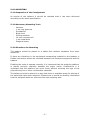
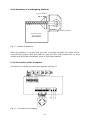
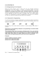
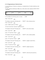
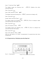
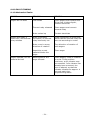
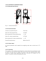
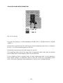
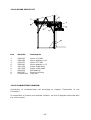
REV. 1 / 07.08.06
SMH/jj
70135GB
INSTRUCTION MANUAL
SACK WEIGHING SCALE S100
1.0.0 CONTENTS
1.0.0 CONTENTS ...................................................................................... 2
2.0.0 FIGURES ......................................................................................... 3
3.0.0 WARNING ....................................................................................... 3
4.0.0 FUNCTIONAL DESCRIPTION ........................................................... 4
5.0.0 MOUNTING ..................................................................................... 5
5.1.0 Inspection of the Consignment......................................................... 5
5.2.0 Necessary Mounting Tools ............................................................... 5
5.3.0 Directions for Mounting ................................................................... 5
5.4.0 Assembling the Bin......................................................................... 6
5.5.0 Mounting of the Augers ................................................................... 7
5.6.0 Mounting of the Weighing Platform ................................................... 8
5.7.0 Connection of the Computer ............................................................ 8
6.0.0 STARTING UP ................................................................................. 9
6.1.0 Programming of the Computer ......................................................... 9
6.1.1 Password for Programming ........................................................... 9
6.1.2 Programming of Set Up Values .................................................... 10
6.1.3 Programming of Filter Values (Suppression of Signal) ..................... 11
6.1.4 Calibration of the Scale .............................................................. 12
6.1.5 Programming of Proportioning Parameters .................................... 13
6.1.6 Programming of Weighing Quantity Required................................. 15
6.2.0 Alarm Texts................................................................................. 17
6.3.0 Starting up.................................................................................. 18
7.0.0 USER’S MANUAL ........................................................................... 19
7.1.0 Field of Application ....................................................................... 19
7.2.0 Operation ................................................................................... 19
8.0.0 MAINTENANCE.............................................................................. 20
8.1.0 Mechanical .................................................................................. 20
8.2.0 Cleaning ..................................................................................... 20
9.0.0 FAULT FINDING ............................................................................ 21
9.1.0 Mechanical Faults......................................................................... 21
9.2.0 Faults in Weighing........................................................................ 22
10.0.0 DISMANTLING THE WEIGHING SCALE ........................................ 23
11.0.0 TECHNICAL SPECIFICATIONS ..................................................... 24
11.1.0 Dimensional Sketch .................................................................... 24
11.2.0 Technical Data ........................................................................... 24
11.2.1 Noise Level ............................................................................. 24
11.2.2 Capacity................................................................................. 24
12.0.0 EX-ZONE SPECIFICATION ........................................................... 25
13.0.0 SPARE PARTS LIST ..................................................................... 26
14.0.0 CONNECTING DIAGRAM.............................................................. 26
15.0.0 CE/ATEX-DECLARATION OF CONFORMITY.................................. 27
-2-
2.0.0 FIGURES
Fig.
Fig.
Fig.
Fig.
Fig.
Fig.
Fig.
Fig.
Fig.
Fig.
1.
2.
3.
4.
5.
6.
7.
8.
9.
10.
Weighing scale............................................................................ 4
Mounting the proportioning bin ..................................................... 6
Mounting the legs........................................................................ 6
Mounting of the augers ................................................................ 7
Placing of platform ...................................................................... 8
Connection of computer ............................................................... 8
Password for programming ........................................................... 9
Control panel ............................................................................ 15
Dimensional sketch ................................................................... 24
Ex-zones.................................................................................. 25
3.0.0 WARNING
At any form of service of the weighing scale it should be ensured that the scale
cannot be started during service. This is done by the operator switching off the
power to the main switch and locking it with a key that is kept by the operator as
long as the service takes place. Alternatively the operator should remove the
fuses until service has been finalized.
El-installations MUST be carried out by an authorized
DS/EN60079-14 and DS/EN/60204-1 should be observed.
electrician,
and
All regulations according to Atex zone 21 should be observed.
All local standards should be observed.
The bin of the scale may contain an atmosphere with danger of explosion in the
form of a cloud of dust, for which reason equipment and components placed in
the bin should be ex-marked for use in zone 21 according the harmonized
standards DS/EN 50014, DS/EN 50281-1-1 and DS/EN 5050281-1-2.
In order to observe the harmonized standards regarding dust explosions DS/EN
1127-1 and DS/EN 13463-1 the cover of the proportioning bin should always be
mounted.
The scale should not be used for weighing of other products than those
mentioned in chapter 7.1 without previous consultation with the producer.
-3-
4.0.0 FUNCTIONAL DESCRIPTION
Fig. 1. Weighing scale
The weighing scale consists of a proportioning bin, pos. 1, a coarse proportioning
auger, pos. 2, a fine proportioning auger, pos. 3, a sack holder, pos. 4, and a
platform mounted on load cells, pos. 5, as well as a control box with weighing
computer.
Material is added to the proportioning bin, pos. 1.
A sack is placed in the sack holder, pos. 4.
The proportioning is started by means of a foot pedal starting both proportioning
augers, pos. 2 and 3. Weighing takes place in 2 steps. In step 1 a coarse
proportioning is carried out where both augers operate until the value for coarse
proportioning programmed is achieved. Then the fine proportioning auger
continues alone until the weight required is achieved.
-4-
5.0.0 MOUNTING
5.1.0 Inspection of the Consignment
At receipt of the balance it should be checked that it has been delivered
according to the detail specification.
5.2.0 Necessary Mounting Tools
-
Hammer
1 set ring spanners
Screwdriver
Block level
Drilling machine
10 mm concrete drill
1 set metal drills
Diagonal cutter
5.3.0 Directions for Mounting
The balance should be placed on a stable floor without vibrations from other
machines.
If there are vibrations in the equipment transporting material to the balance, a
flexible connection should be mounted between the transport equipment and the
balance.
Enabling the scale to operate correctly it is important that the weighing platform
is placed correctly vertically beneath the auger outlet. Furthermore it is
important that the platform can move freely without touching the legs of the
proportioning bin or other construction materials.
The balance should be placed in a way that there is available space for placing of
the sacks that have been weighed. Furthermore is should be carefully considered
how the weighed sacks are removed from the weighing area.
-5-
5.4.0 Assembling the Bin
When mounting the scale start with assembling the proportioning bin. Bolt the
bin together as shown on fig. 2.
Fig. 2. Mounting the proportioning bin
Then bolt the legs onto the bin as shown on fig. 3.
Fig. 3. Mounting the legs
-6-
5.5.0 Mounting of the Augers
The bin with legs can be set up, and the proportioning augers mounted.
Fig. 4. Mounting of the augers
The augers are delivered preassembled in troughs as units, pos. 2, ready for
bolting onto the flanges of the bin, pos. 1.
A tube of silicone sealant is included with the scale to be used for tightening of
possible checks and cracks of the bin.
-7-
5.6.0 Mounting of the Weighing Platform
Foot for platform
Weighing platform
Proportioning bin
Fig. 5. Placing of platform
Place the platform in a way that the inlet is vertical beneath the outlet of the
proportioning augers. Bolt the platform onto the floor and connect the in- and
outlets with a flexible connection piece in filter bag material.
5.7.0 Connection of the Computer
Connection of cables and load cells appears from fig. 6.
Fig. 6. Connection of computer
-8-
6.0.0 STARTING UP
6.1.0 Programming of the Computer
Before the sack weighing scale is taken into use, the computer should be
programmed. From the factory a number of standard values has been
programmed, but as the products to be weighed are different, it may be
necessary to re-program some of the values. The values stated in the below text
should be considered as examples of values that can be used for a large number
of the materials for which the scale is normally used. The values should,
however, be considered as a guide, and depending on products to be weighed,
you can try to alter the values and thus optimize the weighing.
6.1.1 Password for Programming
To avoid that data are changed inadvertently or by persons without permission
to do so, the computer should unlocked by means of the following code to be
entered in sequence:
Programming of the code should be carried in correct sequence and within 7
seconds.
Important: In the following example on programming are stated values
without decimal point.
The computer allows you to program a decimal point. If e.g. you want to
read kg instead of g you insert a decimal point 3 decimal points from the
right under point Ind 6. In cases where you insert a decimal point,
values with corresponding decimal points should be programmed
Example:
At Ind 1 29999 is altered to 29.999
At Ind 2 12 is altered to 0,.012
At Ind 3 12 is altered to 0,.012
1
4
5
Fig. 7. Password for programming
-9-
23
6.1.2 Programming of Set Up Values
In the following is shown an example on programming of values matching most
products.
To have access to altering of data, key in the code in the sequence stated within
7 seconds.
In the display the following text is shown:
- - Ind
Enter “Arrow left”
The display shows the following text:
- - Ind 1
(Max. display value)
Enter “Arrow left”
Press ”29999” and then ”Enter”
The new value has now been registered, and
The display shows the following text:
- - Ind 2
(No motion band)
- - Ind 3
(Zero tracking band)
- - Ind 4
(Digital overall filter)
- - Ind 5
(Digital step size)
- - Ind 6
(Decimal point position)
Enter ”Arrow left”
Press ”12” and then ”Enter”
The display shows the following text:
Enter ”Arrow left”
Press ”12” and then ”Enter”
The display shows the following text:
Enter ”Arrow left”
Press ”5” and then ”Enter”
The display shows the following text:
Enter ”Arrow left”
Press ”1” and then ”Enter”
The display shows the following text:
Enter ”Arrow left”
- 10 -
Now place the decimal point according to wish. If you insert a decimal point, the
previously programmed values are automatically amended.
Then press ”Enter”
The display shows the following text:
- - Ind 7
(Display refreshment speed)
- - Ind 8
(Industrial Certifed)
- - Ind 9
(Sampling rate)
Press ”3” and then ”Enter”
The display shows the following text:
Enter ”Arrow left”
Press ”3” and then ”Enter”
The display shows the following text:
Enter ”Arrow left”
Press ”7” and then ”Enter”
The display shows the following text:
- - Ind A
(Stabilization time 1/10 sec.)
Enter ”Arrow left”
Press ”5” and then ”Enter”
After the last keying in of ”Enter” all values have been registered in the
computer.
6.1.3 Programming of Filter Values (Suppression of Signal)
In the following is shown an example of programming of values matching most
products.
To get access to the programming, start with entering the password.
The display shows the following text:
- - Ind
Enter “Arrow down”
The display shows the following text:
- - FIL
(Display Filter Settings)
Enter ”Arrow left”
The display shows the following text:
- - FIL 1
- 11 -
(Display Filter Band)
Enter ”Arrow left”
Press ”4” and then ”Enter”
The display shows the following text:
- - FIL 2
(Display Filter Factor)
- - FIL 3
(Zero Suppression)
Enter ”Arrow left”
Press ”1” and then ”Enter”
The display shows the following text:
Enter ”Arrow left”
Press ”8” and then ”Enter”
After the last keying in of ”Enter” all filter values have been registered in the
computer.
6.1.4 Calibration of the Scale
Enter the password.
Enter ”Arrow down”
The display shows the following text:
Enter “Arrow down”
-- Ind
until
The display shows the following text:
-- CAL
(Calibration)
Enter “Arrow left”
The display shows the following text:
Enter “Arrow down”
--CAL 1
(Calibration the Instrument)
--CAL 3
(Check and or Delete Calibration
until
The display shows the following text:
Points)
Previously encoded calibration values are erased by pressing “Arrow left” for min.
3 seconds
(min. 3 seconds = erase value)
To ensure that all calibration values are erased, press “Arrow left” again for min.
3 seconds
(min. 3 seconds = erase value)
- 12 -
If there is still a calibration value, once again press the “Arrow left” for min. 3
seconds.
When all values have been erased, one of the following display texts are shown
on the display:
0
or
--CAL 3
or
Err 20
Press ”Enter”
twice
The display shows the following text:
--CAL 3
(Calibrating the Instrument)
Go to
--CAL 1
(Calibrating the Instrument)
Enter ”Arrow left”
The display shows the following text:
- CP 1 -
(Calibrating the zero point)
Enter “Arrow left”
The scale should be empty – then press “0”
and then ”Enter”
The display shows the following text:
- CP 2 -
(Calibration point 2)
Enter ”Arrow left”
Load the scale with a known weight and encode this weight.
Then press ”Enter”
The scale has now been calibrated. Press “Enter” until you reach the main menu.
6.1.5 Programming of Proportioning Parameters
In the following is shown an example of programming of values matching most
products.
To get access to altering data enter the password
Enter ”Arrow down”
- 13 -
The display shows the following text:
- - Ind
Enter “Arrow down”
The display shows the following text:
-- FIL
Enter “Arrow down”
The display shows the following text: - - CAL (Calibration - if the scale should
calibrated we refer to the manual of the computer)
Enter ”Arrow down”
The display shows the following text:
should not be used)
-- dAC
(Programming of analog signals,
Enter ”Arrow down”
The display shows the following text:
-- dAr
(Display configuration)
Enter “Arrow down”
The display shows the following text:
--CFG 1
(Stabilization time)
--CFG 2
(Positive or negative weighing)
--CFG 3
(Nett or gross weighing)
Enter “Arrow left”
Press ”0” and then ”Enter”
The display shows the following text:
Enter “Arrow left”
Press ”1” and then ”Enter”
The display shows the following text:
Enter “Arrow left”
Press ”1” and then ”Enter”
The display shows the following text: --CFG
kinetic energy after coarse proportioning)
4
(Value for compensation of
Enter “Arrow left”
Press ”225” and then ”Enter”
The display shows the following text:
--CFG 5
Enter ”Arrow left”
- 14 -
(Correction factor)
Press ”1” and then ”Enter”
The display shows the following text:
proportioning mS)
--CFG 6
(Waiting time after
Enter ”Arrow left”
Press ”4000” and then ”Enter”
The display shows the following text:
--CFG 7
(view time for display mS)
Enter ”Arrow left”
Encode ”4000” and then ”Enter”
The display shows the following text:
proportioning after start signal mS)
--CFG 8
(Time for delayed coarse
Enter ”Arrow left”
Press ”50” and then ”Enter”
The display shows the following text:
proportioning after start signal)
--CFG 9
(Time for delayed fine
Enter ”Arrow left”
Press ”200” and then ”Enter”
After the last keying in of ”Enter” all parameters for proportioning have been
programmed.
6.1.6 Programming of Weighing Quantity Required
Fig. 8. Control panel
Press ”M” for more than 3 seconds
- 15 -
When programming the quantity you want to weigh, press the ”M”-key briefly,
and the display starts flashing. Then the quantity you want to weigh is
programmed. If you e.g. want 50 kg, encode 50000, and end up with “Enter” (if
you have chosen decimals in ”decimal point position ind 6”, key in 50).
To have an accurate weighing, the quantity when the fine proportioning auger is
operating be programmed. If you e.g. require 47 kg with both augers and 3 kg
with the fine proportioning auger proportioning alone, the 3 kg should be
programmed. This point is called the “switch over” point, and it takes place in
continuation of the programming of the required weighed quantity. When the
required total quantity has been programmed and finalized by enter, press the
“M”-key again for min. 3 seconds. The display shows “dS1”. Press “arrow left”
and then 3000 (or 3 if you have chosen decimals, and the indicated value is in
kg). End up with 2 x enter.
Then carry out 5 test weighings that are controlled on an accurate scale, and
calculate the average weight. This weight will normally deviate slightly from the
required quantity, as a certain quantity of material will be floating in the air when
the fine proportioning auger is stopped by the computer. To compensate for this
quantity, the correction factor, by which the programmed quantity should be
adjusted, should be calculated. If the average of these test weighings is lower
than the value required the required weight should be adjusted upwards
correspondingly.
Example:
50000 g have been programmed being the weight required.
In average 49750 g are weighed.
I.e. 250 g per weighing is missing.
Therefore program the corrected required weight being 50250 g.
If the quantity weighed is higher than the required one, the required weight
should be adjusted downwards by the quantity that has been weighed too much.
During the test weighing you should also check that the ”switch over point” has
been programmed in a way that the fine proportioning auger operates alone
during the last time of proportioning. If the “switch over point” is programmed so
that the time becomes too long, the weighing time will be longer than necessary.
- 16 -
6.2.0 Alarm Texts
Input value too large
Dead load instable
Overflow “CAL4”. The shift is too large (it was larger than 32,000 internal parts)
ADC underflow
ADC overflow
No calibration points available
Resolution too low for calibration segment 1.
Resolution too low for the calibration segments indicated by the last digit of this
error message
Resolution too low for calibration segment 4
No calibration points left or CAL. point is not existing
After changing the step size. Resolution too low for calibration segment 1
After changing the step size and recalculation the resolution is too low for the
calibration segments indicated by the last digit of this error message
After changing the step size. Resolution too low for calibration segment 4
No proper calibration available
Underflow
Overflow
Display overflow
Press the “M” button to proceed
- 17 -
6.3.0 Starting up
Before the sack weighing scale is taken into use, check:
- If there are foreign bodies in the auger troughs and the machines with
connection to the scale.
- If the bolts have been tightened.
The power is turned on:
- Do the augers run in correct direction?
- 18 -
7.0.0 USER’S MANUAL
7.1.0 Field of Application
The sack weighing scale is used for weighing of dry materials as grain, meal and
pelleted materials. If you want to use the scale for other materials / fields,
please contact the manufacturer before doing so, as otherwise the guarantee will
become void.
7.2.0 Operation
During weighing you should try to keep so much material in the proportioning bin
that the auger threads are covered. If you fill material into an empty silo during
weighing, it may occur that material passes through the auger threads forming a
cloud of dust, just as the weighing may be inaccurate.
At weighing out an empty sack is placed on the weighing platform, and a foot
pedal is activated, giving start signal to the 2 proportioning augers. To achieve a
good weighing accuracy, the large auger stops before the weight required has
been reached, and the fine proportioning auger continues until the correct
quantity has been reached.
When weighing place an empty sack on the weighing platform and activate the
foot pedal giving start signal to the two proportioning augers. To achieve a good
weighing accuracy, stop the large auger before the weight required is reached,
and the fine proportioning auger continues until the correct quantity is reached.
It is important that the sack and weighing platform is not touched during
weighing.
As the material falls from the augers into the sack, the inertia of the falling
material will affect the load cell so that the material weighs less when it is in the
sack. It is therefore quite normal that the value that is programmed as required
quantity should be programmed to be higher than the quantity required.
Therefore carry out some test weighings to find the value to be corrected.
Furthermore see the chapter “Programming of the Computer”, especially chapter
“Programming of Proportioning Parameters”.
- 19 -
8.0.0 MAINTENANCE
8.1.0 Mechanical
The weighing scale is constructed in a way that it requires minimum
maintenance. All bearings are lifetime-greased.
After 1 month of operation:
- Check bolts and nuts and retighten if necessary.
Then check:
Each month:
-
Check bearings.
Clean motors and electrical controllers for dust and moisture.
Remove possible accumulations in trough as well as in- and outlets.
Check wear of threads, pipes and clamps.
8.2.0 Cleaning
All cleaning should take place in a way that no dust clouds with danger of
explosion are generated. Pressure air should therefore not be used. Instead use
broom and vacuum cleaner.
To ensure necessary cooling and thereby decrease the risk of fire, the motor and
gear should be kept free of dust.
If the auger is not used for a long time, check trough as well as in- and outlets
for accumulations and impurities.
- 20 -
9.0.0 FAULT FINDING
9.1.0 Mechanical Faults
FAULT
REASON
Augers do not start
Fuse blown
Clean augers and replace fuse.
If the fuse is blown again,
contact electrician
Thermal relay released
Clean augers and connect
thermal relay
Motor seized up
Contact electrician
Augers stop after a
short time, and thermal
relay releases
Augers operate, but no
material arrives
REMEDY
Motor incorrectly
connected, or thermal
relay incorrectly set
Check connection of motor and
check that the thermal relay has
been set according to motor
Motor runs in wrong
direction of rotation
Turn direction of rotation of
both augers
Impurities or wet
material blocks the
auger
Clean auger
Blocking above the
auger threads
Clean augers, check if material
is moist. If the problem
continues, a silo vibrator may
be mounted. I silo vibrator has
already been mounted, the
time is altered, so that the
vibrator vibrates for approx. 4
seconds each time
proportioning starts
- 21 -
9.2.0 Faults in Weighing
FAULT
REASON
REMEDY
The quantity weighed has You have not corrected for Correct according to
the same deviation each
the material moving when chapter “Programming of
time
it hits the sack
Proportioning Parameters”
Too large deviations in
weighed quantity
The weighing platform
cannot move freely
Clean around the
weighing platform and
check that it does not hit
foreign bodies
Manually correct for
contents of the sack
Sack or weighing platform Place sack accurately,
is touched during
possibly move weighing
weighing
platform
The balance is unstable
Coarse proportioning
auger operates too long
Program the “switch over
point” to a longer time,
see chapter
“Programming of
Proportioning Parameters”
Programming values do
not fit the required
parameters for weighing
Program a lower value for
“Ind2” and for “IndA”, see
chapter “Programming of
the Computer”
Load cell defective
Replace load cell
- 22 -
10.0.0 DISMANTLING THE WEIGHING SCALE
Dismantling of the weighing scale takes place in reverse order as mounting, and
the same tools are to be used, see chapter “Necessary Mounting Tools”.
We cannot recommend use of angle grinder or cutting torch – this should only
take place when all safety rules are obtained. Beyond normal safety rules, the
weighing scale should be cleaned for inflammable material and should be outside
environments with fire or explosion hazard.
Disposal of the weighing scale can take place in containers for scrap iron. The
control panel should, however, be disposed of in containers for electronic parts.
- 23 -
11.0.0 TECHNICAL SPECIFICATIONS
11.1.0 Dimensional Sketch
Fig. 9. Dimensional sketch
11.2.0 Technical Data
Volume of proportioning bin
700 litres
Motor for fine proportioning
0.09 kW
Worm gearing for fine proportioning
i = 20
Motor for coarse proportioning
0.37 kW
Worm gearing for coarse proportioning
i = 15
Proportioning accuracy
Better than 1%
11.2.1 Noise Level
At normal production with material the weighing scale has a noise level of 72
dBA.
11.2.2 Capacity
The capacity of the weighing scale depends on the material to be weighed as well
as sack size and how the sacks are moved from the weighing scale (sack
conveyor or sack trolley, operation staff etc.). Normally the capacity will be
approx. 3 tons/hour when 50 kg sacks are used.
- 24 -
12.0.0 EX-ZONE SPECIFICATION
Fig. 10. Ex-zones
Ex-zones according to unified standards DS/EN 1127-1, DS/EN 50281-3, DS/EN
13463-1.
Around the proportioning bin and augers of the weighing scale and in a distance
of min. 1 m to the extreme point is zone 22.
Inside the proportioning bin with augers is zone 21.
The weighing scale should be kept free of deposited dust that may be swirled
around and form an atmosphere with risk of explosion.
If the weighing scale is placed close to other equipment with a zone stated to
have larger danger of explosion and so that the zones are overlapping each
other, the most important zone statement is valid in the overlapped area.
- 25 -
13.0.0 SPARE PARTS LIST
Pos
Item No.
Description
1
2
3
4
5
6
7
8
9
2340137
2392056
2391037
2391040
1501124
1501125
6404025
6407087
DT2800/200
Motor 0.09 kW
Worm gearing i=20
Motor 0.37 kW
Worm gearing i=15
Auger shaft large
Auger shaft small
Ball bearing
Bearing housing
Load cell
14.0.0 CONNECTING DIAGRAM
Connection of computer/load cell according to chapter ”Connection of the
Computer”.
At connection of motors and possible vibrator, see the el-diagram delivered with
the control panel.
- 26 -
15.0.0 CE/ATEX-DECLARATION OF CONFORMITY
The signer
SKIOLD A/S
Kjeldgaardsvej, 9300 Sæby, Danmark, tel. No. +45 99 89 88 87
hereby declares that:
Description
Type
Weighing scale
S100
is constructed for erection in ATEX-zone 22 and in conformity with the
following directives:
Directive
Standard
CE/ATEX directives with updates
DS/EN
DS/EN
DS/EN
DS/EN
DS/EN
DS/EN
DS/EN
DS/EN
Sæby, Denmark, 31.08.2006
Issue place and date
292-1
292-2
294-1
1127-1
13463-1
50281-1-1
50281-1-2
60204-1
_______________________
Samuel Waldorph
General Manager
- 27 -