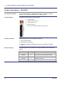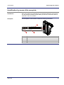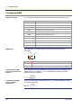
1
JX3-DO16 Digital Output Module 60874420 Introduction Item # 60874420 Revision 2.35.4 September 2013 / Printed in Germany This document has been compiled by Jetter AG with due diligence, and based on the known state of the art. In the case of modifications, further developments or enhancements to products shipped in the past, a revised document will be supplied only if required by law, or deemed appropriate by Jetter AG. Jetter AG shall not be liable for errors in form or content, or for missing updates, as well as for damages or disadvantages resulting from such failure. The logos, brand names, and product names mentioned in this document are trade marks or registered trade marks of Jetter AG, of associated companies or other title owners and must not be used without consent of the respective title owner. 2 Jetter AG JX3-DO16 Address Introduction How to contact us: Jetter AG Graeterstrasse 2 71642 Ludwigsburg Germany Assignment to product Phone - Switchboard: +49 7141 2550-0 Phone - Sales: +49 7141 2550-433 Phone - Technical Hotline: +49 7141 2550-444 Fax - Sales: +49 7141 2550-484 E-mail - Sales: [email protected] E-mail - Technical Hotline: [email protected] This Application Note is an integral part of JX3-DO16: Type: Serial #: Year of manufacture: Order #: To be entered by the customer: Inventory #: Place of operation: Jetter AG 3 Introduction Significance of this Application Note This document is an integral part of the JX3-DO16: Keep this document in a way that it is always at hand until the JX3-DO16 will be disposed of. Pass this document on, if the JX3-DO16 is sold or loaned/leased out. In any case you encounter difficulties to clearly understand this document, please contact Jetter AG. Jetter AG would appreciate any suggestions and contributions on your part and would ask you to contact Jetter AG at the following e-mail address: [email protected]. This will help the documentation department produce documents that are more user-friendly, as well as address your wishes and requirements. This document contains important information on the following topics: Transport Mounting Installation Programming Operation Maintenance Repair Therefore, the user must carefully read, understand and observe this document and especially the safety instructions. In the case of missing or inadequate knowledge of this document, Jetter AG shall be exempted from any liability. Therefore, the operating company is recommended to obtain the persons' confirmation in writing that they have read and understood this document. 4 Jetter AG JX3-DO16 Contents Table of Contents 1 Safety instructions 9 Basic Safety Instructions.............................................................................................................. 10 Instructions on EMI ...................................................................................................................... 12 2 Product description and equipment configuration 13 Product description – JX3-DO16 ................................................................................................. 14 JX3 modules: List of documentation ............................................................................................ 15 Parts and interfaces of the JX3-DO16 module ............................................................................ 17 Internal block diagram .................................................................................................................. 18 Minimum requirements ................................................................................................................ 19 Accessories for the JX3 system ................................................................................................... 20 Physical dimensions .................................................................................................................... 21 3 Identifying the module 23 Module revisions .......................................................................................................................... 24 Electronic Data Sheet EDS with JC-3xx ...................................................................................... 26 Electronic Data Sheet EDS - JC-24x ........................................................................................... 28 Electronic Data Sheet EDS - JC-647 + JX6-SB(-I) ...................................................................... 30 Example: Reading out an EDS - JC-3xx...................................................................................... 32 Example: Reading out an EDS - JC-24x ..................................................................................... 34 Identifying the module .................................................................................................................. 36 Identification by means of the nameplate .................................................................................... 37 4 Mounting and installation 4.1 4.2 5 39 Interfaces .................................................................................................................................... 40 Assignment of terminal X31 ......................................................................................................... 41 Assignment of terminal X32 ......................................................................................................... 43 Internal block diagram .................................................................................................................. 45 BLZF connector specification for terminals X21/X32 ................................................................... 46 Connecting digital actuators......................................................................................................... 47 BLIO connector specification for terminals X31/X32 ................................................................... 49 BLZF connector specification for terminals X31/X32 ................................................................... 50 Limiting the total output current.................................................................................................... 51 LEDs on the JX3-DO16 module................................................................................................... 52 Installing, replacing and removing the module ...................................................................... 54 Installing the JX3 peripheral module on a DIN rail....................................................................... 55 Replacing the JX3 peripheral module .......................................................................................... 56 Removing the JX3 peripheral module from the DIN rail .............................................................. 58 Initial commissioning 61 Preparatory work for initial commissioning .................................................................................. 62 Initial commissioning - JX3-DO16 connected to a JC-3xx ........................................................... 63 Initial commissioning - JX3-DO16 connected to a JC-24x .......................................................... 64 Jetter AG 5 Contents 6 Programming 6.1 6.2 6.3 6.4 6.5 6.6 7 65 Abbreviations, module register properties and formats .............................................................. 66 Register and I/O Numbering for JX3 Modules ........................................................................ 67 Registers and module registers .................................................................................................. 68 I/O module numbers on the JX2 system bus .............................................................................. 69 Register and I/O Numbers with JC-24x and JM-D203-JC-24x ................................................... 70 Register and I/O Numbers with JC-3xx ....................................................................................... 71 Register and I/O Numbers for JC-647 with JX6-SB(-I) ............................................................... 72 Register and I/O Numbers for JC-800 with JX6-SB(-I) ............................................................... 73 Register and I/O Numbers for JC-9xx with JX6-SB(-I)................................................................ 74 Register access to JX3 modules on the JX2 system bus ..................................................... 75 Direct register access to JX3 modules on the JX2 system bus .................................................. 76 Example - Direct register access ................................................................................................ 77 Indirect register access to JX3 modules on the JX2 system bus ................................................ 78 Example - Indirect register access .............................................................................................. 80 Module registers for indirect register access............................................................................... 81 Programming by JetSym module headers ............................................................................. 82 Module headers for JC-24x or JX6-SB(-I) and JetSym ST ......................................................... 83 Module header for JC-3xx and JetSym STX ............................................................................... 84 Switching of outputs ................................................................................................................. 85 Writing all output values .............................................................................................................. 86 Example: Switching digital outputs - JX3-DO16 connected to a JC-3xx..................................... 87 Example: Switching digital outputs - JX3-DO16 connected to a JC-24x .................................... 89 Example: Switching digital outputs - JX3-DO16 connected to a JC-647 equipped with JX6-SB(-I) ........... 91 Error states of digital outputs .................................................................................................. 93 Configuring error states ............................................................................................................... 94 Description of registers - Error states .......................................................................................... 95 Example: Configuring error states for a JX3-DO16 connected to a JC-3xx ............................... 97 Example: Configuring error states for a JC-24x .......................................................................... 99 Pulse-width modulation (PWM).............................................................................................. 101 Functionality of pulse width modulation PWM........................................................................... 102 Configuring PWM ...................................................................................................................... 104 Changing PWM parameters while PWM is active ..................................................................... 107 Register description - Pulse width modulation PWM ................................................................ 109 Example: Enabling the PWM function with a JX3-DO16 connected to a JC-3xx ...................... 113 Example: Enabling the PWM Function - JC-24x ........................................................................ 115 Detecting faults 117 LEDs on the JX3-DO16 module ................................................................................................. 118 Diagnostics of error messages via module registers ................................................................ 120 Short circuit/overload at the output driver ................................................................................. 121 Description of registers: Evaluation of errors ............................................................................ 122 8 Quick reference - JX3-DO16 Appendix A: 6 123 125 Technical Data ......................................................................................................................... 126 Technical specifications ............................................................................................................. 127 Physical dimensions .................................................................................................................. 128 Operating parameters - Environment and mechanics .............................................................. 129 Operating parameters - Enclosure ............................................................................................ 130 Jetter AG JX3-DO16 B: Jetter AG Contents DC power supply inputs and outputs ......................................................................................... 131 Shielded data and I/O lines ........................................................................................................ 132 Index .......................................................................................................................................... 133 7 JX3-DO16 1 Safety instructions Safety instructions Introduction This chapter informs the user of general safety instructions. It also warns of residual dangers, if applicable. This chapter also contains information on EMC. Contents Topic Page Basic Safety Instructions .............................................................................. 10 Instructions on EMI ....................................................................................... 12 Jetter AG 9 1 Safety instructions Basic Safety Instructions Introduction This device complies with the valid safety regulations and standards. Jetter AG attaches great importance to the safety of the users. Of course, the user should adhere to the following regulations: Relevant accident prevention regulations; Accepted safety rules; EC guidelines and other country-specific regulations Intended conditions of use Usage according to the intended conditions of use implies operation in accordance with this Application Note. The JX3-DO16 has been designed as a peripheral module for use in machines and is intended for connection to an already existing controller. The JX3-DO16 is a peripheral module. Only operate the JX3-DO16 module within the limits and conditions set forth in the technical specifications. Because of its low operating voltage, the JX3-DO16 module is classified as SELV (Safety Extra Low Voltage). The JX3-DO16 module is therefore not subject to the EU Low Voltage Directive. Usage other than intended This device must not be used in technical systems which to a high degree have to be fail-safe, e. g. ropeways and aeroplanes. The JX3-DO16 is no safety-related part as per Machinery Directive 2006/42/EC. This device is not qualified for safety-relevant applications and must, therefore, NOT be used to protect persons. If you intend to operate the device at ambient conditions not being in conformity with the permitted operating conditions, please contact Jetter AG beforehand. Personnel qualification Depending on the life cycle of the product, the persons involved must possess different qualifications. In order to grant safety in handling the device at each phase of the product life cycle, the following requirements must be met. Modifications and alterations to the module 10 Product life cycle Minimum qualification Transport/storage: Trained and instructed personnel with knowledge in handling electrostatic sensitive components. Mounting/installation: Specialized personnel with training in electrical engineering, such as industrial electronics technician. Commissioning/programmi ng: Trained and instructed experts with profound knowledge of, and experience with, electrical/drive engineering, such as electronics engineer for automation technology. Operation: Trained, instructed and assigned personnel with knowledge in operating electronic devices. Decommissioning: Specialized personnel with training in electrical engineering, such as industrial electronics technician. For safety reasons, no modifications and changes to the device and its functions are permitted. Jetter AG JX3-DO16 Safety instructions Any modifications to the device not expressly authorized by Jetter AG will result in a loss of any liability claims to Jetter AG. The original parts are specifically designed for the device. Parts and equipment from other manufacturers are not tested, and therefore not released by Jetter AG. The installation of such parts may impair the safety and the proper functioning of the device. Any liability on the part of Jetter AG for any damages resulting from the use of non-original parts and equipment is excluded. Transporting JX3 modules The JX3 module contains electrostatic sensitive components which can be damaged if not handled properly. To prevent damages to JX3 modules, the JX3 backplane bus has to be attached during transport. This is particularly true for transport via mail. To prevent the JX3 module from being damaged, ship it only in its original packaging and in packaging protecting against electrostatic discharge. In case of damaged packaging inspect the device for any visible damage. Inform your freight forwarder and Jetter AG. Storing When storing the JX3-DO16 observe the environmental conditions given in the technical specification. Repair and maintenance The operator is not allowed to repair the device. The device does not contain any parts that could be repaired by the operator. If the device needs repairing, please send it to Jetter AG. Replacing modules During exchange of JX3 modules, class of protection IP20 is not ensured. Do not touch any electronic components once a JX3 module housing has been removed from the JX3 backplane module. If you touch the EMC clip, you may damage this clip. A damaged clip may result in lower noise immunity. Disposal When disposing of the device, the local environmental regulations must be complied with. Jetter AG 11 1 Safety instructions Instructions on EMI Noise immunity of a system The noise immunity of a system depends on the weakest component of the system. For this reason, correct wiring and shielding of cables is of paramount importance. Measures Measures for increasing EMI in electric plants: The module JX3-DO16 must be attached to a DIN rail acc. to EN 50022-35 x 7.5. Follow the instructions given in Application Note 016 "EMC-Compatible Installation of the Electric Cabinet" published by Jetter AG. The following instructions are excerpts from Application Note 016: Maintain physical separation between signal and power lines. Jetter AG Downloading Application Note 016 12 recommend spacings greater than 20 cm. Cables and lines should cross each other at an angle of 90°. The following line cables must be shielded: Analog lines, data lines, motor cables coming from inverter drives (servo output stage, frequency converter), lines between components and interference suppressor filter, if the suppressor filter has not been placed at the component directly. Shield cables at both ends. Unshielded wire ends of shielded cables should be as short as possible. The entire shield must, in its entire perimeter, be drawn behind the isolation, and then be clamped under an earthed strain relief with the greatest possible surface area. You can download Application Note 016 from the Jetter AG homepage at www.jetter.de http://www.jetter.de. In order to download Application Note 016 "EMC-Compatible Installation of Electric Cabinets" browse the following path: Industrial Automation - Support - Downloads - 07_application_notes". Jetter AG JX3-DO16 2 Product description and equipment configuration Product description and equipment configuration Introduction This chapter covers the design of the device, as well as how the order reference is made up including all options. Contents Topic Page Product description – JX3-DO16 .................................................................. 14 JX3 modules: List of documentation............................................................. 15 Parts and interfaces of the JX3-DO16 module ............................................. 17 Internal block diagram .................................................................................. 18 Minimum requirements ................................................................................. 19 Accessories for the JX3 system ................................................................... 20 Physical dimensions ..................................................................................... 21 Jetter AG 13 2 Product description and equipment configuration Product description – JX3-DO16 The JX3-DO16 module The JX3-DO16 module is a peripheral module for connection of digital actuators. This module is equipped with 16 digital outputs. Product features The features of this product are listed below: Additional features 16 digital outputs Output voltage: DC +24 V Output current: 0.5 A Short-circuit proof Color of LED membrane: traffic red (RAL 3020) Additional features of the JX3-DO16 module are: Short-circuit detection Output of error conditions Pulse width modulation (PWM) which can be configured for 8 digital outputs Scope of delivery 14 The following items are included in the scope of delivery of the JX3-DO16 module: Jetter item no. Quantity Description 10000595 1 JX3-DO16 60869252 2 10-pin connector, spring-cage technology 60870411 10 Terminal labels 60872692 1 Installation instruction 60870410 1 Keying pins Jetter AG JX3-DO16 Product description and equipment configuration JX3 modules: List of documentation Introduction Various documents and software tools will support the user when engineering, installing and programming the JX3-DO16 module. These documents and software tools can be downloaded from the Jetter AG homepage http://www.jetter.de. Engineering When performing engineering tasks, the following documents and files will support you: Data sheet on the JX3-DO16 module Product description Technical specifications Dimensional drawings User manual on the JX3-DO16 module the document at hand CAD data of the JX3-DO16 module dxf file with 2D illustrations stp file with 3D illustrations User manual on the JC-3xx control system Engineering a JX3 station on the JX2 system bus Engineering a JX3 station Product descriptions of JX3 modules The following document and software tool will support you in engineering a JX3 station on the JX2 system bus (JC-24x and JC-647): JX2-I/O system - User information System bus topology JX2 system bus specification Product descriptions of JX3-BN-CAN, JX2 and IP67 modules, as well as third-party modules System bus configurator Engineering a JX3 Station on the JX3 System Bus Excel file for designing the system bus SysBus_Configuration_xxx_e.xls (xxx: version) The following document and software tool will support you in engineering a JX3 station on the JX3 system bus (JC-3xx): System bus configurator Jetter AG Excel file for designing the system bus JX3-SysBus_Configurator_xxx_e.xls (xxx: version) 15 2 Product description and equipment configuration Installation The following document will support you in installing modules: Installation Instruction It is included in the boxed module JX3-DO16 and contains information on: Installation of the module on a DIN rail Terminal assignment Specification of conductor terminals Diagnostics via LEDs User manual on the JX3-DO16 module Programming the document at hand The following documents and software tools will support you in programming the module: User manual on the JX3-DO16 module the document at hand JX2-I/O system - User information Module numbering system Diagnostics of the modules on the JX2 system bus JetSym Programming tool User manual on the controller 16 Depending on the controller used you will need the corresponding manual Jetter AG JX3-DO16 Product description and equipment configuration Parts and interfaces of the JX3-DO16 module Parts and interfaces The illustration below shows the parts and interfaces of the JX3-DO16 module: Number Element Description 1 Upper latch Lets you remove the JX3 module enclosure from the JX3 backplane module 2 JX3 backplane module Support and connection device 3 Connector Connector for additional JX3 modules 4 JX3 module enclosure Can be removed from the JX3 backplane module 5 DIN rail latch For removing the JX3 module from the DIN rail. 6 Lower latch Lets you remove the JX3 module enclosure from the JX3 backplane module 7 Terminal X32 Terminal of digital outputs OUT 9 ... 16 8 Terminal X31 Terminal of digital outputs OUT 1 ... 8 9 LEDs Diagnostic and status LEDs Jetter AG Not visible in the illustration 17 2 Product description and equipment configuration Internal block diagram Internal block diagram This module JX3-DO16 is equipped with 16 digital outputs. X31.DC24V 22 µF FPGA X31.1 10 nF X31.8 10 nF X31.0V X32.DC24V 22 µF X32.9 10 nF X32.16 10 nF 0Ω Element 18 X32.0V Description FPGA Communication chip 10 nF Capacitance on the digital output 22 µF Capacitance on the power supply for outputs X31.DC24V Power supply of digital outputs OUT 1 ... 8 X32.DC24V Power supply of digital outputs OUT 9 ... 16 Jetter AG JX3-DO16 Product description and equipment configuration Minimum requirements Keeping the software version up-to-date You operate the JX3-DO16 module in a system consisting of various components by Jetter AG. In order to ensure proper interaction of these components the operating system used and the programming tool JetSym must have the release numbers listed below. Configurations The module JX3-DO16 can be connected to JetControl 3xx Ethernet bus node JX3-BN-ETH JX2 system bus of a JetControl 24x via CAN bus node JX3-BN-CAN JX2 system bus of a dual-axis controller JM-D203-JC24x via CAN bus node JX3-BN-CAN JX2 system bus of a JetControl JC-647 equipped with a submodule JX6-SB(-I) via CAN bus head JX3-BN-CAN JX2 system bus of a JetControl 9xx equipped with a submodule JX6-SB(-I) via CAN bus node JX3-BN-CAN To be able to use the functions described in this document, the modules, controllers and software must meet the following minimum requirements: Jetter AG BCDE A MID BCDE F 01 2 LOW 1 2 9 10 1 2 3 4 11 12 3 4 5 6 13 14 5 6 7 8 15 16 7 8 E D1 D2 0V SHLD U4+ RUN 0V SHLD X10 DC24V 0,5A 0V X51 I1+ 0V 0V SHLD U2+ X19 0V SHLD X52 I3+ 0V 0V SHLD U4+ U4+ I4+ 0V E D1 D2 I2+ 24V 0V 0V R Jetter 0V 5V ERR I3+ SHLD JX3-AO4 R X18 OUTPUT BUS OUT X15 I3+ X52 I4+ X10 0V 0V SHLD 6 Element F 01 2 INPUT 0V SHLD POWER SER SD-CARD DC24V 1,2A 0V INPUT 0V 0V X10 S33 I2+ HIGH POWER X61 SER2 A ETHERNET ETHERNET 0V SHLD X52 X15 X11 S32 0V U2+ I2+ 0V 0V JetWeb JC-243 F 01 2 E 7 8 9 0V SHLD U2+ Jetter ADRESS S31 3 4 5 BUS OUT I1+ X14 0V SHLD No. LOAD JX3-BN-CAN STOP RUN SER1 X51 I1+ X14 5 E D1 D2 3 4 56 STOP POWER R Jetter BCD E D1 D2 A R X51 3 4 56 X19 JX3-AO4 E D1 D2 JX3-BN-ETH JX3-AO4 R Jetter S11 LOAD 7 8 9 JC-340 E D1 D2 RUN 4 7 8 9 R 3 BUS IN 2 1 6 Minimum requirements DC24V 0,5A 0V I4+ 0V 0V SHLD 6 Description 6 Minimum software version (or higher) 1 JetSym Programming software V 3.00 2 JC-3xx PLC JetControl 3xx V 1.09.0.00 3 JX3-BN-ETH Ethernet bus node V 1.09.0.00 4 JC-24x PLC JetControl 240 V 3.23 JC-647 PLC JetControl 647 V 3.50 JX6-SB(-I) Submodule for the system bus V 2.17 JM-D203-JC24x Dual-axis controller with integrated controller JetControl 240 V 1.12.0.00 5 JX3-BN-CAN CAN bus node V 1.03.0.00 6 JX3-DO16 Digital output module V 2.35.0.00 19 2 Product description and equipment configuration Accessories for the JX3 system Labelling strips Keying pins Strain relief for BU_10_E_BLZF_GE_RM 3.5 End clamp for DIN rail Screwdriver 20 Ten labelling strips are included in the scope of delivery of the JX3-DO16 module. Designation DIV_DEK_5/5_MC-10_NEUT_WS Jetter item no. 60870411 Packaging unit 100 pcs. One keying pin is included in the scope of delivery of the JX3-DO16 module: Designation DIV_BL_SL_3.5_KO_OR Jetter item no. 60870410 Designation DIV_BL_3.5_ZE_8 Jetter item no. 60870963 Designation DIV_CLIPFIX_35 Jetter item no. 60863970 Type SD 0.4 x 2.5 - DIN 5264-A Designation DIV_SCHRAUBENDREHER_2,5*75 Jetter item no. 60871712 Jetter AG JX3-DO16 Product description and equipment configuration Physical dimensions Physical dimensions Minimum clearances At mounting the JX3-DO16 module, make sure to maintain a minimum clearance above and below. This ensures that there will be enough room to press the latches of the JX3 backplane module when replacing modules. Minimum clearance, above: 30 mm Minimum clearance, below: 25 mm Module width The JX3-DO16 module requires a space of 31 mm width. At connecting the JX3-DO16 module to a JX3 station, the width is increased by 25 mm. Mounting orientation The mounting orientation of the JX3-DO16 module is vertical. Jetter AG 21 JX3-DO16 3 Identifying the module Identifying the module Purpose of this chapter This chapter supports you in obtaining the following information from the JX3-DO16 module: Determining the revision of this module. Retrieving Electronic Data Sheet (EDS) information. Numerous manufacturing-relevant data are stored to EDS. Prerequisites To be able to identify the JX3-DO16 module the following prerequisites must be fulfilled: Information for hotline requests The JX3-DO16 module is connected to a JetControl PLC. The controller is connected to a PC. The programming tool JetSym is installed on the PC. The minimum requirements regarding modules, controllers and software are fulfilled. If you wish to contact the hotline of Jetter AG in case of a problem, please have the following information on the JX3-DO16 module ready: Version number in MR 9 Hardware revision Module code The module code of the JX3-DO16 is 302. Contents Topic Page Module revisions ........................................................................................... 24 Electronic Data Sheet EDS with JC-3xx ....................................................... 26 Electronic Data Sheet EDS - JC-24x ............................................................ 28 Electronic Data Sheet EDS - JC-647 + JX6-SB(-I)....................................... 30 Example: Reading out an EDS - JC-3xx ...................................................... 32 Example: Reading out an EDS - JC-24x ...................................................... 34 Identifying the module .................................................................................. 36 Identification by means of the nameplate ..................................................... 37 Jetter AG 23 3 Identifying the module Module revisions Introduction Each JX3 module features software with a unique revision number which can be read out via module registers. You will need these revision data if you have to contact the hotline of Jetter AG in case of a problem. Revision number format The revision numbers of the JX3-DO16 module are four-figure values. 1 . 2 . 3 . 4 Element Register overview Description 1 Major or main version number 2 Minor or secondary version number 3 Branch or intermediate version number 4 Build version number Revision numbers can be read out of the following module registers: Register Description MR 9 OS version MR 32 FPGA revision MR 769 Bootloader version Released version A released version can be recognized by both Branch and Build having got the value 0. Version numbers in the JetSym setup For displaying the version number in the setup pane of JetSym, select the format "IP address". 24 Jetter AG JX3-DO16 Software versions Identifying the module The sample program has been tested on the following software versions: JetSym version 4.4.3 Control system JC-24x of OS version 3.27.0.00 Module JX3-DO16 of OS version 2.35.0.00 For sample programs on the most recent software releases please turn to the JetSym online help. Revision numbers in the JetSym ST application program To display a revision number in the application program use identifier IP#. The JX3 module out of which the OS version specified in this example is read out, has got I/O-module number 3. Var JX3_Module_revision : Int At %VL 3019; End_Var; Task 0 // Checking a revision number When JX3_Module_revision = IP#1.1.0.0 Continue; // ... End_Task; Related topics Register description - Identification (see page 36) Jetter AG 25 3 Identifying the module Electronic Data Sheet EDS with JC-3xx Introduction Numerous production-relevant data are permanently stored to the EDS. EDS information can be retrieved from registers on the controller JC-3xx. Register overview The following registers let you read out EDS data: Register EDS page 0 - Contents R 100500 Interface: 1 = Peripheral modules of the JX3 station R 100501 Module number within the JX3 station R 100600 ... R 100614 EDS page 0 - Data R 100700 ... R 100710 EDS page 1 - Data Production-related data can be read from EDS page 0. Register EDS page 1 - Contents Type Description R 100600 int Revision of EDS page 0 R 100601 int Module code R 100602 ... R 100612 string Module name R 100613 int Hardware revision R 100614 int Hardware revision Production-related data can be read from EDS page 1. Register 26 Description Type Description R 100700 int Revision of EDS page 1 R 100701 ... R 100707 string Serial number R 100708 int Production date: day R 100709 int Production date: month R 100710 int Production date: year Jetter AG JX3-DO16 Reading an EDS page Identifying the module To read an EDS page of a JX3 module connected to a JC-3xx proceed as follows: Step Action 1 Select the interface by entering 1 into R 100500. 2 Select the JX3-module by entering the module number into R 100501. 3 Read out EDS data from registers R 100600 ... 100710. Related topics Example: Reading out an EDS - JC-3xx Jetter AG 27 3 Identifying the module Electronic Data Sheet EDS - JC-24x Introduction Numerous production-relevant data are permanently stored to the EDS. Special registers let you retrieve EDS information. This information is distributed among EDS page 0 and EDS page 1. Only one page at a time can be accessed via registers. Register overview The following registers let you read out EDS data: Register EDS page 0 - Contents Description R 10040 I/O module number on the JX2 system bus R 10041 EDS page R 10041 ... R 10056 EDS page 0 - Data R 10041 ... R 10052 EDS page 1 - Data Production-related data can be read from EDS page 0. To be able to read out EDS page 0 register R 10041 must contain value 0. Register EDS page 1 - Contents Type R 10042 int Revision of EDS page 0 R 10043 int Module code R 10044 ... R 10054 string Module name R 10055 int Hardware revision R 10056 int Hardware revision Production-related data can be read from EDS page 1. To be able to read out EDS page 1 special register 10041 must contain value 1. Register 28 Description Type Description R 10042 int Revision of EDS page 1 R 10043 ... R 10049 string Serial number R 10050 int Production date: day R 10051 int Production date: month R 10052 int Production date: year Jetter AG JX3-DO16 Reading an EDS page Identifying the module To read an EDS page of a JX3 module connected to a JC-24x proceed as follows: Step Action 1 Select the JX3 module by entering the I/O module number into R 10040. 2 Select the EDS page by entering the page number into R 10041. 3 Read out EDS data from registers R 10042 ... 10056. Related topics Example: Reading out an EDS - JC-24x (see page 34) Jetter AG 29 3 Identifying the module Electronic Data Sheet EDS - JC-647 + JX6-SB(-I) Introduction Numerous production-relevant data are permanently stored to the EDS. Special registers let you retrieve EDS information. This information is distributed among EDS page 0 and EDS page 1. Only one page at a time can be accessed via registers. Register overview The register numbers for reading the EDS are dependent on the submodule socket number m where the JX6-SB(-I) is located: Register EDS page 0 - Contents Description R 3m10040 I/O module number on the JX2 system bus R 3m10041 EDS page R 3m10041 ... R 3m10056 EDS page 0 - Data R 3m10041 ... R 3m10052 EDS page 1 - Data Production-related data can be read from EDS page 0. To be able to read out EDS page 0 register R 3m10041 must contain value 0. Register EDS page 1 - Contents Type R 3m10042 int Revision of EDS page 0 R 3m10043 int Module code R 3m10044 ... R 3m10054 string Module name R 3m10055 int Hardware revision R 3m10056 int Hardware revision Production-related data can be read from EDS page 1. To be able to read out EDS page 1 register R 3m10041 must contain value 1. Register 30 Description Type Description R 3m10042 int Revision of EDS page 1 R 3m10043 ... R 3m10049 string Serial number R 3m10050 int Production date: day R 3m10051 int Production date: month R 3m10052 int Production date: year Jetter AG JX3-DO16 Reading an EDS page Identifying the module To read out an EDS page proceed as follows: Step Jetter AG Action 1 Select the JX3 module by entering the I/O module number into R 3m10040. 2 Select the EDS page by entering the page number into R 3m10041. 3 Read the EDS data from registers R 3m10042 ... 3m10056 31 3 Identifying the module Example: Reading out an EDS - JC-3xx Task Have JetSym display EDS data of any JX3 module in its Setup pane. Solution In a JetSym application program, declare the EDS registers variables. Then enter the variables in the setup pane. Sample configuration A JX3-xxx module is connected to a JC-3xx controller. The module JX3-xxx is part of a JX3 station and its module number is 2. Software versions The sample program has been tested on the following software versions: JetSym version 4.4.3 Control system JC-350 of OS version 1.16.0.00 Module JX3-DO16 of OS version 2.35.0.00 For sample programs on the most recent software releases please turn to the JetSym online help. JetSym STX program Type // Defining interface and module number JX3_EDS: Struct _Interface : Int; Module : Int; End_Struct; // Defining EDS page 0 JX3_EDS_PAGE0: Struct Version : Int; Code : Int; ModuleName : String[31]; PCB_REV : Int; PCB_Opt : Int; End_Struct; // Defining EDS page 1 JX3_EDS_PAGE1: Struct Version : Int; Sernum : String[19]; TS_Day : Int; TS_Month : Int; TS_Year : Int; End_Struct; End_Type; Var 32 Jetter AG JX3-DO16 Identifying the module EDS : JX3_EDS At %VL 100500; EDS0 : JX3_EDS_PAGE0 At %VL 100600; EDS1 : JX3_EDS_PAGE1 At %VL 100700; End_Var; Task main Autorun // ... End_Task; Reading EDS page 0 Element Description EDS.Interface 1 = EDS data of the modules within the JX3 station EDS.Module 2 = Module number Reading EDS page 1 Element Jetter AG Description EDS.Interface 1 = EDS data of the modules within the JX3 station EDS.Module 2 = Module number 33 3 Identifying the module Example: Reading out an EDS - JC-24x Task Have JetSym display EDS data of any JX3 module in its Setup pane. Solution In a JetSym application program, declare the EDS registers variables. Then, enter these variables into the setup pane. Sample configuration A JX3-BN-CAN equipped with a JX3-xxx module is connected to a JC-24x controller. The JX3-xxx module has got I/O module number 2 on the JX2 system bus. Software versions The sample program has been tested on the following software versions: JetSym version 4.4.3 Control system JC-24x of OS version 3.27.0.00 Module JX3-DO16 of OS version 2.35.0.00 For sample programs on the most recent software releases please turn to the JetSym online help. JetSym ST program Type // Defining module number and EDS page JX3_EDS: Struct Module : Int; Page : Int; End_Struct; // Defining EDS page 0 JX3_EDS_PAGE0: Struct Version : Int; Code : Int; Name : String[31]; PCB_REV : Int; PCB_Opt : Int; End_Struct; // Defining EDS page 1 JX3_EDS_PAGE1: Struct Version : Int; Sernum : String[19]; TS_Day : Int; TS_Month : Int; TS_Year : Int; End_Struct; End_Type; Var 34 Jetter AG JX3-DO16 Identifying the module EDS : JX3_EDS At %VL 10040; EDS0 : JX3_EDS_PAGE0 At %VL 10042; EDS1 : JX3_EDS_PAGE1 At %VL 10042; End_Var; Task // End_Task; Reading EDS page 0 Element Description EDS.Module 2 = Module number EDS.Page 0 = Data of EDS page 0 Reading EDS page 1 Element Jetter AG Description EDS.Module 2 = Module number EDS.Page 1 = Data of EDS page 1 35 3 Identifying the module Identifying the module MR 9 OS version MR 9 indicates the OS version number of the module JX3-DO16. JetSym lets you transfer another operating system to the JX3-DO16 module. Module register properties Values Released OS version: IP#1.0.0.0 ... IP#254.255.0.0 Bootloader version IP#255.1.0.0 ... IP#255.255.0.0 MR 32 Type of access Read access Value after reset OS version FPGA revision In MR 32, the FPGA revision of the module JX3-DO16 is displayed. The user is not allowed to change the FPGA revision number. Module register properties Values IP#1.0.0.0 ... IP#255.255.0.0 Type of access Read access Value after reset FPGA revision Related topics Programming the JX3 modules (see page 65) 36 Jetter AG JX3-DO16 Identifying the module Identification by means of the nameplate Introduction Each JX3 module can be identified by its nameplate attached to its enclosure. You will need the hardware revision data if you have to contact the hotline of Jetter AG in case of a problem. Nameplate The nameplate of JX3 modules contains the following information: S. / N. : 20080130060039 JX3-xxx Part No.:10000542 Rev.: 02.01 Number Jetter AG Description 1 Serial number 2 Hardware revision 3 Module name 37 JX3-DO16 4 Mounting and installation Mounting and installation Purpose of this chapter This chapter is for supporting you in mounting and installing the JX3-DO16 as regards the following points: Planning the wiring of a JX3-DO16 Supplying the JX3-DO16 with power Connecting sensors and actuators to the JX3-DO16 Description of the display items Installation Contents Topic Page Interfaces ...................................................................................................... 40 Installing, replacing and removing the module ............................................. 54 Jetter AG 39 4 Mounting and installation 4.1 Interfaces Depending on the individual JX3 peripheral module, the respective terminals have got differing functions and pin assignments. Contents Topic Page Assignment of terminal X31 .......................................................................... 41 Assignment of terminal X32 .......................................................................... 43 Internal block diagram................................................................................... 45 BLZF connector specification for terminals X21/X32.................................... 46 Connecting digital actuators.......................................................................... 47 BLIO connector specification for terminals X31/X32 .................................... 49 BLZF connector specification for terminals X31/X32.................................... 50 Limiting the total output current..................................................................... 51 LEDs on the JX3-DO16 module ................................................................... 52 40 Jetter AG JX3-DO16 Mounting and installation Assignment of terminal X31 Interfaces of terminal X31 The following interface signals are connected to terminal X31: Power supply of digital outputs OUT 1 ... 8 Digital outputs OUT 1 ... 8 Assignment of terminal X31 X31 1 2 3 4 5 6 7 8 0V Terminal point DC24V 4.0A Jetter AG Function Power supply of digital outputs OUT 1 ... 8 1 Digital output OUT 1 2 Digital output OUT 2 3 Digital output OUT 3 4 Digital output OUT 4 5 Digital output OUT 5 6 Digital output OUT 6 7 Digital output OUT 7 8 Digital output OUT 8 0V Reference potential 41 4 Mounting and installation Technical specifications Parameter Value Output rating IEC 61121-2 Type of outputs Transistor, pnp Rated voltage DC 24 V Load current 0.5 A max. per output Total current of all 16 outputs 4.0 A max. Connector BLZF for terminal X31 Two 10-pin plugs with spring cage connection are included in the scope of delivery of the JX3-DO16 module. Ordering data of the connector Two 10-pin plugs are included in the scope of delivery of the JX3-DO16 module. They can also be ordered individually by the following ordering data: Connector BLIO for terminal X31 Designation BU_10_E_BLZF__GE_RM3.5 Jetter item no. 60869252 As an option, you may use a 10-pin plug with spring connection. Designation BU_10_E_BL-I/O_GE_RM3.5 Jetter item no. 60869254 Related topics 42 Technical specifications (see page 127) Connecting digital actuators (see page 47) BLZF connector specification (see page 50) BLIO connector specification (see page 49) Jetter AG JX3-DO16 Mounting and installation Assignment of terminal X32 Interfaces of terminal X32 The following interface signals are connected to terminal X32: Power supply of digital outputs OUT 9 ... 16 Digital outputs OUT 9 ... 16 Assignment of terminal X32 X32 9 10 11 12 13 14 15 16 0V Terminal point DC24V 4.0A Jetter AG Function Power supply of digital outputs OUT 9 ... 16 9 Digital output OUT 9 10 Digital output OUT 10 11 Digital output OUT 11 12 Digital output OUT 12 13 Digital output OUT 13 14 Digital output OUT 14 15 Digital output OUT 15 16 Digital output OUT 16 0V Reference potential 43 4 Mounting and installation Technical specifications Parameter Value Output rating IEC 61121-2 Type of outputs Transistor, pnp Rated voltage DC 24 V Load current 0.5 A max. per output Total current of all 16 outputs 4.0 A max. Connector BLZF for terminal X32 Two 10-pin plugs with spring cage connection are included in the scope of delivery of the JX3-DO16 module. Ordering data of the connector Two 10-pin plugs are included in the scope of delivery of the JX3-DO16 module. They can also be ordered individually by the following ordering data: Connector BLIO for terminal X32 Designation BU_10_E_BLZF__GE_RM3.5 Jetter item no. 60869252 As an option, you may use a 10-pin plug with spring connection. Designation BU_10_E_BL-I/O_GE_RM3.5 Jetter item no. 60869254 Related topics 44 Technical specifications (see page 127) Connecting digital actuators (see page 47) BLZF connector specification (see page 50) BLIO connector specification (see page 49) Jetter AG JX3-DO16 Mounting and installation Internal block diagram Internal block diagram This module JX3-DO16 is equipped with 16 digital outputs. X31.DC24V 22 µF FPGA X31.1 10 nF X31.8 10 nF X31.0V X32.DC24V 22 µF X32.9 10 nF X32.16 10 nF 0Ω Element Jetter AG X32.0V Description FPGA Communication chip 10 nF Capacitance on the digital output 22 µF Capacitance on the power supply for outputs X31.DC24V Power supply of digital outputs OUT 1 ... 8 X32.DC24V Power supply of digital outputs OUT 9 ... 16 45 4 Mounting and installation BLZF connector specification for terminals X21/X32 Ordering data of the connector Connector specification Two 10-pin plugs are included in the scope of delivery of the JX3-DO16 module. They can also be ordered individually by the following ordering data: Designation BU_10_E_BLZF__GE_RM3.5 Jetter item no. 60869252 For information on connector specification refer to the following list: Connector specification Connector technology Spring cage connection Type 10-pin, contact spacing 3.5 mm Connectable conductors Outer diameter of the isolation 2.90 mm max. AWG 16 ... 28 Terminal range 0.13 … 1.5 mm2 Stripping length 10 mm Specification without wire end ferrules Single conductor H05(07) V-U 0.2 … 1.5 mm2 Finely stranded conductor H05(07) V-K 0.2 … 1.5 mm2 Specification with wire end ferrules Screwdriver 46 Wire end ferrule without collar to DIN 46228/1 0.2 … 1.5 mm2 Wire end ferrule with collar to DIN 46228/4 0.2 … 1.5 mm2 Crimping tool to DIN 46228 PZ 4, PZ 6 ROTO, PZ 6/5 The corresponding screwdriver can be obtained from Jetter AG. Type SD 0.4 x 2.5 - DIN 5264-A Designation DIV_SCHRAUBENDREHER_2,5*75 Jetter item no. 60871712 Jetter AG JX3-DO16 Mounting and installation Connecting digital actuators Conductor design Please observe the following aspects when connecting digital signals: Shielding is not required. Use the proper wire size for the amperage requirement of the actuator Separation of load and logic voltage Separate load and logic voltage Use separate power supply units for connecting the load voltage of digital inputs or outputs and the logic voltage. Separating load and logic voltage has got the following advantage: When the load voltage is switched off, communication with the JX3 modules is still possible. To all 16 outputs digital actuators are connected in the same way. The following illustration shows an actuator connected to output OUT 1. Load voltage DC24V_P at terminal X31.DC24V, as well as logic voltage DC24V_L at terminal X10 of module JX3-BN-CAN are supplied by separate power supply units. X32 9 R E D2 Jetter X18 2 3 D2 5 6 7 4 8 9 10 11 12 13 14 15 16 X31 BUS IN 3 4 5 6 7 X19 12 8 0V BUS OUT X32 13 9 10 11 14 12 13 X10 POWER 15 16 Signal E 1 2 11 DC24V 0,5A 0V 14 15 16 0V 4 FE 0V DC24V 0V 3 DC24V_P 0V FE Number Jetter AG R 1 10 5 JX3-DIO16 2 1 JX3-BN-CAN Connecting digital actuators DC24V_L 0V FE Element 1 Line to the digital actuator 2 Digital output module JX3-DO16 3 Power supply for the JX3 station 4 Power supply for the digital actuator 5 Digital actuator with separate power supply 47 4 Mounting and installation Related topics 48 Technical specifications (see page 127) Assignment of terminal X31 (see page 41) Assignment of terminal X32 (see page 43) Internal block diagram (see page 18) Jetter AG JX3-DO16 Mounting and installation BLIO connector specification for terminals X31/X32 Ordering data of the connector Connector specification As an option, you may use a 10-pin plug with spring connection. Designation BU_10_E_BL-I/O_GE_RM3.5 Jetter item no. 60869254 For information on connector specification refer to the following list: Connector specification Connector technology Spring connection, push in Type 10-pin, contact spacing 3.5 mm Connectable conductors Outer diameter of the isolation 2.90 mm max. AWG 16 ... 22 Terminal range 0.05 … 1.5 mm2 Stripping length 10 mm Specification without wire end ferrules Single conductor H05(07) V-U 0.2 … 1.0 mm2 Finely stranded conductor H05(07) V-K 0.2 … 1.5 mm2 Finely stranded, dip tinned conductor H05(07) V-K 0.05 … 0.2 mm2 Specification with wire end ferrules Screwdriver Jetter AG Wire end ferrule without collar to DIN 46228/1 0.25 … 1.0 mm2 Wire end ferrule with collar to DIN 46228/4 0.25 … 0.75 mm2 Crimping tool to DIN 46228 PZ 4, PZ 6 ROTO, PZ 6/5 The corresponding screwdriver can be obtained from Jetter AG. Type SD 0.4 x 2.5 - DIN 5264-A Designation DIV_SCHRAUBENDREHER_2,5*75 Jetter item no. 60871712 49 4 Mounting and installation BLZF connector specification for terminals X31/X32 Ordering data of the connector Connector specification Two 10-pin plugs are included in the scope of delivery of the JX3-DO16 module. They can also be ordered individually by the following ordering data: Designation BU_10_E_BLZF__GE_RM3.5 Jetter item no. 60869252 For information on connector specification refer to the following list: Connector specification Connector technology Spring cage connection Type 10-pin, contact spacing 3.5 mm Connectable conductors Outer diameter of the isolation 2.90 mm max. AWG 16 ... 28 Terminal range 0.13 … 1.5 mm2 Stripping length 10 mm Specification without wire end ferrules Single conductor H05(07) V-U 0.2 … 1.5 mm2 Finely stranded conductor H05(07) V-K 0.2 … 1.5 mm2 Specification with wire end ferrules Screwdriver 50 Wire end ferrule without collar to DIN 46228/1 0.2 … 1.5 mm2 Wire end ferrule with collar to DIN 46228/4 0.2 … 1.5 mm2 Crimping tool to DIN 46228 PZ 4, PZ 6 ROTO, PZ 6/5 The corresponding screwdriver can be obtained from Jetter AG. Type SD 0.4 x 2.5 - DIN 5264-A Designation DIV_SCHRAUBENDREHER_2,5*75 Jetter item no. 60871712 Jetter AG JX3-DO16 Mounting and installation Limiting the total output current Limiting the total current Each of the 16 digital outputs of the JX3-DO16 may be loaded with a maximum of 0.5 A. The total current of all 16 digital outputs must not exceed 4.0 A. Description Consequences of a total current exceeding the limit Permissible current Current of an individual digital output 0.5 A max. Total current of all 16 digital outputs 4 A max. If the total current of 4.0 A is exceeded, the following consequences may result: One or both output drivers signal a short circuit. The JX3-DO16 module switches individual outputs temporarily off and on again. They start to pulsate. Communication with the bus node, respectively with the JC-3xx is interrupted. Jetter AG 51 4 Mounting and installation LEDs on the JX3-DO16 module The module JX3-DO16 indicates conditions and errors through its LEDs.You can detect faults directly: JX3-DO16 LEDs on the module R E 1 2 3 D2 4 5 6 7 8 9 10 11 12 13 14 15 16 Normal operating condition LED Color R green Run LED E red Error LED D1 red Diagnostic LED 1 D2 red Diagnostic LED 2 1 ... 16 amber ON E OFF D1 OFF D2 OFF 1 ... 16 - Normal operating condition No error, communication is active The JX3-DO16 module is equipped with 20 LEDs which indicate states and errors. R ON ON ON ON ON 52 Status LED of digital outputs 1 ... 16 In normal operating condition, the LEDs of the JX3-DO16 module indicate the following: R LEDs on the JX3-DO16 module Description E OFF - D1 OFF 2Hz - D2 OFF - 2Hz 1 ... 16 Status - No error, communication is active - Short circuit/overload of outputs 1 ... 8 - Short circuit/overload of outputs 9 ... 16 OFF OFF OFF OFF OFF ON Condition of output 1 ... 16 = OFF Condition of output 1 ... 16 = ON Jetter AG JX3-DO16 State of the amber status LEDs for X31 and X32. Mounting and installation The amber LEDs on the module JX3-DO16 indicate the digital signal level of connected hardware. You will see whether a sensor actually returns the expected level. The amber LEDs 1 ... 16 apply to terminals X31 and X32. X31: OUT 1 ... OUT 8 X32: OUT 9 ... OUT 16 If ... Description of the amber LEDs ... then ... the voltage level of the terminal < +11 V, the amber LED is not lit. the voltage level of the terminal > + 11 V, the amber LED is lit. LED 1 Status OFF ON 2 OFF Description Output 1 has low level. Output 1 has high level. Output 2 has low level. Output 2 has high level. ... 9 ... OFF ON 16 OFF ON Jetter AG Output 9 has low level. Output 9 has high level. Output 16 has low level. Output 16 has high level. 53 4 Mounting and installation 4.2 Installing, replacing and removing the module Introduction This chapter covers installation, replacement and removal of JX3 modules. Contents Topic Page Installing the JX3 peripheral module on a DIN rail ....................................... 55 Replacing the JX3 peripheral module ........................................................... 56 Removing the JX3 peripheral module from the DIN rail ............................... 58 54 Jetter AG JX3-DO16 Mounting and installation Installing the JX3 peripheral module on a DIN rail Installation To install a JX3 peripheral module on a DIN rail (to DIN EN 50022) proceed as follows: Step Action 1 Place the JX3 peripheral module on the upper edge of the DIN rail. 2 Snap the JX3 peripheral module onto the lower edge of the DIN rail. 3 Slide the JX3 peripheral module to the other modules of the JX3 station. Related topics Replacing the JX3 peripheral module (see page 56) Removing the JX3 peripheral module from the DIN rail (see page 58) Jetter AG 55 4 Mounting and installation Replacing the JX3 peripheral module Removing the JX3 enclosure To remove the JX3 enclosure of the JX3 peripheral module from the JX3 backplane module proceed as follows: Step 1 Mounting the JX3 enclosure Remove power from the JX3 station. 2 Press the upper and lower latches simultaneously. Keep the latches pressed. 3 Pull off the JX3 enclosure from the JX3 backplane module. To attach the enclosure of the JX3 peripheral module to the JX3 backplane module proceed as follows: Step 56 Action Action 1 Slide the JX3 enclosure onto the JX3 backplane module until the latches snap into place. Result: Installation of the JX3 peripheral module to the JX3 backplane module is now completed. Jetter AG JX3-DO16 Mounting and installation Related topics Installing the JX3 peripheral module on a DIN rail (see page 55) Removing the JX3 peripheral module from the DIN rail (see page 58) Jetter AG 57 4 Mounting and installation Removing the JX3 peripheral module from the DIN rail Removal To remove a JX3 peripheral module from a rail proceed as follows: Step 58 Action 1 Remove power from the JX3 station. 2 Slide the adjacent JX3 peripheral modules aside. By doing so, the JX3 backplane to the other JX3 peripheral modules is disconnected. 3 Pull down the DIN rail latch. 4 Swing the lower part of the JX3 peripheral module forward. Jetter AG JX3-DO16 Mounting and installation Step 5 Action Remove the JX3 peripheral module from the DIN rail. Related topics Installing the JX3 peripheral module on a DIN rail (see page 55) Replacing the JX3 peripheral module (see page 56) Jetter AG 59 JX3-DO16 5 Initial commissioning Initial commissioning Purpose of this chapter This chapter gives a compact description on how to commission the module JX3-DO16 and covers the following functions: Switching digital outputs 1 through 8 via JetSym setup pane. Prerequisites To be able to commission the JX3-DO16 module the following prerequisites have to be fulfilled: The JX3-DO16 module is connected to a JetControl PLC. The controller is connected to a PC. The programming tool JetSym is installed on the PC. The minimum requirements regarding modules, controllers and software are fulfilled. Contents Topic Page Preparatory work for initial commissioning ................................................... 62 Initial commissioning - JX3-DO16 connected to a JC-3xx ........................... 63 Initial commissioning - JX3-DO16 connected to a JC-24x ........................... 64 Jetter AG 61 5 Initial commissioning Preparatory work for initial commissioning For switching digital outputs the JX3-DO16 module needs not be configured after it has been switched on. After switching on, all 16 digital outputs are in OFF state. A voltage of 0 V is applied. Status of the LEDs After switching on the JX3-DO16 module its LEDs are lit as follows: JX3-DO16 Behavior after power-up R E 1 2 3 4 5 6 7 8 D2 9 10 11 12 13 14 15 16 R ON Terminal points of digital outputs 1 ... 8 E OFF D1 D2 OFF OFF 1 ... 16 - Normal operating condition No error, communication is active Voltage has to be applied to terminal point X31.DC24V to be able to switch the digital outputs X31.1...8. +24V DC OUT 1 OUT 2 X31 1 2 3 4 5 6 0V DC 62 OUT 8 7 8 0V Jetter AG JX3-DO16 Initial commissioning Initial commissioning - JX3-DO16 connected to a JC-3xx Configuration Initial commissioning of a JX3-DO16 conected to a JC-3xx is based on the following configuration: R E D2 JX3-DO16 JC-350 1 Jetter X19 S11 RUN R 2 D2 E 1 2 3 5 6 7 4 8 9 10 11 12 13 14 15 16 3 X31 LOAD STOP BUS OUT 1 X14 2 3 4 ETHERNET 5 6 7 8 0V X32 X15 X11 X61 10 SER POWER 9 SD-CARD 11 X10 DC24V 1,2A 0V 12 13 14 15 16 0V Number Determining the I/O number Element Description 1 JC-3xx Controller 2 JX3-DO16 Digital output module, module number 2 4 X31 and X32 Terminals for digital outputs OUT 1 ... 16 The digital outputs of the JX3-DO16 module are assigned to the following I/O numbers: 1 0 0 0 0 Element mm zz Switching an output via JetSym m z z Description Module number of the module within the JX3 station: here 02 Number of the output = 1 ... 16 Switch the digital outputs OUT 1 ... OUT 4 via JetSym setup window using I/O numbers 100000201 ... 04: Number 1 Jetter AG m Element New state for the digital output Description 1 = ON (24 V at the output) 0 = OFF (0 V at the output) 63 5 Initial commissioning Initial commissioning - JX3-DO16 connected to a JC-24x Configuration Initial commissioning of a JX3-DO16 connected to a JC-24x is based on the following configuration: 2 STOP BCDE A BCDE 7 8 9 BCDE 7 89 A LOW OUTPUT INPUT INPUT MID F 01 2 3 4 56 S33 HIGH F 01 2 3 4 56 S32 JetWeb JC-246 F 01 2 3 4 56 S31 SER1 SER2 Jetter ADDRESS 1 2 9 10 1 2 3 4 11 12 3 4 5 6 13 14 5 6 7 8 15 16 7 8 R E D2 Jetter R D2 E 1 2 3 4 5 6 7 8 3 4 9 10 11 12 13 14 15 16 X31 X18 1 2 BUS IN LOAD A RUN JX3-DO16 JX3-BN-CAN 1 3 4 5 7 89 6 7 5V 24V ERR RUN 8 X19 0V BUS OUT X32 9 10 11 12 13 14 X10 15 16 DC24V 0,5A 0V Number Determining the I/O number Element Description 1 JC-24x Controller 2 JX3-BN-CAN Bus node for the JX2 system bus 3 JX3-DO16 Digital output module: I/O module number 2 4 X31 and X32 Terminals for digital outputs OUT 1 ... 16 The digital outputs of the JX3-DO16 module are assigned to the following I/O numbers: x x z z Element Switching an output via JetSym Description xx I/O module number of the module on the JX2 system bus, here 02 zz Number of the output = 1 ... 16 Switch the digital outputs OUT 1 ... OUT 4 via JetSym setup window using I/O numbers 201 ... 204: Number 1 64 0V Element New state for the digital output Description 1 = ON (24 V at the output) 0 = OFF (0 V at the output) Jetter AG JX3-DO16 6 Programming Programming Purpose of this chapter This chapter is for supporting you in programming the JX3-DO16 module in the following fields of activity: Determining the register numbers depending on the system configuration. Switching digital outputs Programming additional features and their functions Prerequisites To be able to program the JX3-DO16 module the following prerequisites have to be fulfilled: The JX3-DO16 module is connected to a JetControl PLC. The controller is connected to a PC. The programming tool JetSym is installed on the PC. The minimum requirements regarding modules, controllers and software are fulfilled. Contents Topic Page Abbreviations, module register properties and formats ................................ 66 Register and I/O Numbering for JX3 Modules .............................................. 67 Register access to JX3 modules on the JX2 system bus............................. 75 Programming by JetSym module headers ................................................... 82 Switching of outputs...................................................................................... 85 Error states of digital outputs ........................................................................ 93 Pulse-width modulation (PWM) .................................................................. 101 Jetter AG 65 6 Programming Abbreviations, module register properties and formats Abbreviations The abbreviations used in this document are listed in the following table: Abbreviation Module register properties R 100 Register 100 MR 150 Module register 150 Each module register is characterized by certain properties. For many module registers most properties are identical. For example, their value after reset is zero. In the following description, module register properties are mentioned only if a property deviates from the following default properties. Module register properties Number formats Description Default property for most module registers Type of access Read/write Value after reset 0 or undefined (e.g. the release number) Takes effect Immediately Write access Always Data type Integer The number formats used in this document are listed in the following table: Notation JetSym sample programs Numerical format 100 Decimal 0x100 Hexadecimal 0b100 Binary The notation for sample programs used in this document is listed in the following table: Notation 66 Description Var, When, Task Keyword BitClear(); Commands 100 0x100 0b100 Constant numerical values // This is a comment Comment // ... Further program processing Jetter AG JX3-DO16 Programming 6.1 Register and I/O Numbering for JX3 Modules Introduction The modules supplied by Jetter AG can carry out a great number of functions which can be called up by the user via registers. Each register and each digital input or output has been designated by an unambiguous number. Purpose of register numbers Register numbers are applied in the following cases: Reading from, or writing to a module register from within the JetSym setup window. Declaring a module register as variable in the JetSym application program. Declaring a module register as tag in JetViewSoft. Purpose of I/O numbers I/O numbers are applied in the following cases: Reading a digital input in the JetSym setup window. Reading from, or writing to a digital output from within the JetSym setup window. Declaring a digital input or output as variable in the JetSym application program. Declaring a digital input or output as tag in JetViewSoft. Contents Topic Page Registers and module registers .................................................................... 68 I/O module numbers on the JX2 system bus ............................................... 69 Register and I/O Numbers with JC-24x and JM-D203-JC-24x .................... 70 Register and I/O Numbers with JC-3xx ........................................................ 71 Register and I/O Numbers for JC-647 with JX6-SB(-I)................................. 72 Register and I/O Numbers for JC-800 with JX6-SB(-I)................................. 73 Register and I/O Numbers for JC-9xx with JX6-SB(-I) ................................. 74 Jetter AG 67 6 Programming Registers and module registers Definition Module register Module registers let you read process, configuration and diagnostics data from the module JX3-DO16, or write such data to it. The module register number within a module is unique. Definition - Registers Direct access to registers is possible from: an application program the JetSym setup pane a visualization application The register number within a system is unique. Example Module register Module register 9 lets you access the OS revision of a JX3-AI4 module. Example - Register A JX3-AI4 module is connected to the system bus of a JC-24x via bus node JX3-BN-CAN. The module has got I/O module number 2. 1 3 0 2 No. 0 z 3 Element Description 1 Register number Can be used directly 2 Register prefix 300: For JX3 modules on the system bus of a JC-24x. 3 Module register number z = 9: Operating system version Register number 3009 lets you directly read out the OS version 1.2.0.0 in the setup pane of JetSym. Counterexample Module register 68 If you enter number 9 in the setup pane of JetSym, the operating system version is not read out. Jetter AG JX3-DO16 Programming I/O module numbers on the JX2 system bus I/O module number Each module on the JX2 system bus is assigned an I/O module number for clear identification. The I/O module number is dependent on the position of the module on the JX2 system bus. Assigning this module number is carried out according to the following rules: The controller has always got I/O module number 1. JX3-BN-CAN modules are counted separately. The first JX3-BN-CAN is assigned I/O module number 33. The JX2-PS1 and JX3-PS1 modules are not assigned an I/O module number. The first non-intelligent JX2 or JX3 module is assigned I/O module number 2. Intelligent JX2 modules, e.g. JX2-SV1, are not assigned an I/O module number. BCD A 7 8 9 BCD 3 4 56 A INPUT INPUT MID F 01 2 E LOW 7 8 9 5V 24V ERR RUN OUTPUT 1 2 9 10 1 2 3 4 11 12 3 4 5 6 13 14 5 6 7 8 15 16 7 8 D2 X18 X19 X21 BUS OUT DC24V 0,5A 0V Number Jetter AG Module E D2 1 2 3 4 5 6 7 8 9 10 11 12 X21 R E D2 Jetter X18 R E D2 1 2 3 4 5 6 7 8 9 10 11 12 R E D2 13 14 15 16 X21 X21 1 1 1 1 2 2 2 2 3 3 4 4 5 5 3 3 4 4 5 6 6 6 7 7 7 8 8 0V 0V X22 X10 R 13 14 15 16 JX3-DIO16 E JX3-DI16 R JX3-BN-CAN D2 Jetter JX3-DIO16 E BUS IN HIGH F 01 2 E 34 56 S33 R X19 X32 9 9 10 10 11 11 12 12 13 13 14 14 15 15 16 16 0V 0V 8 0V X22 BUS OUT BCD A S31 S32 SER2 JetWeb JC-246 F 01 2 E 34 56 SER1 Jetter ADDRESS 7 8 9 LOAD JX3-DI16 STOP RUN JX3-BN-CAN Several JX3 modules are connected to a JC-24x controller via JX2 system bus. BUS IN Example: I/O module numbering X10 DC24V 0,5A 0V 5 6 7 8 0V X32 9 9 10 10 11 11 12 12 13 13 14 14 15 15 16 16 0V 0V I/O module number 1 JC-24x 1 2 JX3-BN-CAN 33 3 JX3-AO4 2 4 JX3-DIO16 3 5 JX3-BN-CAN 34 6 JX3-DI16 5 7 JX3-AI4 6 69 6 Programming Register and I/O Numbers with JC-24x and JM-D203-JC-24x Register numbers for JX3 modules connected to a JC-24x or JM-D203-JC24x consist of the following elements: 3 x x z Element Description xx z 0 ... 30 Module number of the JX3-BN-CAN minus 2 31 ... 61 Module register number I/O numbers for JX3 modules connected to a JC-24x or JM-D203-JC24x consist of the following elements: x x z z Element Description I/O module number on the JX2 system bus 2 ... 32 zz Module-specific I/O number 1 ... 16 STOP LOAD BCD A A BCD E INPUT MID 7 8 9 A BCD F 01 2 3 4 56 E HIGH F 01 2 3 4 56 S33 JetWeb JC-246 F 01 2 E 3 4 56 S32 SER2 Jetter ADDRESS S31 7 8 9 RUN LOW INPUT OUTPUT 1 2 9 10 1 2 3 4 11 12 3 4 5 6 13 14 5 6 7 8 15 16 7 8 R E D2 R E 1 2 3 4 5 6 7 8 D2 9 10 11 12 Jetter 13 14 15 16 X18 X21 1 7 8 9 ERR X19 BUS OUT Number Module 7 D2 4 8 X21 1 2 4 0V 9 X10 3 6 3 8 X22 DC24V 0,5A 0V 2 9 10 11 12 4 5 RUN E 1 5 2 7 24V R 13 14 15 16 3 6 5V JX3-DIO16 Several JX3 modules are connected to a controller JC-24x. SER1 70 Value range xx JX3-DI16 Example 0 ... 9 JX3-BN-CAN I/O numbers for JX3 modules Value range I/O module number on the JX2 system bus - 2 BUS IN Register numbers for JX3 modules 5 6 7 8 0V X32 9 10 10 11 11 12 12 13 13 14 14 15 15 16 16 0V 0V I/O module number Register I/O 1 JC-24x 1 0 ... 1999 101 ... 116 2 JX3-BN-CAN 33 3310 ... 3319 - 3 JX3-DI16 2 3000 ... 3009 201 ... 216 4 JX3-DIO16 3 3010 ... 3019 301 ... 316 Jetter AG JX3-DO16 Programming Register and I/O Numbers with JC-3xx Module numbers in a JX3 station To determine the I/O module number in a JX3 station proceed as follows: Count the module numbers left-to-right, starting from 1. Do not count the power supply module JX3-PS1. Register numbers for JX3 modules connected to a JC-3xx consist of the following elements: 1 0 0 x x Element z Value range 02 ... 17 Module register number 0000 ... 9999 I/O numbers for JX3 modules connected to a JC-3xx consist of the following elements: 1 0 0 0 0 Element x x z z Description Value range xx Module number of the module within the JX3 station 02 ... 17 zz Module-specific I/O number 1 ... 16 X19 S11 RUN 4 7 D2 8 X51 X21 R E 1 2 3 4 5 6 7 D2 8 9 10 11 12 13 14 15 16 X21 R E 1 2 3 4 5 6 7 D2 8 9 10 11 12 13 14 15 16 X21 R E 1 2 3 4 5 6 7 D2 8 9 10 11 12 13 14 15 16 X21 R E 1 2 3 4 5 6 7 D2 8 9 10 11 12 13 14 15 16 R E 1 2 3 4 5 6 7 D2 8 9 10 11 12 13 14 15 16 X21 X21 R E 1 2 3 4 5 6 7 8 D2 9 10 11 12 R JX3-DIO16 3 6 JX3-PS1 2 9 10 11 12 JX3-DIO16 E 1 5 Jetter 13 14 15 16 X21 R E 1 2 3 5 6 7 D2 4 8 9 10 11 12 13 14 15 16 X21 LOAD X61 SD-CARD SER DC24V 1,2A 0V 1 1 1 1 1 1 1 1 2 2 2 2 2 2 2 2 0V 3 3 3 3 3 3 3 3 SHLD 4 4 4 4 4 4 4 4 U2+ 5 5 5 5 5 5 5 5 I2+ 6 6 6 6 6 6 6 0V 7 7 7 7 7 7 7 0V 8 8 8 8 8 8 8 SHLD 0V 0V 0V 0V 0V 0V 0V X52 X15 X11 X10 I1+ 0V I3+ X32 9 9 X32 X32 X32 10 10 10 10 11 11 11 11 12 12 12 12 10 10 10 11 11 11 SHLD 12 12 12 9 U4+ 13 13 13 13 13 13 13 14 14 14 14 14 14 14 0V 15 15 15 15 15 15 15 0V 16 16 16 16 16 16 16 SHLD 0V 0V 0V 0V 0V 0V 0V Module 4 5 6 7 Module number 8 7 8 0V X32 9 I4+ 3 6 X32 9 0V 9 X32 9 0V 2 Number X32 9 10 11 12 13 X10 POWER ETHERNET X14 BUS OUT STOP POWER R 13 14 15 16 JX3-DIO16 E D1 D2 JX3-DIO16 R JX3-DIO16 D2 JX3-DIO16 E JX3-DIO16 R JX3-AO4 JC-360 Several JX3 modules are connected to a controller JC-3xx. Jetter Jetter AG z Module number of the module within the JX3 station zzzz Example z Description xx I/O numbers for JX3 modules z JX3-DIO16 Register numbers for JX3 modules DC24V 0,5A 0V 9 14 15 16 0V 10 Register I/O 1 JC-3xx 1 2 JX3-AO4 2 10002zzzz 1000002zz 3 JX3-PS1 - - - 4 JX3-DIO16 10 10010zzzz 1000010zz Refer to documentation on JC-3xx 71 6 Programming Register and I/O Numbers for JC-647 with JX6-SB(-I) Register numbers for JX3 modules connected to a JC-647 equipped with a JX6-SB(-I) consist of the following elements: 3 m 0 3 x Element 1 ... 3 xx I/O module number on the JX2 system bus - 2 0 ... 30 Module number of the JX3-BN-CAN minus 2 31 ... 61 Module register number 0 ... 9 I/O numbers for JX3 modules connected to a JC-647 equipped with a JX6-SB(-I) consist of the following elements: x x z z Element Description Value range m1 Submodule socket + 1 2 ... 4 xx I/O module number on the JX2 system bus 2 ... 32 zz Module-specific I/O number 1 ... 16 R E D2 Jetter BUS IN JX3-DI16 JX3-BN-CAN Several JX3 modules are connected to a JetControl JC-647 equipped with a submodule JX6-SB(-I). X18 R E D2 1 2 3 4 5 6 7 8 9 10 11 12 13 14 15 16 X21 BUS OUT X10 DC24V 0,5A 0V Number Module 2 3 6 7 4 8 9 10 11 12 X21 1 2 3 3 4 4 5 5 8 0V X22 JetControl JC647 D2 E 1 5 2 6 X19 R 13 14 15 16 1 7 72 Value range Submodule socket m1 Example z m z I/O numbers for JX3 modules x Description JX3-DIO16 Register numbers for JX3 modules 6 7 8 0V X32 9 9 10 10 11 11 12 12 13 13 14 14 15 15 16 16 0V 0V I/O module number Register I/O 1 JC-647 - Module slot: 1 2 JX6-SB - Submodule socket: 1 3 JX3-BN-CAN 33 3103310 ... 3103319 - 4 JX3-DI16 2 3103000 ... 3103009 20201 ... 20216 5 JX3-DIO16 3 3103010 ... 3103019 20301 ... 20316 Jetter AG JX3-DO16 Programming Register and I/O Numbers for JC-800 with JX6-SB(-I) Register numbers for JX3 modules Register numbers for JX3 modules connected to a JC-800 equipped with a JX6-SB(-I) consist of the following elements: 4 C M 0 Element x z Description Value range Module board number 1 ... 3 M System bus module 1 ... 2 xx I/O module number on the JX2 system bus - 2 0 ... 30 Module number of the JX3-BN-CAN minus 2 31 ... 61 Module register number 0 ... 9 I/O numbers for JX3 modules connected to a JC-800 equipped with a JX6-SB(-I) consist of the following elements: 5 2 ... 3 C Element Jetter AG x C z I/O numbers for JX3 modules 3 M x x z z Description Value range 2 ... 3 Input 2 2 ... 3 Output 3 C Module board number 1 ... 3 M System bus module 1 ... 2 xx I/O module number on the JX2 system bus 2 ... 32 zz Module-specific I/O number 1 ... 16 73 6 Programming Register and I/O Numbers for JC-9xx with JX6-SB(-I) Register numbers for JX3 modules Register numbers for JX3 modules connected to a JC-9xx equipped with a JX6-SB(-I) consist of the following elements: 2 0 S J Element x x z Description Value range Number of the module board 1 ... 5 J Number of the JX6-I/O board (JX2 system bus) located on the module board 1 ... 2 xx I/O module number on the JX2 system bus - 2 0 ... 30 Module number of the JX3-BN-CAN minus 2 31 ... 61 Module register number 0 ... 9 I/O numbers for JX3 modules connected to a JC-9xx equipped with a JX6-SB(-I) consist of the following elements: 2 0 Element 74 3 S z I/O numbers for JX3 modules 0 S J 0 x x z z Description Value range S Number of the module board 1 ... 5 J Number of the JX6-I/O board (JX2 system bus) located on the module board 1 ... 2 xx I/O module number on the JX2 system bus 02 ... 32 zz Module-specific I/O number 1 ... 16 Jetter AG JX3-DO16 Programming 6.2 Register access to JX3 modules on the JX2 system bus Introduction Each JX3 module supports over 10,000 module registers. On the JX2 system bus, the 10,000 module registers are accessed via 10 registers. Eight module registers can directly be accessed by entering a register number. The remaining 9,992 module registers are accessible indirectly via an index register and a value register. Direct register access The following module registers have been assigned to register numbers directly. Indirect register access Status Command Process data Operating system, respectively firmware version Any remaining module registers of the JX3 modules can only be accessed indirectly via an index register and a value register. Contents Topic Page Direct register access to JX3 modules on the JX2 system bus ................... 76 Example - Direct register access .................................................................. 77 Indirect register access to JX3 modules on the JX2 system bus ................. 78 Example - Indirect register access ............................................................... 80 Module registers for indirect register access ................................................ 81 Jetter AG 75 6 Programming Direct register access to JX3 modules on the JX2 system bus At direct register access, a module register of the module is directly assigned to a register number. Via this register, the value of the module register can be read and written. Assignment of the register numbers At direct register access, the module registers are assigned to the register numbers as follows: 7 8 9A BCD E LOW INPUT X18 OUTPUT 1 2 9 10 1 2 3 4 11 12 3 4 5 6 13 14 5 6 7 8 15 16 7 8 D2 R E D2 Jetter X41 I1+ U1/I1- BUS IN 7 8 9 BCDE INPUT MID F 01 2 3 4 56 E HIGH F 01 2 3 4 56 7 8 9A S33 R JetWeb JC-246 F 01 2 BCD E A S31 S32 SER2 Jetter ADDRESS 3 4 56 SER1 LOAD JX3-AI4 STOP RUN JX3-BN-CAN Direct register access 0V SHLD U2+ I2+ U2/I2- 24V ERR RUN 0V X19 SHLD X42 BUS OUT 5V I3+ U3/I30V SHLD U4+ X10 POWER DC24V 0,5A 0V 3xx0 3xx6 0 6 3xx9 9 I4+ U4/I40V SHLD 9999 Number Overview of direct and indirect module registers Element Description 1 JC-24x Controller 2 JX3-AI4 JX3 module with 10,000 module registers 3 Module registers Module register numbers of the JX3 module for direct access 4 Register numbers Register numbers of the controller for direct access In the following table, the module registers are shown which can be accessed on the JX2 system bus either in direct or in indirect mode. Module register number Direct 0 ... 6 7 ... 8 9 10 ... 9,999 76 Indirect Jetter AG JX3-DO16 Programming Example - Direct register access Purpose of this example This example demonstrates how to directly enter values into module registers. The exact functionality of the power supply unit used in this example is not relevant. Task Check on a JX3-DIO16 module the power supply of digital outputs at terminal point X32.DC24V. If the power supply fails, an error handling routine is to be executed. Solution Check MR 0 on the JX3-DIO16 module whether bit 2 has been cleared. If this is the case, trigger the error handling routine. Configuration This example is based on the following configuration: Number Software versions Element Description 1 JC-24x Controller 2 JX3-BN-CAN Bus node for the JX2 system bus I/O module number 33 3 JX3-DIO16 Digital I/O module I/O module number 2 The sample program has been tested on the following software versions: JetSym version 4.4.3 Control system JC-24x of OS version 3.27.0.00 Module JX3-DIO16 of OS version 2.35.0.00 For sample programs on the most recent software releases please turn to the JetSym online help. JetSym ST program Var // Status register State : Int At %VL 3000; End_Var; Task 0 // Waiting until power is zero When BIT_CLEAR(State, 2) Continue; // Error handling routine End_Task; Jetter AG 77 6 Programming Indirect register access to JX3 modules on the JX2 system bus Register overview At indirect register access, the following module registers are used: Register Indirect register access Description MR 7 Index for indirect register access MR 8 Value for indirect register access The indirect register access to a module register is carried out via an index and a value register in two steps. Step Assignment of the register numbers Action 1 Write the number of the module register into MR 7 Index for indirect register access. 2 Read, respectively write, the value of the module register, via MR 8 Value for indirect register access. At indirect register access, the module registers are assigned to the register numbers as follows: 2 LOW E INPUT X18 OUTPUT 1 2 9 10 1 2 3 4 11 12 3 4 5 6 13 14 5 6 7 8 15 16 7 8 D2 R E D2 Jetter X41 I1+ U1/I1- BUS IN 7 8 9 BCDE INPUT MID 7 8 9A F 01 2 3 4 56 BCDE 3 4 56 7 8 9A S33 HIGH F 01 2 R JetWeb JC-246 F 01 2 BCD E A S31 S32 SER2 Jetter ADDRESS 3 4 56 SER1 LOAD JX3-AI4 STOP RUN JX3-BN-CAN 1 0V SHLD U2+ I2+ U2/I2- 24V ERR RUN X19 0V SHLD X42 BUS OUT 5V I3+ U3/I30V SHLD U4+ POWER X10 DC24V 0,5A 0V I4+ U4/I40V SHLD 3 0 3xx7 3xx8 9999 4 Number Overview of direct and indirect module registers 78 Element Description 1 JC-24x Controller 2 JX3-AI4 JX3 module with 10,000 module registers 3 Module registers Module register numbers of the JX3 module for indirect access 4 Register numbers Register numbers of the controller for indirect access In the following table, the module registers are shown which can be accessed either in direct or in indirect mode: Jetter AG JX3-DO16 Programming Module register number Direct 0 ... 6 7 ... 8 9 10 ... 9,999 Rules applying to indirect register access Indirect Please make sure at indirect register access, that MR 7 Index for indirect register access is not overwritten by another source. Please keep to the following rules when applying indirect register access to JX3 modules: In the application program, the registers may only be accessed within the same task. Simultaneous register access from various sources is not permitted. These are possible sources: Various tasks of the application program in the controller JetSym setup a visualization application Related topics Register description for indirect register access (see page 81) Example: Indirect register access (see page 80) Jetter AG 79 6 Programming Example - Indirect register access Purpose of this example This example demonstrates how to indirectly enter values into module registers. The exact function of the digital filters used is not relevant. Task Set the digital filters of inputs IN1 through IN3 on the module JX3-DIO16 to 16 ms. Solution Set the filter interval in MR 263 to 16 ms. Then, enable the filters in MR 262. All module registers allow indirect access. Configuration This example is based on the following configuration: Number Software versions Element Description 1 JC-24x Controller 2 JX3-BN-CAN Bus node for the JX2 system bus I/O module number 33 3 JX3-DIO16 Digital I/O module I/O module number 2 The sample program has been tested on the following software versions: JetSym version 4.4.3 Control system JC-24x of OS version 3.27.0.00 Module JX3-DIO16 of OS version 2.35.0.00 For sample programs on the most recent software releases please turn to the JetSym online help. JetSym ST program Var // Index registers Index : Int At %VL 3007; // Value registers Data : Int At %VL 3008; End_Var; Task 0 // Setting index register to MR 263 Index := 263; // Indirectly entering a filter interval of 7 into MR 263 Data := 7; // Setting index register to MR 262 Index := 262; // Enabling filter for IN 1 ... IN 4 in MR 262 BIT_SET(Data, 0); BIT_SET(Data, 1); BIT_SET(Data, 2); End_Task; 80 Jetter AG JX3-DO16 Programming Module registers for indirect register access MR 7 Index for indirect register access MR 7 lets you specify a module register number for indirect register access. Module register properties MR 8 Values 0 ... 9,999 Value after reset 9 Value for indirect register access MR 8 lets you read or write a module register value. Module register properties Values Jetter AG Dependent on the specified module register number in MR 7 81 6 Programming 6.3 Programming by JetSym module headers Introduction Jetter AG supplies a file for the user, in which all module registers of the JX3-DO16 have been declared as a variable. In this document, the variable names of the module headers are used in the sample programs and in the register description. Optional usage Usage of the JetSym module headers is optional. The declaration of the JX3-DO16 module registers as a variable can further be carried out by the JetSym instructions VAR and END_VAR. Benefits Programming by JetSym module headers offers the following benefits to the user: Time-saving at the declaration of module registers. Avoiding errors at the declaration of module registers. Increase in efficiency at setting up JetSym programs Contents This chapter covers the following topics: Topic Page Module headers for JC-24x or JX6-SB(-I) and JetSym ST........................... 83 Module header for JC-3xx and JetSym STX ................................................ 84 82 Jetter AG JX3-DO16 Programming Module headers for JC-24x or JX6-SB(-I) and JetSym ST JetSym ST module headers For programming JetSym ST applications in connection with a JC-24x controller or the submodule JX6-SB(-I), the following module header is needed: Module header jx3_do16.stp Description JetSym ST module headers Download of the module header The module header for the JX3-DO16 module can be downloaded from the Jetter homepage http://www.jetter.de. The module header can be found via quicklink on the product site of the JX3-DO16 module. Software versions The sample program has been tested on the following software versions: JetSym version 4.4.3 Control system JC-24x of OS version 3.27.0.00 Module JX3-DO16 of OS version 2.35.0.00 For sample programs on the most recent software releases please turn to the JetSym online help. Example: JetSym ST At a JC-24x, a JX3-AO4 module has been connected via a JX3-BN-CAN bus node to the system bus. The JX3-AO4 module has got I/O module number 2. For the module register MR 0, register number 3000 results. // Loading module header #include "JX3_AO4.stp" Var // Declaring module JX3-AO4 as of register number 3000 JX3AO4: TYPE_JX3_AO4 at %VL 3000; End_Var; Task 0 // Indirect writing of value 5 into MR 1101 JX3AO4.MR_Index := 1101; JX3AO4.MR_Data := 5; End_Task; Jetter AG 83 6 Programming Module header for JC-3xx and JetSym STX Module header for JetSym STX For programming JetSym STX applications in connection with a JC-3xx controller, the following module header is needed: Module header jx3_do16.stxp Description Module header for JetSym STX Download of the module header The module header for the JX3-DO16 module can be downloaded from the Jetter homepage http://www.jetter.de. The module header can be found via quicklink on the product site of the JX3-DO16 module. Software versions The sample program has been tested on the following software versions: JetSym version 4.4.3 Control system JC-350 of OS version 1.16.0.00 Module JX3-DO16 of OS version 2.35.0.00 For sample programs on the most recent software releases please turn to the JetSym online help. Example: JetSym STX A module JX3-AO4 is connected to a JC-340 directly. The JX3-AO4 module has got module number 2. For the module register MR 0, register number 01.0002.0000 results. // Loading module header #include "JX3_AO4.stxp" Var // Declaring module JX3-AO4 as of register number 100020000 st_JX3AO4 : TYPE_JX3_AO4 At %VL 100020000; End_Var; Task main autorun // Direct writing of value 5 into MR 1101 n_Config_1 st_JX3AO4.Out1.Config := 5 End_Task; 84 Jetter AG JX3-DO16 Programming 6.4 Switching of outputs Introduction This chapter describes the course of action to switch a digital output. Applications The following applications are possible: Controlling digital actuators Contents Topic Page Writing all output values ............................................................................... 86 Example: Switching digital outputs - JX3-DO16 connected to a JC-3xx ...... 87 Example: Switching digital outputs - JX3-DO16 connected to a JC-24x...... 89 Example: Switching digital outputs - JX3-DO16 connected to a JC-647 equipped with JX6-SB(-I) ................................................................. 91 Jetter AG 85 6 Programming Writing all output values Writing all output values Write all output valuess of the JX3-DO16 module in one write cycle using MR 512. All outputs OUT 1 ... OUT 16 can be addressed in bit-coded mode. Technical specifications Module registers MR 512 Software versions Output number OUT 1 ... OUT 16 The sample program has been tested on the following software versions: JetSym version 4.4.3 Control system JC-350 of OS version 1.16.0.00 Module JX3-DO16 of OS version 2.35.0.00 For sample programs on the most recent software releases please turn to the JetSym online help. JetSym STX program Var // Declaring the outputs All_Out : Int At %vl 100020512; End_Var; Task Set_Output Autorun All_Out := 0xefef; End_Task; 86 Jetter AG JX3-DO16 Programming Example: Switching digital outputs - JX3-DO16 connected to a JC-3xx Task Switch the digital outputs OUT 9 ... OUT 16 of the module JX3-DO16. Solution Declare in JetSym variables of the type boolean and assign to them the output numbers of the digital outputs OUT 1 ... OUT 16. Sample configuration This example is based on the following configuration: R E D2 JX3-DO16 JC-350 1 Jetter X19 S11 RUN R 2 D2 E 1 2 3 5 6 7 4 8 9 10 11 12 13 14 15 16 3 X31 LOAD STOP BUS OUT 1 X14 2 3 4 ETHERNET 5 6 7 8 0V X32 X15 X11 X61 10 SER POWER 9 SD-CARD 11 X10 DC24V 1,2A 0V 12 13 14 15 16 0V Number I/O numbers for JX3 modules Element 1 JC-3xx Controller 2 JX3-DO16 Digital output module: Module number 02 3 X31 and X32 Terminals for digital outputs OUT 1 ... 16 I/O numbers for JX3 modules connected to a JC-3xx consist of the following elements: 1 0 0 0 Element Jetter AG Description 0 x x z Description z Value range xx Module number of the module within the JX3 station 02 ... 17 zz Output number 01 ... 16 87 6 Programming Determining output numbers Software versions The module JX3-DO16 is part of a JX3 station and its module number is 2. Output numbers of the digital outputs OUT 1 ... OUT 16 are: Output Module number Output number OUT 1 2 100000209 ... ... ... OUT 16 2 100000216 The sample program has been tested on the following software versions: JetSym version 4.4.3 Control system JC-350 of OS version 1.16.0.00 Module JX3-DO16 of OS version 2.35.0.00 For sample programs on the most recent software releases please turn to the JetSym online help. JetSym STX program Var Out1 : Bool At %QX 100000209; Out2 : Bool At %QX 100000216; // etc. End_Var; Task main Autorun // Setting the outputs Out9 := True; Out16 := True; // Clearing the outputs Out9 := False; Out16 := False; // ... End_Task; 88 Jetter AG JX3-DO16 Programming Example: Switching digital outputs - JX3-DO16 connected to a JC-24x Task Switch the digital outputs OUT 9 ... OUT 16 of the module JX3-DO16. Solution Declare in JetSym variables of the type boolean and assign to them the output numbers of the digital outputs OUT 1 ... OUT 16. Sample configuration This example is based on the following configuration: LOAD BCDE A A BCDE 7 8 9 A BCDE 7 89 S33 LOW OUTPUT INPUT INPUT MID F 01 2 3 4 56 SER2 HIGH F 01 2 3 4 56 S32 JetWeb JC-246 F 01 2 3 4 56 S31 SER1 Jetter ADDRESS 1 2 9 10 1 2 3 4 11 12 3 4 5 6 13 14 5 6 7 8 15 16 7 8 R E D2 Jetter X18 R D2 E 1 2 3 4 5 6 7 8 3 4 9 10 11 12 13 14 15 16 X31 1 2 BUS IN STOP RUN JX3-DO16 2 JX3-BN-CAN 1 3 4 5 7 89 6 7 5V 24V ERR RUN 8 X19 0V BUS OUT X32 9 10 11 12 13 X10 DC24V 0,5A 0V Number I/O numbers for JX3 modules Element 15 16 0V Description 1 JC-24x PLC JetControl 24x 2 JX3-BN-CAN Bus node for the JX2 system bus 3 JX3-DO16 Digital output module: I/O module number 2 4 X31 and X32 Terminals for digital outputs OUT 1 ... 16 I/O numbers for JX3 modules connected to a JC-24x or JM-D203-JC24x consist of the following elements: x x z z Element Jetter AG 14 Description Value range xx I/O module number on the JX2 system bus 02 ... 32 zz Output number 01 ... 16 89 6 Programming Determining output numbers Software versions In the given example, the module JX3-DO16 has got I/O module number 2 on the JX2 system bus. Output numbers of the digital outputs OUT 1 ... OUT 16 are: Output I/O module number Output number OUT 1 2 201 ... ... ... OUT 16 2 216 The sample program has been tested on the following software versions: JetSym version 4.4.3 Control system JC-24x of OS version 3.27.0.00 Module JX3-DO16 of OS version 2.35.0.00 For sample programs on the most recent software releases please turn to the JetSym online help. JetSym ST program Var Out1 : Bool At %QX 201; Out2 : Bool At %QX 202; // ... End_Var; Task 0 // Setting the outputs Out1 := True; Out2 := True; // Clearing the outputs Out1 := False; Out2 := False; // ... End_Task; 90 Jetter AG JX3-DO16 Programming Example: Switching digital outputs - JX3-DO16 connected to a JC-647 equipped with JX6-SB(-I) Task Switch the digital outputs OUT 9 ... OUT 16 of the module JX3-DO16. Solution Declare in JetSym variables of the type boolean and assign to them the output numbers of the digital outputs OUT 1 ... OUT 16. Sample configuration This example is based on the following configuration: 3 JX3-BN-CAN 2 R E D2 JX3-DO16 1 Jetter X18 R E 5 D2 1 2 3 4 5 6 7 8 4 9 10 11 12 13 14 15 16 X31 BUS IN 1 2 3 4 5 6 7 X19 8 0V BUS OUT X32 JetControl JC647 9 10 11 12 13 X10 DC24V 0,5A 0V Number 14 15 16 0V Element Description 1 JC-647 PLC JetControl 647 2 JX6-SB(-I) Submodule for the JX2 system bus: Submodule socket 2 I/O numbers for JX3 modules 3 JX3-BN-CAN Bus node for the JX2 system bus 4 JX3-DO16 Digital output module: I/O module number 2 5 OUT 1 ... OUT 16 Digital outputs 1 ... 16 I/O numbers for JX3 modules connected to a JC-647 equipped with a JX6-SB(-I) consist of the following elements: m1 x x z Element Jetter AG z Description Value range m1 Submodule socket number + 1 xx I/O module number on the JX2 system bus 02 ... 32 zz Output number 01 ... 16 2 ... 4 91 6 Programming Determining output numbers Software versions The JX6-SB(-I) submodule is located in socket no. 1. The module JX3-DO16 has got I/O module number 2 on the JX2 system bus. Output numbers of the digital outputs OUT 1 ... OUT 16 are: Output Submodule socket I/O module number Output number OUT 1 1 2 20201 ... ... ... ... OUT 16 1 2 20216 The sample program has been tested on the following software versions: JetSym version 4.4.3 Control system JC-647 of OS version 3.60.0.00 Module JX3-DO16 of OS version 2.35.0.00 For sample programs on the most recent software releases please turn to the JetSym online help. JetSym ST program Var Out1 : Bool At %QX 20201; Out2 : Bool At %QX 20202; // etc. End_Var; Task 0 // Setting the outputs Out1 := True; Out2 := True; // Resetting the outputs Out1 := False; Out2 := False; // ... End_Task; 92 Jetter AG JX3-DO16 Programming 6.5 Error states of digital outputs Introduction For each digital output the user may specify a default value or a certain behavior in case of an error. Should this case occur, the digital output of the module JX3-DO16 issues the configured value. Error case The configured value is issued when the following error occurs: Interruption of cyclic data exchange with the bus node or controller Applications This error value can be used for the following application: When the line between bus node and the controller is interrupted, the module JX3-DO16 causes a connected valve to switch to a given position. etc. Contents Topic Page Configuring error states ................................................................................ 94 Description of registers - Error states ........................................................... 95 Example: Configuring error states for a JX3-DO16 connected to a JC-3xx . 97 Example: Configuring error states for a JC-24x ........................................... 99 Jetter AG 93 6 Programming Configuring error states Register overview For configuring error values, the following module registers are used: Register Error case Description MR 513 Activate error state from MR 514 MR 514 Error state of digital outputs The configured value is issued when the following error occurs: Interruption of cyclic data exchange with the bus node or the controller Function In case of an error the module checks for each output which error state is to be output. If ... ... then ... in case of an error the present state is to be output, the state which is output remains unchanged. the error value is to be output, the value of the bit in MR 514 is output as state. Behavior after power-up In case of an error, after power-up all digital outputs signal their present state without any modifications. Configuring error states To configure error states proceed as follows: If ... ... then ... in case of an error the state is to remain unchanged, set bit x = 0 in MR 513; x: 0 ... 15 (output number - 1). the state OFF is to be output, set bit x = 1 in MR 513 and bit x = 0 in MR 514; x: 0 ... 15 (output number - 1). the state ON is to be output, set bit x = 1 in MR 513 and bit x = 1 in MR 514; x: 0 ... 15 (output number - 1). Related topics Description of registers - Error states (see page 95) Example: Configuring error states (see page 99) 94 Jetter AG JX3-DO16 Programming Description of registers - Error states Variable name In this document a variable name is assigned to each module register. These variable names are used by the hardware manager integrated into JetSym. MR 513 Activating error state from MR 514 This module register specifies whether in case of an error the state at the output is to remain unchanged or whether the state from MR 514 is to be output. Meaning of the individual bits Bit 0 Bit 1 Bit 2 Bit x Bit 15 Jetter AG Activation of error state for output OUT 1 0= Output remains unchanged 1= Output assumes the state from MR 514 Activation of error state for output OUT 2 0= Output remains unchanged 1= Output assumes the state from MR 514 Activation of error state for output OUT 3 0= Output remains unchanged 1= Output assumes the state from MR 514 Activation of error state for output OUT (x+1) 0= Output remains unchanged 1= Output assumes the state from MR 514 Activation of error state for output OUT 16 0= Output remains unchanged 1= Output assumes the state from MR 514 95 6 Programming MR 514 Error state of digital outputs This module register defines the states the digital outputs are to assume in case of an error. Meaning of the individual bits Bit 0 Bit 1 Bit 2 Bit x Bit 15 96 Error state for output OUT 1 0= Output assumes the state OFF 1= Output assumes the state ON Error state for output OUT 2 0= Output assumes the state OFF 1= Output assumes the state ON Error state for output OUT 3 0= Output assumes the state OFF 1= Output assumes the state ON Error state for output OUT (x+1) 0= Output assumes the state OFF 1= Output assumes the state ON Error state for output OUT 16 0= Output assumes the state OFF 1= Output assumes the state ON Jetter AG JX3-DO16 Programming Example: Configuring error states for a JX3-DO16 connected to a JC-3xx Task If connection to the controller fails, the JX3-DO16 module can output a defined state at the outputs. For this, define error states. At the JX3-DO16 module, output a defined state of the outputs OUT 9 and OUT 10: Output OUT 9 is to assume state OFF. Output OUT 10 is to remain unchanged. Solution Configure the required states via module registers MR 513 and MR 514. Sample configuration This example is based on the following configuration: R E D2 JX3-DO16 JC-350 1 Jetter X19 S11 RUN R 2 D2 E 1 2 3 5 6 7 4 8 9 10 11 12 13 14 15 16 3 X31 LOAD STOP BUS OUT 1 X14 2 3 4 ETHERNET 5 6 7 8 0V X32 X15 X11 X61 10 SER POWER 9 SD-CARD 11 X10 DC24V 1,2A 0V 12 13 14 15 16 0V Number Software versions Element Description 1 JC-3xx Controller 2 JX3-DO16 Digital output module Module number 2 3 OUT 9 Digital output, I/O number 100000209 OUT 10 Digital output, I/O number 100000210 The sample program has been tested on the following software versions: JetSym version 4.4.3 Control system JC-350 of OS version 1.16.0.00 Module JX3-DO16 of OS version 2.35.0.00 For sample programs on the most recent software releases please turn to the JetSym online help. Jetter AG 97 6 Programming JetSym STX program // Type declaration of module registers Type TYPE_JX3_DO16: Struct ErrorStateCfg : Int At 513*4; ErrorState : Int At 514*4; End_Struct; End_Type; // Variable declaration Var JX3_DO16_02 : TYPE_JX3_DO16 At %VL 100020000; End_Var; Task main Autorun // Activating error state // Error state OUT 9: Value from MR 514 BitSet(JX3_DO16_02.ErrorStateCfg, 8); // Error state OUT 10: unchanged BitClear(JX3_DO16_02.ErrorStateCfg, 9); // Configuring the error state // Error state OUT 9: OFF Bit_Clear(JX3_DO16_02.ErrorState, 8); End_Task; 98 Jetter AG JX3-DO16 Programming Example: Configuring error states for a JC-24x Task If connection to the controller fails, the JX3-DO16 module can output a defined state at the outputs. For this, define error states. At the JX3-DO16 module, output a defined state of the outputs OUT 9 and OUT 10: Output OUT 9 is to assume state OFF. Output OUT 10 is to remain unchanged. Solution Configure the required states via module registers MR 513 and MR 514. Sample configuration This example is based on the following configuration: 2 3 STOP SER1 SER2 LOAD Jetter ADDRESS S31 HIGH S32 MID JetWeb JC-246 INPUT S33 LOW INPUT R E D1 D2 Jetter X18 OUTPUT 1 2 9 10 1 2 3 4 11 12 3 4 5 6 13 14 5 6 7 8 15 16 7 8 R E D2 1 2 3 4 5 6 7 8 9 10 11 12 13 14 15 16 X31 1 4 2 BUS IN RUN JX3-DO16 JX3-BN-CAN 1 3 4 5 6 7 X19 24V RUN 0V X32 BUS OUT 5V ERR 8 9 10 11 12 13 X10 DC24V 0,5A 0V Number Software versions Element 14 15 16 0V Description 1 JC-24x Controller 2 JX3-BN-CAN Bus node for the JX2 system bus I/O module number 33 3 JX3-DO16 Digital output module I/O module number 2 4 OUT 9 Digital output, I/O number 209 OUT 10 Digital output, I/O number 210 The sample program has been tested on the following software versions: JetSym version 4.4.3 Control system JC-24x of OS version 3.27.0.00 Module JX3-DO16 of OS version 2.35.0.00 For sample programs on the most recent software releases please turn to the JetSym online help. Jetter AG 99 6 Programming JetSym ST program Var stJX3DO16 : Struct // Register for indirect register access MR 7, MR 8 Index : Int; Data : Int; // OS version in MR 9 Version : Int; End_Struct At %VL 3000; End_Var; Task 0 // Activating error state stJX3DO16.Index := 513; // Error state OUT 9: Value from MR 514 Bit_Set(stJX3DO16.Data, 8); // Error state OUT 10: unchanged Bit_Clear(stJX3DO16.Data, 9); // Configuring the error state stJX3DO16.Index := 514; // Error state OUT 9: OFF Bit_Clear(stJX3DO16.Data, 8); End_Task; 100 Jetter AG JX3-DO16 Programming 6.6 Pulse-width modulation (PWM) Introduction With pulse-width modulation PWM, the module JX3-DO16 independently issues periodic signals at the output. Module registers let you configure PWM frequency and duty cycle. Applications Pulse-width modulation lets you control the speed of a DC motor the flow of a proportional valve the flashing frequency of a lamp etc. Technical specifications Interdependency of digital outputs Parameter Description Configurable digital outputs OUT 9 ... OUT 16 PWM- groups with common basic frequency OUT 9 ... OUT 16 PWM group 1 with PWM frequency divider 1 OUT 9 ... OUT 12 PWM group 2 with PWM frequency divider 2 OUT 13 ... OUT 16 Frequency band 0.4768 Hz ... 1.008 kHz can be configured separately for each PWM group Duty cycle can be set in steps of 1/256 per output When configuring PWM, between digital outputs the following interdependencies exist: A common PWM frequency is configured for four digital outputs each. For each digital output a separate PWM duty cycle is configured. The PWM function is activated for each digital output separately. Contents Topic Page Functionality of pulse width modulation PWM ............................................ 102 Configuring PWM........................................................................................ 104 Changing PWM parameters while PWM is active ...................................... 107 Register description - Pulse width modulation PWM.................................. 109 Example: Enabling the PWM function with a JX3-DO16 connected to a JC-3xx.......................................................................................................113 Example: Enabling the PWM Function - JC-24x .........................................115 Jetter AG 101 6 Programming Functionality of pulse width modulation PWM Principle of a PWM logic circuit The module JX3-DO16 generates PWM signals in an internal logic circuit. The following figure shows the design of the PWM logic circuit: MR 527 MR 528 MR 529 MR 530 MR 515 OUT 9 MR 526 f_PWM X32.9 OUT 10 PWM-Logic X32.10 OUT 11 X32.11 OUT 12 X32.12 MR 515 OUT13 MR 531 f_PWM OUT 14 PWM-Logic OUT 15 OUT 16 X32.13 X32.14 X32.15 X32.16 MR 532 MR 533 MR 534 MR 535 Number 102 Description 1 PWM logic circuit for digital outputs 9 ... 12 2 Digital output value 3 Switch for activating the PWM function 4 Output driver 5 Terminal point of the digital output 6 Frequency divider 1 for PWM of the digital outputs 9 ... 12 7 f_PWM: PWM basic frequency 8 PWM logic circuit for digital outputs 13 ... 16 9 Frequency divider 2 for PWM of the digital outputs 13 ... 16 Jetter AG JX3-DO16 Programming Technical specifications Parameter Interdependency of digital outputs Description Configurable digital outputs OUT 9 ... OUT 16 Frequency band 0.4768 Hz ... 1.008 kHz Duty cycle Can be configured for each output Can be set in 256 steps When configuring PWM, between digital outputs the following interdependencies exist: A common PWM frequency is configured for four digital outputs each. For each digital output a separate PWM duty cycle is configured. The PWM function is activated for each digital output separately. Blocked functions in PWM mode If the PWM function of a digital output is active, the following functions are blocked: Switching the digital output, e.g. from the controller or from JetSym. Reading the state of the digital output, e.g. from the controller or from JetSym. Synchronicity of outputs PWM output is synchronous within the following outputs Outputs 9 ... 12 are synchronous Outputs 13 ... 16 are synchronous Related topics Register description - Pulse width modulation (see page 109) Example: Enabling the PWM functionality (see page 115) Jetter AG 103 6 Programming Configuring PWM Register overview For configuring the PWM function, the following module registers are used: Register PWM signal Description 515 Activating PWM 526 PWM frequency divider 1 for outputs 9 ... 12 527 PWM duty cycle for output OUT 9 528 PWM duty cycle for output OUT 10 529 PWM duty cycle for output OUT 11 530 PWM duty cycle for output OUT 12 531 PWM frequency divider 2 for outputs 13 ... 16 532 PWM duty cycle for output OUT 13 533 PWM duty cycle for output OUT 14 534 PWM duty cycle for output OUT 15 535 PWM duty cycle for output OUT 16 The PWM signal of a digital output is characterized by the following parameters: OUT 1 2 Number Description 1 Turn-on time 2 Period Calculating the PWM frequency by frequency divider 1 The PWM frequency is generated from a basic frequency of 31,250 Hz. The PWM frequency for outputs 9 ... 12 is calculated by the following formula based on the basic frequency: Calculating the PWM value of module register 526 If you know the desired output frequency fOut9_12, you can calculate the value of module register 526: 104 Jetter AG JX3-DO16 Programming Calculating the PWM frequency by frequency divider 2 The PWM frequency is generated from a basic frequency of 31,250 Hz. The PWM frequency for outputs 13 ... 16 is calculated by the following formula based on the basic frequency: Calculating the PWM value of module register 531 If you know the desired output frequency fOut113_16, you can calculate the value of module register 531: Calculating the PWM duty cycle The duty cycle defines the duration of the ON state of the digital output. The ON duration is calculated by the following formula: Enabling the PWM functionality To activate the PWM function proceed as follows: Step 1 Action Configure the PWM frequency by setting the PWM frequency divider. If ... ... then ... you want to activate one of the outputs OUT 9 ... 12, configure the PWM frequency via MR 526. you want to activate one of the outputs OUT 13 ... 16, configure the PWM frequency via MR 531. 2 Configure the PWM duty cycle for this output in the corresponding module register. 3 Enable the PWM function of the output by setting the corresponding bit in MR 515 Enabling PWM. If ... ... then ... you want to activate output OUT 9, set Bit 8 = 1 in MR 515. you want to activate output OUT 10, set Bit 9 = 1 in MR 515. ... you want to activate output OUT 16, Jetter AG set Bit 15 = 1 in MR 515. Result: At the output, a PWM signal is issued. 105 6 Programming Disabling the PWM functionality To activate the PWM function, proceed as follows: Step Action 1 Disable the PWM function of the output by resetting the corresponding bit in MR 515 Enabling PWM. If ... ... then ... you want to deactivate the PWM function for output OUT 9, set Bit 8 = 0 in MR 515. you want to deactivate the PWM function for output OUT 10, set Bit 9 = 0 in MR 515. ... you want to deactivate the PWM function for output OUT 16, set Bit 15 = 0 in MR 515. Result: At the output, a low level is output. Related topics Register description - Pulse width modulation (see page 109) Example: Enabling the PWM functionality (see page 115) 106 Jetter AG JX3-DO16 Programming Changing PWM parameters while PWM is active Introduction PWM parameters may be changed even while PWM is active. PWM parameters are the following: PWM duty cycle PWM frequency divider Disabling the PWM functionality Changing the PWM duty cycle To change the PWM duty cycle, proceed as follows: Step Changing the PWM frequency Disabling the PWM functionality Action 1 Change the duty cycle in module register PWM duty cycle for output OUT X by the controller. 2 The module JX3-DO16 completes the current PWM period using the old PWM duty cycle setting. 3 The module JX3-DO16 starts a new PWM period using the new PWM duty cycle setting. To change the PWM frequency, proceed as follows: Step Action 1 Enter the new value into the PWM frequency divider in MR 526 or MR 531. 2 The module JX3-DO16 immediately changes the PWM frequency. To activate the PWM function, proceed as follows: Step Description 1 Set the PWM duty cycle of the output in the corresponding module register to 0. 2 The module JX3-DO16 completes the current PWM period. Then its output issues the state OFF. 3 Disable the PWM function of the output by resetting the corresponding bit in MR 515 Enabling PWM. If ... Jetter AG ... then ... OUT 9, Bit 8 = 0 in MR 515. OUT 10, Bit 9 = 0 in MR 515. ... ... OUT 16, Bit 15 = 0 in MR 515. The output of module JX3-DO16 issues the state of the corresponding PLC output number. 107 6 Programming Related topics Example: Enabling the PWM functionality (see page 115) 108 Jetter AG JX3-DO16 Programming Register description - Pulse width modulation PWM Introduction The following module registers allow you to configure all PWM functions of the JX3-DO16 module: MR 515 Enabling the PWM functionality This module register is for enabling the PWM function of individual outputs. Each output is assigned a bit in the module register. Meaning of the individual bits Bit 8 Activating the PWM function for output OUT 9 1= Bit 9 Activating the PWM function for output OUT 10 1= Bit 10 PWM function is active Activating the PWM function for output OUT 16 1= MR 526 PWM function is active Activating the PWM function for output OUT 15 1= Bit 15 PWM function is active Activating the PWM function for output OUT 14 1= Bit 14 PWM function is active Activating the PWM function for output OUT 13 1= Bit 13 PWM function is active Activating the PWM function for output OUT 12 1= Bit 12 PWM function is active Activating the PWM function for output OUT 11 1= Bit 11 PWM function is active PWM function is active PWM frequency divider for outputs OUT 9 ... 12 This module register is used to configure the frequency divider for the PWM frequency of outputs OUT 9 ... 12. The PWM frequency is calculated by the following formula: Module register properties Jetter AG Values Reasonable values: 30 ... 65535 Enabling conditions With activated PWM function of outputs OUT 9 ... 12 109 6 Programming MR 527 PWM duty cycle for output OUT 9 This module register is used to configure the PWM duty factor of output OUT 9. Module register properties MR 528 Values 0 ... 255 Enabling conditions With activated PWM function of output OUT 9 PWM duty cycle for output OUT 10 This module register is used to configure the PWM duty factor of output OUT 10. Module register properties MR 529 Values 0 ... 255 Enabling conditions With activated PWM function of output OUT 10 PWM duty cycle for output OUT 11 This module register is used to configure the PWM duty factor of output OUT 11. Module register properties MR 530 Values 0 ... 255 Enabling conditions With activated PWM function of output OUT 11 PWM duty cycle for output OUT 12 This module register is used to configure the PWM duty factor of output OUT 12. Module register properties 110 Values 0 ... 255 Enabling conditions With activated PWM function of output OUT 12 Jetter AG JX3-DO16 MR 531 Programming PWM frequency divider for outputs OUT 13 ... 16 This module register is used to configure the frequency divider 2 for the PWM frequency of outputs OUT 13 ... 16. The PWM frequency is calculated by the following formula: Module register properties MR 532 Values Reasonable values: 30 ... 65535 Enabling conditions With activated PWM function of outputs OUT 13 ... 16 PWM duty cycle for output OUT 13 This module register is used to configure the PWM duty factor of output OUT 13. Module register properties MR 533 Values 0 ... 255 Enabling conditions With activated PWM function of output OUT 13 PWM duty cycle for output OUT 14 This module register is used to configure the PWM duty factor of output OUT 14. Module register properties MR 534 Values 0 ... 255 Enabling conditions With activated PWM function of output OUT 14 PWM duty cycle for output OUT 15 This module register is used to configure the PWM duty factor of output OUT 15. Module register properties Jetter AG Values 0 ... 255 Enabling conditions With activated PWM function of output OUT 15 111 6 Programming MR 535 PWM duty cycle for output OUT 16 This module register is used to configure the PWM duty factor of output OUT 16. Module register properties 112 Values 0 ... 255 Enabling conditions With activated PWM function of output OUT 16 Jetter AG JX3-DO16 Programming Example: Enabling the PWM function with a JX3-DO16 connected to a JC-3xx Task Digital output OUT 10 of a <Produktname module is to output a periodic 10 Hz pulse. The ON duration of the signal at the output must be at least 50 ms. Solution The periodic pulse is output using the PWM function. Calculate the value for MR 526 PWM frequency divider four outputs OUT 9 ... 12 by the following formula: Calculate the value for MR 528 PWM duty cycle for output OUT 10 by the following formula: Sample configuration This example is based on the following configuration: R E D2 JX3-DO16 JC-350 1 Jetter X19 S11 RUN R 2 D2 E 1 2 3 5 6 7 4 8 9 10 11 12 13 14 15 16 3 X31 LOAD STOP BUS OUT 1 X14 2 3 4 ETHERNET 5 6 7 8 0V X32 X15 X11 X61 POWER SER 10 SD-CARD 11 X10 DC24V 1,2A 0V Number Jetter AG 9 12 13 14 15 16 0V Element Description 1 JC-3xx Controller 3 JX3-DO16 Digital output module, module number 2 4 OUT 10 Digital output, I/O number 100000210 113 6 Programming Software versions The sample program has been tested on the following software versions: JetSym version 4.4.3 Control system JC-350 of OS version 1.16.0.00 Module JX3-DO16 of OS version 2.35.0.00 For sample programs on the most recent software releases please turn to the JetSym online help. JetSym STX program // Type declaration of module registers Type TYPE_JX3_DO16: Struct PWM_Enable : Int At 515*4; PWM_Prescaler_9_12 : Int At 526*4; PWM_DutyOut9 : Int At 527*4; PWM_DutyOut10 : Int At 528*4; PWM_DutyOut11 : Int At 529*4; PWM_DutyOut12 : Int At 530*4; End_Struct; End_Type; Var // Variable declaration of the module JX3-DO16 JX3DO16_2 : TYPE_JX3_DO16 At %VL 100020000; End_Var; Task main Autorun // Configuring the PWM frequency divider for 10 Hz JX3DO16_2.PWM_Prescaler_9_12 := 3124; // Enabling the PWM function for OUT 10 BitSet(JX3DO16_2.PWM_Enable, 9); // Configuring the PWM duty cycle for 50 ms JX3DO16_2.PWM_DutyOut10 := 127; // … End_Task; 114 Jetter AG JX3-DO16 Programming Example: Enabling the PWM Function - JC-24x Task Digital output OUT 10 of a <Produktname module is to output a periodic 10 Hz pulse. The ON duration of the signal at the output must be at least 50 ms. Solution The periodic pulse is output using the PWM function. Calculate the value for MR 526 PWM frequency divider four outputs OUT 9 ... 12 by the following formula: Calculate the value for MR 528 PWM duty cycle for output OUT 10 by the following formula: Sample configuration This example is based on the following configuration: 2 3 STOP SER1 SER2 LOAD Jetter ADDRESS S31 HIGH S32 MID S33 LOW R E D1 D2 Jetter JetWeb JC-246 X18 OUTPUT INPUT INPUT 1 2 9 10 1 2 3 4 11 12 3 4 5 6 13 14 5 6 7 8 15 16 7 8 R D2 E 1 2 3 4 5 6 7 8 9 10 11 12 13 14 15 16 X31 1 4 2 BUS IN RUN JX3-DO16 JX3-BN-CAN 1 3 4 5 6 7 X19 24V RUN 0V X32 BUS OUT 5V ERR 8 9 10 11 12 13 X10 DC24V 0,5A 0V Number Jetter AG 14 15 16 0V Element Description 1 JC-24x Controller 2 JX3-BN-CAN Bus node for the JX2 system bus I/O module number 33 3 JX3-DO16 Digital output module I/O module number 2 4 OUT 10 Digital output I/O number 210 115 6 Programming Software versions The sample program has been tested on the following software versions: JetSym version 4.4.3 Control system JC-24x of OS version 3.27.0.00 Module JX3-DO16 of OS version 2.35.0.00 For sample programs on the most recent software releases please turn to the JetSym online help. JetSym ST program Var JX3DO16 : Struct // Register for indirect register access MR 7, MR 8 Index : Int; Data : Int; // OS version in MR 9 Version : Int; End_Struct At %VL 3000; End_Var; Task 0 // Configuring the PWM frequency divider for 10 Hz JX3DO16.Index := 526; JX3DO16.Data := 3124; // Configuring the PWM duty cycle for 50 ms JX3DO16.Index := 528; JX3DO16.Data := 127; // Enabling the PWM function for OUT 10 JX3DO16.Index := 515; BIT_SET(JX3DO16.Data, 9); // ... End_Task; 116 Jetter AG JX3-DO16 7 Detecting faults Detecting faults Purpose of this chapter This chapter is for supporting you in locating faults of the JX3-DO16 module in the following fields of activity: Identifying the root cause of a fault Detecting faults in the application program or visualization Acknowledging an error message Prerequisites To be able to locate a fault of the JX3-DO16 module the following prerequisites must be fulfilled: The JX3-DO16 module is connected to a JetControl PLC. The controller is connected to a PC. The programming tool JetSym is installed on the PC. The minimum requirements regarding modules, controllers and software are fulfilled. Contents Topic Page LEDs on the JX3-DO16 module ..................................................................118 Diagnostics of error messages via module registers.................................. 120 Short circuit/overload at the output driver ................................................... 121 Description of registers: Evaluation of errors ............................................. 122 Jetter AG 117 7 Detecting faults LEDs on the JX3-DO16 module The module JX3-DO16 indicates conditions and errors through its LEDs.You can detect faults directly: JX3-DO16 LEDs on the module R E 1 2 3 D2 4 5 6 7 8 9 10 11 12 13 14 15 16 Normal operating condition LED Color R green Run LED E red Error LED D1 red Diagnostic LED 1 D2 red Diagnostic LED 2 1 ... 16 amber ON E OFF D1 OFF D2 OFF 1 ... 16 - Normal operating condition No error, communication is active The JX3-DO16 module is equipped with 20 LEDs which indicate states and errors. R ON ON ON ON ON 118 Status LED of digital outputs 1 ... 16 In normal operating condition, the LEDs of the JX3-DO16 module indicate the following: R LEDs on the JX3-DO16 module Description E OFF - D1 OFF 2Hz - D2 OFF - 2Hz 1 ... 16 Status - No error, communication is active - Short circuit/overload of outputs 1 ... 8 - Short circuit/overload of outputs 9 ... 16 OFF OFF OFF OFF OFF ON Condition of output 1 ... 16 = OFF Condition of output 1 ... 16 = ON Jetter AG JX3-DO16 State of the amber status LEDs for X31 and X32. Detecting faults The amber LEDs on the module JX3-DO16 indicate the digital signal level of connected hardware. You will see whether a sensor actually returns the expected level. The amber LEDs 1 ... 16 apply to terminals X31 and X32. X31: OUT 1 ... OUT 8 X32: OUT 9 ... OUT 16 If ... Description of the amber LEDs ... then ... the voltage level of the terminal < +11 V, the amber LED is not lit. the voltage level of the terminal > + 11 V, the amber LED is lit. LED 1 Status OFF ON 2 OFF Description Output 1 has low level. Output 1 has high level. Output 2 has low level. Output 2 has high level. ... 9 ... OFF ON 16 OFF ON Jetter AG Output 9 has low level. Output 9 has high level. Output 16 has low level. Output 16 has high level. 119 7 Detecting faults Diagnostics of error messages via module registers Introduction The module signals error messages in module register 0 Module state. Once the root cause has been eliminated, the JX3-DO16 module automatically resets all error messages. Register overview To diagnose the module and its outputs, the following module registers are used: Register Description MR 0 Signaling an error Module state The module JX3-DO16 signals an error in the following way: Step Response to error messages in the application program Description 1 The module JX3-DO16 detects an error and sets the corresponding error bit in MR 0 Module state. 2 The JX3-DO16 module activates the red LED D1 or D2. 3 Result: The controller and the bus node, if any, respond to the error. The application program responds to an error message as follows: Step Description 1 The application program detects in certain registers on the controller that module JX3-DO16 signals an error. 2 Depending on the error bit in MR 0 Module state the application program responds to the error. 3 The user eliminates the cause of the error. 4 Result: 5 120 Error bits = 0 in MR 0 LEDs D1 and D2 on the JX3 module go out. The application program acknowledges the error message in the controller and bus node, if any. Jetter AG JX3-DO16 Detecting faults Short circuit/overload at the output driver Detecting the error The JX3-DO16 module permanently checks the output driver for short-circuit or overload. Root cause of the error The error may be caused by the following root causes: The current drawn by a connected actuator exceeds 0.5 A. Response of the module to this error The module responds to this error in the following levels: Step 1 2 Description The state at the failing output starts to alternate between OFF and ON. If ... ... then ... there is a short circuit of outputs OUT 1 ... 8, there is a short circuit of outputs OUT 9 ... 16, Fixing the root cause Bit 0 = 1 in MR 0 Module state LED D1 goes on. Bit 1 = 1 in MR 0 Module state To fix the root cause proceed as follows: Step Resetting the error LED D1 goes on. Action 1 Check the line to the actuator for a short-circuit to 0 V. 2 Reduce the current consumed by the actuator. Once the error is fixed, the module JX3-DO16 reacts in the following way: LED D1 or D2 goes out. Bit 0 or bit 1 in MR 0 Module state is reset. Related topics Description of registers: Evaluation of errors (see page 122) Jetter AG 121 7 Detecting faults Description of registers: Evaluation of errors Variable name In this document a variable name is assigned to each module register. These variable names are used by the hardware manager integrated into JetSym. MR 0 Module state In MR 0 Module state, the module signals error messages. Once the short-circuit or overload have been eliminated, the module JX3-DO16 automatically resets the corresponding bits in MR 0 Module state. Meaning of the individual bits Bit 0 Short circuit/overload of outputs OUT 1 ... OUT 8 1= Bit 1 There is a short circuit/overload Short circuit/overload of outputs OUT 9 ... OUT 16 1= There is a short circuit/overload Module register properties 122 Type of access Read access Value after reset Depending on error messages of the module Jetter AG JX3-DO16 8 Quick reference - JX3-DO16 Quick reference JX3-DO16 z JC-647 Matching OS version This quick reference summarizes the registers and I/O numbers of the digital output module JX3-DO16 with OS version 2.35.0.00. Module register number: 0 ... 9 Only indirect access to additional module registers 3m03xxz m Submodule socket: 1 ... 3 xx I/O module number - 2: 00 ... 30 z: Module register number: 0 ... 9 Only indirect access to additional module registers JC-9xx 20SJ03xxz S Number of the module board: 1 ... 5 J Number of the JX6-I/O board: 1 ... 2 Module code xx I/O module number - 2: 00 ... 30 For identification purposes, a unique module code is assigned to each JX3 module. R 100002015 and R 100002016 let you read out the module code, for example, by a JC-3xx . The module code is also contained in the EDS. Module code JX3-DO16: 302 z Module register number: 0 ... 9 State and diagnostics 0 I/O numbers JC-3xx Only indirect access to additional module registers Module state Bit 0 = 1: Short circuit/overload of OUT 1 ... 8 Bit 1 = 1: Short circuit/overload of OUT 9 ... 16 10000xxzz xx Module number: 02 ... 17 zz I/O number: 01 ... 16 IN/OUT 100000201 ... 100000216 I/O numbers for module # 02 JC-24x xxzz xx I/O module number: 02 ... 32 Bit 0 = 1: OUT 1 assumes the state from MR 514 zz I/O number: 01 ... 16 Bit 0 = 0: OUT 2 remains unchanged 201 ... 216 I/O numbers for I/O module # 02 Bit 1 = 1: OUT 2 assumes the state from MR 514 9 32 Error states 513 IN/OUT JC-647 Submodule socket + 1: 2 ... 4 xx I/O module number: 02 ... 32 zz I/O number: 01 ... 16 IN/OUT 20201 ... 20216 I/O numbers for submodule socket 1 and I/O module # 02 JC-9xx 20SJ0xxzz S Number of the module board: 1 ... 5 J Number of the JX6-I/O board: 1 ... 2 xx I/O module number: 02 ... 32 zz I/O number: 01 ... 16 201100201 ... 201100216 I/O numbers for S = 1; J = 1 and I/O module # 02 514 Status registers of the module Revision All outputs OUT 1 ... OUT 16 Error states PWM Register numbers JC-3xx JC-24x Jetter AG Error state of the outputs Bit 0 = 0: OUT 1 assumes the state OFF Bit 0 = 1: OUT 1 assumes the state ON Bit 1 = 0: OUT 2 assumes the state OFF Bit 1 = 1: OUT 2 assumes the state ON etc. PWM 515 General overview - Registers 0 9 512 513 ... 514 515 ... 535 Activating the error state Bit 0 = 0: OUT 1 remains unchanged etc. m1xxzz m1 IN/OUT FPGA revision FPGA revision 100xxzzzz xx Module number: 02 ... 17 zzzz Module register number: 0000 ... 9999 3xxz xx I/O module number - 2: 00 ... 30 526 527 528 529 530 531 532 533 534 535 Activating the PWM function Bit 8 = 1: Activating the PWM function for OUT 9 Bit 9 = 1: Activating the PWM function for OUT 10 Bit 10 = 1: Activating the PWM function for OUT 11 Bit 11 = 1: Activating the PWM function for OUT 12 Bit 12 = 1 Activating the PWM function for OUT 13 Bit 13 = 1 Activating the PWM function for OUT 14 Bit 14 = 1 Activating the PWM function for OUT 15 Bit 15 = 1 Activating the PWM function for OUT 16 PWM frequency divider 1 for outputs OUT 9 ... 12 PWM duty cycle for output OUT 9 PWM duty cycle for output OUT 10 PWM duty cycle for output OUT 11 PWM duty cycle for output OUT 12 PWM frequency divider 2 for outputs OUT 13 ... 16 PWM duty cycle for output OUT 13 PWM duty cycle for output OUT 14 PWM duty cycle for output OUT 15 PWM duty cycle for output OUT 16 123 8 Quick reference - JX3-DO16 Assignment of terminal X31 X31 DC24V 4,0A 1 2 3 4 5 6 7 8 0V Terminal point X31.DC24V X31.1 X31.2 X31.3 X31.4 X31.5 X31.6 X31.7 X31.8 X31.0V Digital outputs 1 ... 8 Infeed of actuator supply Digital output OUT 1 Digital output OUT 2 Digital output OUT 3 Digital output OUT 4 Digital output OUT 5 Digital output OUT 6 Digital output OUT 7 Digital output OUT 8 Reference potential Assignment of terminal X32 X32 DC24V 4,0A 9 10 11 12 13 14 15 16 0V 124 Terminal point X32.DC24V X32.9 X32.10 X32.11 X32.12 X32.13 X32.14 X32.15 X32.16 X32.0V Digital outputs 9 ... 16 Infeed of actuator supply Digital output OUT 9 Digital output OUT 10 Digital output OUT 11 Digital output OUT 12 Digital output OUT 13 Digital output OUT 14 Digital output OUT 15 Digital output OUT 16 Reference potential Jetter AG JX3-DO16 Appendix Appendix Introduction This appendix contains electrical and mechanical data, as well as operating data. Contents Topic Page Technical Data ............................................................................................ 126 Index ........................................................................................................... 133 Jetter AG 125 Appendix A: Technical Data Introduction This section of the appendix contains both electrical and mechanical data, as well as operating data of the JX3-DO16 module. Contents Topic Page Technical specifications .............................................................................. 127 Physical dimensions ................................................................................... 128 Operating parameters - Environment and mechanics ................................ 129 Operating parameters - Enclosure .............................................................. 130 DC power supply inputs and outputs .......................................................... 131 Shielded data and I/O lines ......................................................................... 132 126 Jetter AG JX3-DO16 Appendix Technical specifications Function-related data: Digital outputs Technical specifications - Electrical system: Digital outputs Technical specifications - JX3 system bus Parameter Description Output rating IEC 61131-2 Type of outputs Transistor, pnp State after power-up 0 Principle of operation Latching Parameter Description Rated voltage DC 24 V Permissible voltage range -15 % ... +20 % Load current 0.5 A max. per output Total current of all 16 outputs 4.0 A max. Rated output 96 W Electrical isolation None Protective circuits Short-circuit, overload, open-circuited grounding cable, overtemperature Protection against polarity reversal Is ensured when the module is installed on a grounded DIN rail Protection against inductive loads Yes Voltage at the output in OFF state 3.0 V max. Voltage at the output in ON state Max. USupply - 1.0 V Parameter Logic voltage of the JX3 system bus Description DC +5 V (-15 % ... +10 %) Current consumption from the logic voltage of Typically I5V: 80 mA the JX3 system bus: Jetter AG Additional voltage of JX3 system bus DC +24 V (-15 % ... +20 %) Current consumption from the additional voltage of the JX3 system bus: Typically I24V: 0 mA Nominal power absorbed from the JX3 system bus Typically: 400 mW 127 Appendix Physical dimensions Physical dimensions Minimum clearances At mounting the JX3-DO16 module, make sure to maintain a minimum clearance above and below. This ensures that there will be enough room to press the latches of the JX3 backplane module when replacing modules. Minimum clearance, above: 30 mm Minimum clearance, below: 25 mm Module width The JX3-DO16 module requires a space of 31 mm width. At connecting the JX3-DO16 module to a JX3 station, the width is increased by 25 mm. Mounting orientation The mounting orientation of the JX3-DO16 module is vertical. 128 Jetter AG JX3-DO16 Appendix Operating parameters - Environment and mechanics Environment Parameter Jetter AG Standard Operating temperature range 0 ... +55 °C Storage temperature range -40 ... +70 °C DIN EN 61131-2 DIN EN 60068-2-1 DIN EN 60068-2-2 Air humidity 10 ... 95 %, non-condensing DIN EN 61131-2 Pollution degree 2 DIN EN 61131-2 Corrosion/ chemical resistance No special protection against corrosion. Ambient air must be free from higher concentrations of acids, alkaline solutions, corrosive agents, salts, metal vapors, or other corrosive or electroconductive contaminants Maximum operating altitude Mechanical parameters Value 3,000 m above sea level Parameter Value DIN EN 61131-2 Standard Free falls withstanding test Weight < 10 kg: Height of fall (units within packing): 1 m Product packaging 0.3 m DIN EN 61131-2 DIN EN 60068-2-31 Vibration resistance 5 Hz - 9 Hz: Amplitude: 3.5 mm 9 Hz - 150 Hz: Acceleration: 1g 1 octave/minute, 10 frequency sweeps (sinusoidal), all 3 spatial axes DIN EN 61131-2 DIN EN 60068-2-6 Shock resistance: 15 g occasionally, 11 ms, DIN EN 61131-2 sinusoidal half-wave, 3 DIN EN 60068-2-27 shocks in the directions of all three spatial axes Degree of protection IP20 Mounting orientation Vertical position, snapped on DIN rail DIN EN 60529 129 Appendix Operating parameters - Enclosure Electrical safety EMC - Emitted interference EMC - Immunity to interference 130 Parameter Value Standard Protection class III Dielectric test voltage Functional ground is DIN EN 61131-2 connected to chassis ground internally. Protective connection 0 DIN EN 61131-2 Overvoltage category II DIN EN 61131-2 Parameter Enclosure DIN EN 61131-2 Value Frequency band 30 ... 230 MHz, limit 30 dB (µV/m) in 10 m Frequency band 230 ... 1,000 MHz, limit 37 dB (µV/m) in 10 m (class B) Parameter Value Standard DIN EN 61000-6-3 DIN EN 61131-2 DIN EN 55011 Standard Magnetic field with mains frequency 50 Hz 30 A/m DIN EN 61131-2 DIN EN 61000-6-2 DIN EN 61000-4-8 RF field, amplitude-modulated Frequency band 80 MHz ... 2 GHz Test field strength: 10 V/m AM 80 % with 1 kHz Criterion A DIN EN 61131-2 DIN EN 61000-6-2 DIN EN 61000-4-3 ESD Discharge through air: Test peak voltage 8 kV Contact discharge: Test peak voltage 4 kV Criterion A DIN EN 61131-2 DIN EN 61000-6-2 DIN EN 61000-4-2 Jetter AG JX3-DO16 Appendix DC power supply inputs and outputs EMC - Immunity to interference Jetter AG Parameter Value Standard RF, asymmetric Frequency band 0.15 ... 80 MHz DIN EN 61131-2 Test voltage 3 V DIN EN 61000-6-2 AM 80 % with 1 kHz DIN EN 61000-4-6 Source impedance 150 Ohm Criterion A Bursts Test voltage 2 kV tr/tn 5/50 ns Repetition rate 5 kHz Criterion A DIN EN 61131-2 DIN EN 61000-6-2 DIN EN 61000-4-4 Surge voltages asymmetric (line to earth), symmetrical (line to earth) tr/th 1.2/50 µs Common-mode interference voltage 1 kV Series-mode interference voltage 0.5 kV DIN EN 61131-2 DIN EN 61000-6-2 DIN EN 61000-4-5 131 Appendix Shielded data and I/O lines EMC - Immunity to interference Parameter Value Asymmetric RF, amplitude-modulated Frequency band 0.15 ... 80 MHz DIN EN 61131-2 Test voltage 10 V DIN EN 61000-6-2 AM 80 % with 1 kHz DIN EN 61000-4-6 Source impedance 150 Ohm Criterion A Bursts Test voltage 1 kV tr/tn 5/50 ns Repetition rate 5 kHz Criterion A Voltage surges, asymmetric tr/th 1.2/50 µs (line to earth) Common-mode interference voltage 1 kV 132 Standard DIN EN 61131-2 DIN EN 61000-6-2 DIN EN 61000-4-4 DIN EN 61131-2 DIN EN 61000-6-2 DIN EN 61000-4-5 Jetter AG JX3-DO16 B: Index A Accessories for the JX3 system - 20 B Block diagram - 18 C Components of JX3 Module - 17 Components of the module - 17 Connection Technology Digital Actuators - 47 D Digital outputs - 85 Direct Register Access - 76 Disposal - 10 E EDS JX3 modules connected to a JC-24x - 28 JX3 modules connected to a JC-3xx - 26 JX3 modules connected to a JC-647 - 30 EMC Measures - 12 Notes - 12 Error states - 93 Configuration - 94 Errors Diagnostics via LEDs - 52 Diagnostics via Module Registers - 120 Short-circuit / overload - 121 Examples Configuring Error States for a JC-24x - 99 Configuring Error States for a JC-3xx - 97 Enabling the PWM Function with a JC-24x - 115 Enabling the PWM Function with a JC-3xx - 113 Switching outputs with a JC-24x - 89 Switching outputs with a JC-3xx - 87 Switching outputs with a JC-647 equipped with JX6-SB(-I) - 91 I I/O module number on the JX2 system bus - 69 I/O Number on the JX2 system bus with a JC-24x - 70 on the JX2 system bus with a JC-647 equipped with JX6-SB(-I) - 72 on the JX2 system bus with a JM-D203-JC24x - 70 on the JX2 system bus with JC-800 - 74 on the JX2 system bus with JC-9xx - 74 Jetter AG Index within a JX3 station equipped with JC-3xx - 71 Indirect Register Access - 78 Initial Commissioning on a JC-24x - 64 on a JC-3xx - 63 Preparatory Work - 62 Installation Installing a JX3 peripheral module - 55 Intended Conditions of Use - 10 J JC-24x Configuring Error States for a JC-24x - 99 Enabling the PWM Function with a JC-24x - 115 Switching outputs with a JC-24x - 89 JC-3xx Configuring Error States for a JC-3xx - 97 Enabling the PWM Function with a JC-3xx - 113 Switching outputs with a JC-3xx - 87 JC-647 Switching outputs with a JC-647 equipped with JX6-SB(-I) - 91 JX3 backplane module - 17 L LEDs on the Module - 52 Limiting the total current - 51 List of Documentation - 15 M Minimum Requirements - 19 Modifications - 10 Module Register(s) Error states - 95 Identification - 37 Locating of Faults - 122 PWM function - 109 Module Registers - Overview Definition - 68 Number formats - 66 Properties - 66 N Nameplate - 37 O Operating Parameters DC Power Supply Inputs and Outputs - 131 Enclosure - 130 Environment and Mechanics - 129 Shielded Data and I/O Lines - 132 Outputs, digital Connecting Digital Actuators - 47 Switching outputs with a JC-24x - 89 Switching outputs with a JC-3xx - 87 133 Index Switching outputs with a JC-647 - 91 P Personnel Qualification - 10 Physical Dimensions - 21 Product Description - 14 PWM - 101 Changing the PWM parameters - 107 Configuration - 104 Function - 102 Q Quick Reference - 123 R Register Number on the JX2 system bus with a JC-24x - 70 on the JX2 system bus with a JC-647 equipped with JX6-SB(-I) - 72 on the JX2 system bus with a JM-D203-JC24x - 70 on the JX2 system bus with JC-800 - 74 on the JX2 system bus with JC-9xx - 74 within a JX3 station equipped with JC-3xx - 71 Register(s) - 68 Removing Removing a JX3 peripheral module - 58 Repair - 10 Replacing a JX3 peripheral module - 56 Replacing Modules - 10 S Safety Instructions - 9 Scope of delivery - 14 Shipping - 10 T Technical Data Electrical System Digital outputs - 127 Function-related Data Digital outputs - 127 JX3 System Bus - 127 Terminals BLIO Connector Specification - 49 BLZF Connector Specification - 50 Terminal X31 - 41 Terminal X32 - 43 U Usage Other Than Intended - 10 134 Jetter AG Jetter AG Graeterstrasse 2 D-71642 Ludwigsburg Germany Phone: +49 7141 2550-0 Phone Sales: +49 7141 2550-433 Fax Sales: +49 7141 2550-484 Hotline: +49 7141 2550-444 Internet: http://www.jetter.de E-Mail: [email protected] Jetter Subsidiaries Jetter (Switzerland) AG Jetter USA Inc. Jetter Automation Technology (Shanghai) Co., Ltd. Wilerstr. 15 NO.49, Lane 2927, Lai Yang Road, 13075 US Highway 19 North CH-9602 Bazenheid Pudong New District Florida - 33764 Clearwater CN-200137 Shanghai Switzerland China Phone: +41 71 91879-50 Phone: +86 215 869-1233 Phone: +1 727 532-8510 Fax: +41 71 91879-59 Fax: - Fax: +1 727 532-8507 E-Mail: [email protected] E-Mail: [email protected] E-Mail: [email protected] Internet: http://www.jetterag.ch Internet: http://www.jetterat.cn Internet: http://www.jetter.de 136 U.S.A Jetter AG