1
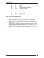
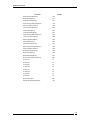
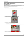
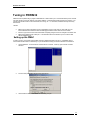
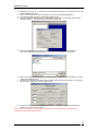
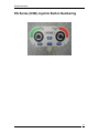
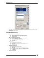
DS-Series
User Manual
The Leader in 3D Scanning since 1987
February 2009
All Rights Reserved
Laser Design Inc.
DS-Series User Guide
This page left intentionally blank
This page left intentionally blank
2
DS-Series User Guide
SYSTEM TYPES ...........................................................................................................................................................5
PMAC I AND PMAC II ISA SYSTEMS....................................................................................................................... 5
Overview.....................................................................................................................................................................5
PMAC I Systems........................................................................................................................................................5
PMAC II Systems ......................................................................................................................................................6
RUNNING SSC AND PEWIN........................................................................................................................................ 8
Process 1: Simplest Process- Requires User intervention to switch between PWin32 and SSC:...............8
PROCESS 2:- SETUP SYSTEM TO HAVE PCOM32 SYSTEM SERVICE START MANUALLY...................................... 8
TUNING IN PEWIN32................................................................................................................................................... 9
Setting up the PMAC................................................................................................................................................9
Motion Commands..................................................................................................................................................10
Servo Tuning............................................................................................................................................................13
PMAC PC104 (USB) SYS TEMS .............................................................................................................................15
PMAC PC104 SYSTEMS............................................................................................................................................ 15
Hardware Wiring....................................................................................................................................................15
PMAC CONFIGURATION .....................................................................................................................................16
PMAC I AND PMACII ............................................................................................................................................... 16
PC 104.......................................................................................................................................................................... 16
TUNING IN PEWIN32 ..............................................................................................................................................17
SETTING UP THE PMAC............................................................................................................................................. 17
M OTION COMMANDS.................................................................................................................................................. 18
PMAC PC104 with Blended Moves Disabled (Older PMAC Firmware) .....................................................18
PMAC PC104 with Blended Moves Enabled.....................................................................................................19
PMACII.....................................................................................................................................................................19
SERVO TUNING............................................................................................................................................................ 20
BLENDED MOVES PMAC UPDATE..................................................................................................................22
DS-SERIES (USB) JOYSTICK BUTTON NUMBERING..............................................................................27
BASIC GEOMET COMMANDS FOR SURVEYOR SETUP............................................................................................. 28
Every time you restart PC:....................................................................................................................................28
Every time you open a new window:...................................................................................................................28
BALL BAR M EASUREMENT (REPEATABLE IN BOTH DIRECTIONS TO .0001”-.0002” .0002” IS SPEC)............. 28
GAUGE BLOCK M EASUREMENT................................................................................................................................ 28
REPEATABILITY TEST (SPEC IS RANGE <.00024”, TYPICAL RESULTS ARE <.0001")......................................... 29
If using Geomet 301 or 101+................................................................................................................................29
If using Geomet Jr or 101:....................................................................................................................................29
M ACHINE A DJUSTMENTS FOR SQUARENESS ........................................................................................................... 29
XY Adjustments: ......................................................................................................................................................30
YZ Adjustments........................................................................................................................................................30
XZ Adjustments........................................................................................................................................................30
GEOMET TROUBLESHOOTING.................................................................................................................................... 30
GEOMET LE SOFTWARE.....................................................................................................................................31
M ACHINE CALIBRATION IN GEOMET LE (LIMITED EDITION).............................................................................. 31
Every time you restart PC:....................................................................................................................................31
Every time you open a new window:...................................................................................................................31
Ball Bar Measurement (Repeatable in both directions to .0001”-.0002” .0002” is spec)........................31
Gauge Block Measurement...................................................................................................................................33
Repeatability Measurement...................................................................................................................................34
DS-SERIES MAINTENANCE ................................................................................................................................35
LEVELING YOUR M ACHINE BASE : ........................................................................................................................... 35
3
DS-Series User Guide
CLEANING THE M ACHINE COVERS AND PLATE STAND:....................................................................................... 35
COVER AND BELLOWS REMOVAL AND REPLACEMENT :....................................................................................... 35
M AINTAINING THE GRANITE SURFACE PLATE:...................................................................................................... 35
CLEANING THE GRANITE SURFACE PLATE:............................................................................................................ 35
M AINTAINING GROUND SURFACES:......................................................................................................................... 36
M AINTAINING THE PROBE BAR: ............................................................................................................................... 36
SCALES AND ENCODER HEADS:................................................................................................................................ 36
BEARINGS : ................................................................................................................................................................... 36
COUNTER BALANCE A DJUSTMENT :......................................................................................................................... 36
LOCKS AND FINE ADJUSTMENT (DM-SERIES ONLY):........................................................................................... 36
W HAT TO DO IF YOU ‘CRASH ’ YOUR SYSTEM (DS-SERIES): ................................................................................ 36
TROUBLESHOOTING REPEATABILITY PROBLEMS .............................................................................37
TYPICAL GEOMET CONFIGURATION..........................................................................................................38
4
DS-Series User Guide
System Types
PMAC I and PMAC II ISA Systems
Overview
Older version DS Series machines are identified by their characteristic Joystick. The older joystick employs an LCD
display, which can display various controller messages for the user. In order to utilize this joystick, instead of the newer
version, the PMAC Motion Control card stores a different version of PLC firmware than the new version, and therefore
requires a separate driver. This driver is called DS Series (LCD joystick) Motion Control.
The older joystick also requires the use of an ISA motion control card. This system supports both PMAC I and PMAC II
ISA control cards. In addition, this system requires that the PC be setup as dual boot to support both the Windows 98 and
Windows 2000 operating systems. Surveyor Scan Control is best used under Windows 2000, but PMAC support
software, including Geomet for the touch probe interface, only run in Windows 98.
The main requirement of the LCD Joystick style machines is the need to autophase the motors when starting the
hardware. This process ensures that the system knows what direction the stages are moving when it receives encoder
readings. When you first start up the machine, the joystick should emit a long beep, then display the text "Press the red
stop button to autophase the motors". When you press the red button on the joystick, each axis will make a quick back
and forth move to complete the autophase procedure. Then the motors will shut down.
It is important to remember that Surveyor Scan Control will not launch if the motors have not been autophased for
PMACII systems. Also, if the motion control hardware shuts down due to a crash, it can be necessary to rephase the
motors. To do this, hold down the F1, Clear, and F5 buttons on the joystick simultaneously. This will restart the PLCs
and cause the joystick to beep as though the machine were first starting up.
PMAC I Systems
PMAC I systems support 3 axes, and require an ISA controller card inside the PC. These systems are generally used to
support belt drive motors; they do not support linear motors. Existing systems use the Sensoray interface for Encoder
Latching; however they can easily be upgrade to the HUE if desired. Hardware wiring highlights are summarized below.
Hardware Wiring
1)
The PMAC I ISA card connects to the hardware interconnect card inside the machine's electrical cabinet via 4 ribbon
cables and 1 power cable.
5
DS-Series User Guide
2)
3)
4)
5)
6)
Each of these cables connects to the interconnect card as shown above. Both cables and plugs are clearly marked
and keyed, so that there is no confusion over where to plug things in.
The encoder interface resides between the interconnect card and the bulkhead.
a) Encoder cables from the 3 axes are routed from the bulkhead to the Sensoray breakout board (or HUE).
b) These cables populate channels 1 through 3 of the breakout board.
c) The encoder signals pass through the breakout board to cables, which are routed to the interconnect card.
d) The breakout board connects to the Sensoray PCI card via a single 26 pin ribbon cable and to the laser VP
board (in the PC's ISA slot) via a DB9 cable.
Motor wiring runs through the three amplifiers, then to the bulkhead.
All cables from the machine base plug directly into labeled connectors on the bulkhead of the electrical cabinet.
If you wish to install a 4th axis on a PMAC I machine, a separate controller such as an ESP 300 is required.
PMAC II Systems
PMAC II systems support up to 4 axes, and require an ISA controller card inside the PC. These systems are generally
used to support linear motors; they also support belt drive motors. Existing systems use the Sensoray interface for
Encoder Latching; however they can easily be upgrade to the HUE if desired. Hardware wiring highlights are summarized
below.
Hardware Wiring
1)
2)
The PMAC II ISA card connects to the hardware interconnect cards via 5 ribbon cables, a power cable and a joystick
cable.
Two of the ribbon cables are high dens ity 100 pin ribbon cables, which connect to the IOF cards shown below. The
connection to the IOF cards is very fragile, so care must be taking when plugging in the ribbon cables, not to bend
any leads.
6
DS-Series User Guide
3)
The remaining cables connect to the interconnect c ard as shown below. Both cables and plugs are clearly marked
and keyed, so that there is no confusion over where to plug things in.
The encoder interface resides between the interconnect card and the bulkhead.
a) Encoder cables from the 3 axes are routed from the bulkhead to the Sensoray breakout board (or HUE).
b) These cables populate channels 1 through 3 of the breakout board.
c) The encoder signals pass through the breakout board to cables, which are routed to the interconnect card.
d) The breakout board connects to the Sensoray PCI card via a single 26 pin ribbon cable and to the laser VP
board (in the PC's ISA slot) via a DB9 cable.
4)
5)
6)
7)
Motor wiring runs through the amplifiers, then to the bulkhead.
All cables from the machine base plug directly into labeled connec tors on the bulkhead of the electrical cabinet.
If you wish to install a 4th axis on a PMAC II machine, you need only plug into the motor and encoder plugs on the
bulkhead, and then update the PMAC PLC code (the PLC code will be provided with your rotary table).
7
DS-Series User Guide
Running SSC and PEWIN
With PMAC II systems, 2 separate device drivers are required in order to communicate to the PMAC card. For Delta Tau
base programs like PEWIN and Geomet, the driver is called PCOM32. For SSC, the driver is called GenIODFC. Both
drivers must be set to the card's I/O address, which is 0210 through 021F. This means that they can not operate at the
same time. So switching between SSC and PEWIN or Geomet requires loading and unloading the device drivers. Below
are two methods of doing this.
Process 1: Simplest Process- Requires User intervention to switch between
PWin32 and SSC:
1.
2.
3.
4.
5.
6.
7.
Open Windows Device Manager
Sort by 'Resource By Connection'
Find '0210-021F' in the I/O folder
Right click on and uninstall (it will be labeled PMAC ISA Motion Control or GENIO)
To go to SSC
a. Run Surveyor Motion Control Hardware Setup
b. Restart the PC
c. Start SSC
To go to PEWin
a. Run PEWin exe file
b. Reconfigure properties to use the PMAC card
Repeat process using either step 5 or step 6 to return to previous state.
Process 2:- Setup system to have PCom32 System Service start
manually
1.
2.
3.
Install PEWin 1.7 (If using a newer version, uninstall first.)
Run Motion.exe from the program menu
When Prompted configure the PCom32 Service to start manually (this prevents the conflict since the service will
only start when SSC or PEWin attempts to access.
8
DS-Series User Guide
Tuning in PEWIN32
PMAC firmware is updated using a program called PEWin32. PEWin allows you to communicate directly to the controller
card, and change PLC program settings, query status variables, or upload and download complete PLC programs. You
can also perform basic motion control commands, servo tuning, etc... For this reason, PEWin should only be used by
trained users.
NOTES:
•
•
•
Before trying to load configurations, export configurations be sure to type 'CTRL+K' and 'CTRL+D' in the
terminal window which will kill the motors and disengage the PMAC card to allow full communication.
Be sure to type 'Save' in the terminal window after completing changes to save the changes to the PMAC card.
Before exiting PeWin32 type 'enable plc 1' in the terminal window which will allow you to run SSC or SMC
without restarting the PC.
Setting up the PMAC
In order to properly communicate with the PMAC controller, PEWIN first needs to be set up. PEWIN likely will not
communicate with the PMAC on initial startup, so you should follow this setup procedure to initialize communications.
1.
Launch PEWIN32. You should see an interface like the one below. Close any open Terminal or Position
Windows.
2.
From the Setup menu, select General Setup and Options.
3.
Click the Select button, and the PMAC Devices dialog will open.
5.
Select the PMAC 0 Device, then click Insert.
9
DS-Series User Guide
6.
When the Available PMAC devices dialog open, you should see "PMAC USB0" or a similar device
listed. Select it and click OK.
7.
When you return to the PMAC Devices dialog, the PMAC USB0 device should be listed under device 0. Click
OK at the next 2 dialogs.
Finally, select Terminal from the View menu to open the terminal window.
8.
9. Also, from the View menu, select Position, to open the Position window.
10. Right click inside the position window, and select Follow Error from the menu. This will display the following
error.
Motion Commands
To perform servo tuning, it is necessary to command moves. Doing this in PEWIN requires the setting of a few variables
and issuing commands in the terminal window. The typical sequence for performing motion commands is as follows:
PMAC PC104 with Blended Moves Disabled (Older PMAC Firmware)
1.
2.
3.
4.
5.
6.
7.
Turn the motors on by keying in m759=47.
Next, home the stages. Set M759=49.
Before any move commands can be executed, you must set the machine to LDI mode. Set M759=39.
To make a move, first define the move speed in inches per second. Set m895=.5, for example to make moves
at .5 inches per second.
Set the X, Y, and Z move destinations by setting M891, M892, and M893 to position values in inches based
upon the home position.
Execute the move from step 5 by setting M890=1.
Repeat steps 5 and 6 for successive moves. If you do not update a specific axis' position value, it will stay the
same for the next move. That way you can easily make single axis moves.
Command
Value
Result
M759
47
Motors On
10
DS-Series User Guide
M759
48
Motors Off
M759
49
Home
M759
39
LDI Mode (required before issuing M890=1)
M895
Input
Speed in Inches per Second
M891
Input
X position in Inches
M892
Input
Y position in Inches
M893
Input
Z position in Inches
M894
Input
R Position in Degrees
M890
1
Start move
PMAC PC104 with Blended Moves Enabled
1.
2.
3.
4.
5.
6.
7.
8.
9.
Turn the motors on by keying in m759=47.
Next, home the stages. Set M759=49.
Before any move commands can be executed, you must set the machine to LDI mode. Set M759=39.
To make a move, first define the move speed in inches per second. Set m895=.5, for example to make moves
at .5 inches per second.
Next, set the system to make a linear stage or rotary move. Set M894=0 for Linear moves, and M894=1 for
rotary moves.
Set the X, Y, and Z move destinations by setting M891, M892, and M893 to position values in inches based
upon the home position. M891 will set either the X position or the R position depending on the value of M894.
When Blended Moves in enabled, you chain multiple moves together. Moves must be written to a buffer. For
each move group, set M899=1 to write the move to the buffer.
Execute the move from step 5 by setting M890=1.
Repeat steps 5 through 7 for successive moves. If you do not update a specific axis' position value, it will stay
the same for the next move. That way you can easily make single axis moves.
11
DS-Series User Guide
Command
Value
Result
M759
47
Motors On
M759
48
Motors Off
M759
49
Home
M759
39
LDI Mode (required before issuing M890=1)
M895
Input
Speed in Inches per Second/Degrees Per Second
M894
0/1
0=Linear XYZ Move, 1=Rotary R move
M891
Input
X position in Inches/R Position in Degrees
M892
Input
Y position in Inches
M893
Input
Z position in Inches
M899
1
Writes the position variables to the buffer
M890
1
Start move
PMACII
1.
2.
3.
4.
5.
6.
7.
Turn the motors on by keying in m751=47.
Next, home the stages. Set M751=49.
Before any move commands can be executed, you must set the machine to LDI mode. Set M751=39.
To make a move, first define the move speed in inches per second. Set m895=.5, for example to make moves
at .5 inches per second.
Set the X, Y, and Z move destinations by setting M891, M892, and M893 to position values in inches based
upon the home position.
Execute the move from step 5 by setting M890=1.
Repeat steps 5 and 6 for successive moves. If you do not update a specific axis' position value, it will stay the
same for the next move. That way you can easily make single axis moves.
Command
Value
Result
M751
47
Motors On
M751
48
Motors Off
M751
49
Home
M751
39
LDI Mode (required before issuing M890=1)
M895
Input
Speed in Inches per Second
M891
Input
X position in Inches
M892
Input
Y position in Inches
M893
Input
Z position in Inches
M894
Input
R Position in Degrees
M890
1
Start move
12
DS-Series User Guide
Servo Tuning
In general, your machine should already be tuned. Changes in tuning may result over time from environmental changes
such as temperature and humidity, or from mechanical wear and tear. Typical symptoms of suspect tuning are vibration
of the stages, or the machine hanging at the end of scan passes. Vibration usually indicates an issue with the Damping
parameter, while system hangs are generally a result of the machine not getting into position in a timely manner. Both
conditions can be improved through tuning. Below is a list of tuning parameters and their function.
1.
Proportional Gain: This is the main tuning parameter. Increasing the Proportional Gain will tend to decrease
following error (during a move) and in position error (after a move is complete). Increasing this parameter too
much can lead to instability and oscillation.
2. Integral Gain: This parameter can be used for fine tuning the in position error. The goal of tuning is reduce the
in position error to a minimum. Increasing the Integral gain can aid in making sure the axis moves all the way to
its intended position, and does not overshoot. Using too much Integral Gain can cause position dithering
around the final move position.
3. Derivative Gain or Damping: This parameter can be used to dampen high frequency oscillations that may have
been introduced by increasing the P or I values. Too much damping can also cause vibrations.
4. Velocity Feed Forward: This term can be used to reduce the following error during a move. Too much VFF and
the following error will change direction and increase.
Tuning is an iterative process, and requires you to command a move or two after every change in order to verify your
results. When starting from scratch, increase the P value slightly (10% increments) while commanding moves. Try to
reduce the following and position errors as much as possible without introducing vibration. Next, move on to the I
value. Increase this value to dial in the in position error to as near to zero as possible. If vibration is introduced, you can
add some damping. Finally, to tighten up the motion and reduce following error during moves, increase the VFF.
If you are trying to fix an existing tuning problem, then make minor changes only. Make changes to only one parameter at
a time. For in position problems, start by increasing the I value. If this does not increase vibration, you can keep
adjusting the value. If the changes are not enough to solve the problem, then you may want to increase the P value
first. Set I back to its original value, and start adjusting P. If vibration is your problem, try adjusting the D value
first. Always reduce it before increasing it, and check the vibration during a move. If it gets worse, change it in the other
direction. If changing D doesn't help, you probably need to reduce the P value.
If you are having problems with in position one final resort is to increase the In Position Tolerance for the given axis. This
tells the motion controller when the axis is Close enough. Adjust the Ix28 variables for in position tolerance. This variable
is set in unit of encoder counts times 16. So to set the tolerance to 0.001", you would enter a value of approximately 812.
13
DS-Series User Guide
Parameter
Variable
X-Axis Proportional Gain (P)
I130
X-Axis Integral Gain (I)
I133
X-Axis Derivative Gain (D)
I131
X-Axis Velocity Feed Foreword (V)
I132
X Axis In Position Tolerance
I128
Y-Axis Proportional Gain (P)
I230
Y-Axis Integral Gain (I)
I233
Y-Axis Derivative Gain (D)
I231
Y-Axis Velocity Feed Foreword (V)
I232
Y-Axis In Position Tolerance
I228
Z-Axis Proportional Gain (P)
I330
Z-Axis Integral Gain (I)
I333
Z-Axis Derivative Gain (D)
I331
Z-Axis Velocity Feed Foreword (V)
I332
Z Axis In Position Tolerance
I328
R-Axis Proportional Gain (P)
I430
R-Axis Integral Gain (I)
I433
R-Axis Derivative Gain (D)
I431
R-Axis Velocity Feed Foreword (V)
I432
-X Soft Limit
P1
+X Soft Limit
P2
-Y Soft Limit
P3
+Y Soft Limit
P4
-Z Soft Limit
P5
+Z Soft Limit
P6
-R Soft Limit
P7
+R Soft Limit
P8
R-Axis Home Offset
P85
Joystick Pot Dead-band (all axis)
P34
14
DS-Series User Guide
PMAC PC104 (USB) Systems
PMAC PC104 Systems
PMAC PC104 systems support 5 axes, reside outside the PC and connect to the PC via a USB 1.1 cable. These systems
are generally used to support belt drive motors; they do not support linear motors. Existing systems use the HUE
interface for Encoder Latching. Hardware wiring highlights are summarized below.
Hardware Wiring
1)
The PMAC PC104 interface connects to the PC via a USB cable, with another USB cable required for the joystick
interface. If your PC supports only 2 USB connections, route the joystick USB cable to the USB hub on the HUE
box.
2)
Motor cables and the DB9 cable from the machine joystick connect directly to the PC104.
3)
The encoder interface resides between the interconnect card and the bulkhead.
a) Encoder cables from the 3 axes are routed from the bulkhead to the HUE.
b) These cables populate channels 1 through 3 of the HUE.
c) The encoder signals pass through the HUE to cables, which are routed to the PC104.
d) The HUE connects to the PC via a USB cable and to the laser VP board (in the PC's ISA slot) via a DB9 cable.
4)
5)
Cables from the machine base plug directly into labeled connectors on the bulkhead of the PC104.
If you wish to install a 4th axis on a PMAC PC104 machine, a separate controller such as an ESP 300 is required.
15
DS-Series User Guide
PMAC Configuration
On newer DS Series systems, the PMAC Device Configuration utility launches when starting Surveyor Scan Control
each time the PMAC code has been updated. You must properly configure the PMAC to communicate each time. The
original configuration settings are remembered each time the utility launches, so other than the first time the utility
launches, you can simply click OK when prompted.
PMAC I and PMACII
1.
2.
3.
Select In PC Bus for the Device Location.
Select 0x210 for the Port Address.
Set both Interrupt Adr and DPRAM Adr to None.
PC 104
1.
2.
3.
Select In PC Bus for the Device Location.
Select USB for the Port Address.
Set both Interrupt Adr and DPRAM Adr to None.
16
DS-Series User Guide
Tuning in PEWIN32
PMAC firmware is updated using a program called PEWin32. PEWin allows you to communicate directly to the controller
card, and change PLC program settings, query status variables, or upload and download complete PLC programs. You
can also perform basic motion control commands, servo tuning, etc... For this reason, PEWin should only be used by
trained users.
NOTES:
•
•
•
Before trying to load configurations, export configurations be sure to type 'CTRL+K' and 'CTRL+D' in the
terminal window which will kill the motors and disengage the PMAC card to allow full communication.
Be sure to type 'Save' in the terminal window after completing changes to save the changes to the PMAC card.
Before exiting PeWin32 type 'enable plc 1' in the terminal window which will allow you to run SSC or SMC
without restarting the PC.
Setting up the PMAC
In order to properly communicate with the PMAC controller, PEWIN first needs to be set up. PEWIN likely will not
communicate with the PMAC on initial startup, so you should follow this setup procedure to initialize communications.
1.
Launch PEWIN32. You should see an interface like the one below. Close any open Terminal or Position
Windows.
2.
From the Setup menu, select General Setup and Options.
3.
Click the Select button, and the PMAC Devices dialog will open.
17
DS-Series User Guide
5.
Select the PMAC 0 Device, then click Insert.
6.
When the Available PMAC devices dialog open, you should see "PMAC USB0" or a similar device
listed. Select it and click OK.
7.
When you return to the PMAC Devices dialog, the PMAC USB0 device should be listed under device 0. Click
OK at the next 2 dialogs.
Finally, select Terminal from the View menu to open the terminal window.
8.
9. Also, from the View menu, select Position, to open the Position window.
10. Right click inside the position window, and select Follow Error from the menu. This will display the following
error.
Motion Commands
To perform servo tuning, it is necessary to command moves. Doing this in PEWIN requires the setting of a few variables
and issuing commands in the terminal window. The typical sequence for performing motion commands is as follows:
PMAC PC104 with Blended Moves Disabled (Older PMAC Firmware)
1.
2.
3.
Turn the motors on by keying in m759=47.
Next, home the stages. Set M759=49.
Before any move commands can be executed, you must set the machine to LDI mode. Set M759=39.
18
DS-Series User Guide
4.
5.
6.
7.
To make a move, first define the move speed in inches per second. Set m895=.5, for example to make moves
at .5 inches per second.
Set the X, Y, and Z move destinations by setting M891, M892, and M893 to position values in inches based
upon the home position.
Execute the move from step 5 by setting M890=1.
Repeat steps 5 and 6 for successive moves. If you do not update a specific axis' position value, it will stay the
same for the next move. That way you can easily make single axis moves.
Command
Value
Result
M759
47
Motors On
M759
48
Motors Off
M759
49
Home
M759
39
LDI Mode (required before issuing M890=1)
M895
Input
Speed in Inches per Second
M891
Input
X position in Inches
M892
Input
Y position in Inches
M893
Input
Z position in Inches
M894
Input
R Position in Degrees
M890
1
Start move
PMAC PC104 with Blended Moves Enabled
1.
2.
3.
4.
5.
6.
7.
8.
9.
Turn the motors on by keying in m759=47.
Next, home the stages. Set M759=49.
Before any move commands can be executed, you must set the machine to LDI mode. Set M759=39.
To make a move, first define the move speed in inches per second. Set m895=.5, for example to make moves
at .5 inches per second.
Next, set the system to make a linear stage or rotary move. Set M894=0 for Linear moves, and M894=1 for
rotary moves.
Set the X, Y, and Z move destinations by setting M891, M892, and M893 to position values in inches based
upon the home position. M891 will set either the X position or the R position depending on the value of M894.
When Blended Moves in enabled, you chain multiple moves together. Moves must be written to a buffer. For
each move group, set M899=1 to write the move to the buffer.
Execute the move from step 5 by setting M890=1.
Repeat steps 5 through 7 for successive moves. If you do not update a specific axis' position value, it will stay
the same for the next move. That way you can easily make single axis moves.
Command
Value
Result
M759
47
Motors On
M759
48
Motors Off
M759
49
Home
M759
39
LDI Mode (required before issuing M890=1)
M895
Input
Speed in Inches per Second/Degrees Per Second
M894
0/1
0=Linear XYZ Move, 1=Rotary R move
M891
Input
X position in Inches/R Position in Degrees
M892
Input
Y position in Inches
M893
Input
Z position in Inches
M899
1
Writes the position variables to the buffer
M890
1
Start move
PMACII
1.
2.
3.
Turn the motors on by keying in m751=47.
Next, home the stages. Set M751=49.
Before any move commands can be executed, you must set the machine to LDI mode. Set M751=39.
19
DS-Series User Guide
4.
5.
6.
7.
To make a move, first define the move speed in inches per second. Set m895=.5, for example to make moves
at .5 inches per second.
Set the X, Y, and Z move destinations by setting M891, M892, and M893 to position values in inches based
upon the home position.
Execute the move from step 5 by setting M890=1.
Repeat steps 5 and 6 for successive moves. If you do not update a specific axis' position value, it will stay the
same for the next move. That way you can easily make single axis moves.
Command
Value
Result
M751
47
Motors On
M751
48
Motors Off
M751
49
Home
M751
39
LDI Mode (required before issuing M890=1)
M895
Input
Speed in Inches per Second
M891
Input
X position in Inches
M892
Input
Y position in Inches
M893
Input
Z position in Inches
M894
Input
R Position in Degrees
M890
1
Start move
Servo Tuning
In general, your machine should already be tuned. Changes in tuning may result over time from environmental changes
such as temperature and humidity, or from mechanical wear and tear. Typical symptoms of suspect tuning are vibration
of the stages, or the machine hanging at the end of scan passes. Vibration usually indicates an issue with the Damping
parameter, while system hangs are generally a result of the machine not getting into position in a timely manner. Both
conditions can be improved through tuning. Below is a list of tuning parameters and their function.
1.
Proportional Gain: This is the main tuning parameter. Increasing the Proportional Gain will tend to decrease
following error (during a move) and in position error (after a move is complete). Increasing this parameter too
much can lead to instability and oscillation.
2. Integral Gain: This parameter can be used for fine tuning the in position error. The goal of tuning is reduce the
in position error to a minimum. Increasing the Integral gain can aid in making sure the axis moves all the way to
its intended position, and does not overshoot. Using too much Integral Gain can cause position dithering
around the final move position.
3. Derivative Gain or Damping: This parameter can be used to dampen high frequency oscillations that may have
been introduced by increasing the P or I values. Too much damping can also cause vibrations.
4. Velocity Feed Forward: This term can be used to reduce the following error during a move. Too much VFF and
the following error will change direction and increase.
Tuning is an iterative process, and requires you to command a move or two after every change in order to verify your
results. When starting from scratch, increase the P value slightly (10% increments) while commanding moves. Try to
reduce the following and position errors as much as possible without introducing vibration. Next, move on to the I
value. Increase this value to dial in the in position error to as near to zero as possible. If vibration is introduced, you can
add some damping. Finally, to tighten up the motion and reduce following error during moves, increase the VFF.
If you are trying to fix an existing tuning problem, then make minor changes only. Make changes to only one parameter at
a time. For in position problems, start by increasing the I value. If this does not increase vibration, you can keep
adjusting the value. If the changes are not enough to solve the problem, then you may want to increase the P value
first. Set I back to its original value, and start adjusting P. If vibration is your problem, try adjusting the D value
first. Always reduce it before increasing it, and check the vibration during a move. If it gets worse, change it in the other
direction. If changing D doesn't help, you probably need to reduce the P value.
If you are having problems with in position one final resort is to increase the In Position Tolerance for the given axis. This
tells the motion controller when the axis is Close enough. Adjust the Ix28 variables for in position tolerance. This variable
is set in unit of encoder counts times 16. So to set the tolerance to 0.001", you would enter a value of approximately 812.
20
DS-Series User Guide
Parameter
Variable
X-Axis Proportional Gain (P)
I130
X-Axis Integral Gain (I)
I133
X-Axis Derivative Gain (D)
I131
X-Axis Velocity Feed Foreword (V)
I132
X Axis In Position Tolerance
I128
Y-Axis Proportional Gain (P)
I230
Y-Axis Integral Gain (I)
I233
Y-Axis Derivative Gain (D)
I231
Y-Axis Velocity Feed Foreword (V)
I232
Y-Axis In Position Tolerance
I228
Z-Axis Proportional Gain (P)
I330
Z-Axis Integral Gain (I)
I333
Z-Axis Derivative Gain (D)
I331
Z-Axis Velocity Feed Foreword (V)
I332
Z Axis In Position Tolerance
I328
R-Axis Proportional Gain (P)
I430
R-Axis Integral Gain (I)
I433
R-Axis Derivative Gain (D)
I431
R-Axis Velocity Feed Foreword (V)
I432
-X Soft Limit
P1
+X Soft Limit
P2
-Y Soft Limit
P3
+Y Soft Limit
P4
-Z Soft Limit
P5
+Z Soft Limit
P6
-R Soft Limit
P7
+R Soft Limit
P8
R-Axis Home Offset
P85
Joystick Pot Dead-band (all axis)
P34
21
DS-Series User Guide
Blended Moves PMAC Update
Occasionally it maybe necessary to update your systems PMAC code to take advantage of new features. Below are the
instructions for updating your PMAC code that will allow both coordinated and blended moves dramatically decreasing
scan time. This upgrade is for DS (USB)-Series customers only. It requires four new PLC motion control files to
complete. Please see your LDI representative for these files before proceeding. (m931.pmc, PLC6.pmc, PLC9.pmc, and
Prog30.pmc)
Your system should have a program called PEWin32. PEWin allows you to communicate directly to the controller card,
and change PLC program settings, query status variables, or upload and download complete PLC programs. You can
also perform basic motion control commands, servo tuning, etc... For this reason, PEWin should only be used by trained
users or follow the directions below exactly. Please review the instructions in their entirety before proceeding. Contact
your LDI representative to eliminate any questions before proceeding or arrange for an LDI representative to complete
this upgrade.
In order to properly communicate with the PMAC controller, PEWIN first needs to be set up. PEWIN likely will not
communicate with the PMAC on initial startup, so you should follow this setup procedure to initialize communications.
1.
Launch PEWIN32. You should see an interface like the one below. Close any open Terminal or Position
Windows
2.
.
From the Setup menu, select General Setup and Options.
3.
Click the Select button, and the PMAC Devices dialog will open.
4.
Select the PMAC 0 Device, then click Insert.
22
DS-Series User Guide
5.
When the Available PMAC devices dialog open, you should see "PMAC USB0" or a similar device
listed. Select it and click OK.
6.
When you return to the PMAC Devices dialog, the PMAC USB0 device should be listed under device 0. Click
OK at the next 2 dialogs.
Finally, select Terminal from the View menu to open the terminal window.
7.
8.
9.
Click on the new terminal window and type 'CTRL+K' and hit 'Enter'. The text is entered in the bottom dialog box
(as shown above) and the result is displayed in the blue box above it.
Now enter type 'CTRL+D' and hit 'Enter'. Your terminal window should look like this if completed correctly.
23
DS-Series User Guide
10. At this point it is recommended to back up your current PMAC configuration. From the Back Up menu, select
'Upload Configuration'. Use check boxes as shown below and click 'OK'
11. The following dialog box will then appear. Save to a convenient backup location with a relevant file
name. Such as 'OriginalConfiguration11-14-04' so that it can be referenced in the future.
12. From the File Menu, select 'Open File...' option. The following dialog box will open.
24
DS-Series User Guide
13. This will then open a new dialog box. Browse to the location at which you have previously saved the four PLC
motion control Files and select the first one. (Order does not matter, just be sure that all four files are
downloaded.
14. The file will then open in a file manager. Select the download option (yellow error pointing down in screen shot
below) and verify that there were no errors. (The bottom left hand corner will stream the entries as they are
downloaded and when the last entry has completed there will be a message stating there were no errors. If
there were errors, you most likely did not use 'CTRL+K' and/or 'CTRL+D' in steps 9 and 10. You will have to
repeat the entire procedure.)
25
DS-Series User Guide
15. Repeat steps 12 through 14. You can either use the open exact process above or use the file open menu in the
file download dialog box above.
16. After you download all four plc motion control files, you can close the file download dialog box.
17. In the terminal window type 'Save' and verify that it worked correctly.
18. At this point it is recommended to back up your New PMAC configuration. From the Back Up menu, select
'Upload Configuration'. Use check boxes as shown below and click 'OK'
19. The following dialog box will then appear. Save to a convenient backup location with a relevant file
name. Such as 'BlendedMovesConfiguration11-14-04' so that it can be referenced in the future.
20. Before exiting PeWin32 type 'enable plc 1' in the terminal window and hit 'Enter'. This will allow you to run SSC
or SMC without restarting the PC.
21. The next time you attempt to start SMC or SSC, the PMAC card will have to be reconfigured. You will see the
following screen. Simply click on 'In PC Bus' and click ok.
22. You are now ready utilize blended and coordinated moves on your system. Please see the path planning
section on how to turn on for scan passes.
NOTE: it is also recommended to use 'Safe Z Moves' and/or 'Safe Transverse Moves' when using blended and
coordinated moves to prevent possible crashes.
26
DS-Series User Guide
DS-Series (USB) Joystick Button Numbering
27
DS-Series User Guide
Geomet 101/301 Software
Basic Geomet Commands for Surveyor Setup
Every time you restart PC:
1.
2.
3.
4.
5.
Open Geomet
Home Machine
Turn motors on
Home machine
Close dialogue window
Every time you open a new window:
1.
Qualify Stylus
a. Set known stylus to active, or create new
b. If creating new, click next and then touch five points on calibration sphere. (Top and four times on
side of sphere approx. every 90 degs)
a. NOTE: you can also use the auto calibrate feature by selecting the auto calibrate
option. Follow the instructions and take a single point on the top of the sphere. The
software will then run a DCC mode stylus calibration.
c. Set to active
Ball Bar Measurement (Repeatable in both directions to .0001”.0002” .0002” is spec)
1.
2.
3.
4.
5.
6.
7.
8.
9.
10.
11.
12.
13.
14.
Shift ICS to PCS by hitting Shift + "
Make sure you are in Polar Coordinate System (‘E’ toggles systems)
‘V’ to measure sphere
Select ‘O.D.’ with mouse or number pad
Teach probe the probe path
Use the ‘IP’ button on the joystick to set Intermediate Positions
Hit the sphere in 5 positions, same as qualifying stylus
Make ‘IP’ above ball bar
Hit 5 positions on second sphere
Make ‘IP above final ball
Turn Motors on using the ‘motor on’ button on the joystick
‘S’ to measure point to point distance
‘Save As’ to some file name
‘Run’ for Geomet to complete measurement in DCC mode.
Gauge Block Measurement
1.
2.
3.
4.
5.
Setup a plane on the top of the gauge block
a. ‘B’ key for setting up a plane
b. Take four points on the top of the gauge block (four corners)
c. ‘J’ key to orient plane
d. ‘L’ key to make origin
Setup a line on the side of the gauge block
a. 1From the measure menu, select ‘point’
b. Using mouse or number pad, select what type of point (-X, etc...)
c. Take 2 points on the side of the gauge block
d. ‘K’ key to align
e. ‘L’ key to make origin
Setup a point
a. From the measure menu, select ‘point’
b. Using mouse or number pad, select what type of point (-Y, etc…)
c. Take 1 point
d. ‘L’ key to make origin
Geomet will now say PCS done
Measure length of gauge block
a. From the measure menu, select ‘point’
b. Using mouse or number pad, select what type of point (-Y, etc…)
c. Take 1 point
d. Using number pad, select what type of point (opposite of previous)
e. Take 1 point on opposite side of previous
28
DS-Series User Guide
6.
7.
f.
‘S’ for distance
‘Save As’ to some file name
‘Run’ to run routine in DCC mode.
Repeatability Test (Spec is range <.00024”, typical results are
<.0001")
If using Geomet 301 or 101+
1.
2.
3.
4.
5.
6.
7.
8.
9.
10.
11.
12.
13.
14.
15.
16.
17.
18.
19.
20.
21.
22.
23.
24.
25.
26.
27.
28.
29.
30.
31.
32.
Shift ICS to PCS by hitting Shift + '
V to measure sphere
6 to take OD of sphere
Take 5 points (top and 4 sides)
L to set to origin
Return three times to set X, Y, and Z
Shift + L to get to FCS manager
Create some new FCS, append, and remember FCS number
Start new session (don't need to save previous session)
“to select the Coordinate System Manager.
Click on FCS
Select the coordinate system from step 7.
V to measure sphere
6 to take OD of sphere
Take 5 points (top and 4 sides) (be sure to teach probe path using IP's to prevent crashes while running in DCC
mode)
Go to GEO-PLUS drop down menu and select Libraries
Click on Extract
Click on '3 OD ...' from the display window (the step which you measured the OD of the sphere above)
Type in a name for this sphere.
Click Export
Highlight the name given in step 17 and click Insert
Insert the number 9 on the bottom of the window.
Close window
Press the ~ key
Select all of the OD measurements (hold shift key while clicking top and bottom entries)
Click Fx option
Select Spread
Close window
Save program
Run Program
Record results.
Repeat a couple times to verify repeatability.
If using Geomet Jr or 101:
1.
2.
3.
4.
5.
6.
7.
8.
9.
10.
11.
12.
13.
14.
Shift ICS to PCS by hitting Shift + '
V to measure sphere
6 to take OD of sphere
Take 5 points on outside of sphere; be sure to teach probe path using IP's to prevent crashes while running in
DCC mode.
Repeat steps 2-3 at least 9 more times.
Press the ~ key
Select all of the OD measurements (hold shift key while clicking top and bottom entries)
Click Fx option
Select Spread
Close window
Save File
Run File
Record results.
Repeat a couple times to verify repeatability.
Machine Adjustments for Squareness
NOTE: Adjustments are sensitive and should not be completed by anyone other than a Laser Design Inc
engineer or Laser Design Approved Personnel.
29
DS-Series User Guide
XY Adjustments:
Loosen three bolts on inboard side of bridge. Break loose and then re-tighten. Use set screws on inside of 90 on bridge to
adjust. Re-tighten bolts when done.
YZ Adjustments
Adjust Z-axis bearings on top of bridge. Use set screws to free concentric bearings. Adjust both sides. Be sure ‘bearing
skid test’ still works after adjustment.
XZ Adjustments
Adjust Z-axis bearings on top of bridge. Use set screws to free concentric bearings. Adjust both sides. Be sure ‘bearing
skid test’ still works after adjustment.
Geomet Troubleshooting
•
•
The probe tip autocalibration routine fails after you manual take the first point and the software fails to take the
next point.
• Verify the motors are on.
• Verify the GEOMET configuration. Go to System->System Options-> CMM Characteristics->
Reverse Vector; verify that the check box is on.
System is acting peculiar
• Restart GEOMET
• Cycle power for the entire system
30
DS-Series User Guide
Geomet LE Software
Machine Calibration in Geomet LE (Limited Edition)
Every time you restart PC:
1.
2.
3.
4.
5.
Open Geomet
Home Machine
Turn motors on
Home machine
Close dialogue window
Every time you open a new window:
1.
Qualify Stylus
a.
b.
c.
Set known stylus to active, or create new
If creating new, click next and then touch five points on calibration sphere. (Top and four times on
side of sphere approx. every 90 degs)
a. NOTE: you can also use the auto calibrate feature by selecting the auto calibrate
option. Follow the instructions and take a single point on the top of the sphere. The
software will then run a DCC mode stylus calibration.
Set to active
Ball Bar Measurement (Repeatable in both directions to .0001”-.0002”
.0002” is spec)
1.
After Qualifying the stylus, select Ball Bar Macro from the Toolbar.
31
DS-Series User Guide
2.
3.
Teach the positions of both spheres using 5 points for each sphere. Be sure to set Intermediate Points between
touch probe hits using the IP button on the joystick. Always place an Intermediate Point at a safe location
between the 2 spheres when starting.
When the Wizard is finished, right click the entry for Ball bar Distance, and select Copy and Append... from the
pop up menu.
4.
Enter the number of samples you wish to add. If you add 4 Features, Geomet LE will measure the ball bar 5
times.
5.
6.
Geomet will create 4 new Ball Bar distance Features.
Select them all, and then click the "~" key.
7.
8.
In the Feature Selection dialog, select the fx button.
You can select any of the math functions to perform. Typically you will want to report the Average and Spread
of the 5 runs.
32
DS-Series User Guide
9.
When ready, click the Run button, and the program will run. It will report the Average and Spread for the 5 ball
bar repetitions.
10. You can print the results if you like.
Gauge Block Measurement
1.
2.
3.
4.
5.
6.
7.
Setup a plane on the top of the gauge block
a. ‘B’ key for setting up a plane
b. Take four points on the top of the gauge block (four corners)
c. ‘J’ key to orient plane
d. ‘L’ key to make origin
Setup a line on the side of the gauge block
a. 1From the measure menu, select ‘point’
b. Using mouse or number pad, select what type of point (-X, etc...)
c. Take 2 points on the side of the gauge block
d. ‘K’ key to align
e. ‘L’ key to make origin
Setup a point
a. From the measure menu, select ‘point’
b. Using mouse or number pad, select what type of point (-Y, etc…)
c. Take 1 point
d. ‘L’ key to make origin
Geomet will now say PCS done
Measure length of gauge block
a. From the measure menu, select ‘point’
b. Using mouse or number pad, select what type of point (-Y, etc…)
c. Take 1 point
d. Using number pad, select what type of point (opposite of previous)
e. Take 1 point on opposite side of previous
f.
‘S’ for distance
‘Save As’ to some file name
‘Run’ to run routine in DCC mode.
33
DS-Series User Guide
Repeatability Measurement
1.
2.
3.
4.
5.
6.
7.
8.
9.
10.
11.
12.
13.
14.
Shift ICS to PCS by hitting Shift + '
V to measure sphere
6 to take OD of sphere
Take 5 points on outside of sphere; be sure to teach probe path using IP's to prevent crashes while running in
DCC mode.
Repeat steps 2-3 at least 9 more times.
Press the ~ key
Select all of the OD measurements (hold shift key while clicking top and bottom entries)
Click Fx option
Select Spread
Close window
Save File
Run File
Record results.
Repeat a couple times to verify repeatability.
34
DS-Series User Guide
DS-Series Maintenance
Machine maintenance should be completed as required. Depending upon use and operating environment actual
frequency will vary. At a minimum, a complete tune-up should be completed once a year.
Leveling Your Machine Base:
For best scanning results, check the level of your machine base periodically and level as necessary. It is recommended
that the top surface of the plate be leveled to within .005” per 12 inches. Because of the 3-point support between the
surface plate and the stand the leveling is best done in a prescribed procedure. First level the plate in the X direction
(width) using the two screws at the end where there are two support pads. Then level the plate in the Y direction (length)
by equally adjusting the two screws at the opposite end. Check the X direction level and the plate height again and the
process is complete.
Cleaning the Machine Covers and Plate Stand:
To clean the covers and plate on your Surveyor system, you may use a sponge or paper towels and any non-abrasive
cleanser. If you scratch or chip the paint on the covers or plate stand, it is recommended to use the three part touch up kit
provided with machine. Additional kits are available by contacting your LDI representative.
Cover and Bellows Removal and Replacement:
To perform effective preventive maintenance on your Surveyor system it may be necessary to remove some of the
machine covers or bellows. In this section the proc edures to remove and replace covers and bellows will be
explained. Please note that the following procedures apply to the removal and replacement of only those covers and
bellows necessary to perform preventive maintenance. Never remove other covers without first contacting your LDI
representative.
To access the “Z” axis scale and encoder head you must first remove the Tower Cover by removing the screws located
on the side. Locate the knobs on the side of the tower. Unscrew both the fine adjustment and lock knobs. Place them in a
safe place for reinstallation.
To replace the Tower Covers, simply reverse the procedure being careful not to scratch the scale, bump the encoder
head or pinch any of the wires between the two pieces.
The “X” and “Y” axis scales and encoder heads and the ground surfaces are exposed. It is important that these surfaces
are not scratched, bumped or improperly cleaned. Never use an abrasive cleaner on a scale or encoder.
Maintaining the Granite Surface Plate:
The granite surface plate is an integral part of your CMM. Keeping the surface plate clean and undamaged will provide
you with an accurate surface on which to place parts to be scanned. Granite is a porous material which will quickly
absorb liquids, grease or oils, many times resulting in an unsightly stain. To avoid staining your surface plate, make it a
habit to remove grease and oil from parts to be scanned. In some situations, such as with large parts, it may be
impractical to remove all grease or oil from a part. In those instances, place a thin piece of plastic between the plate and
the part. Never place coffee cups, soda cans, food, ash trays, etc. on your surface plate. Exercise caution when placing
parts onto or off of the surface plate. Colliding a part with the plate or dropping a part onto the plate can result in chipping
or gauging the plate. Never leave steel parts on the plate unnecessarily. Rust may form between the steel part and the
plate resulting in a stain.
Cleaning the Granite Surface Plate:
Cleaners specifically formulated for granite surface plates are available on the market. If you do not have such a cleaner,
isopropyl alcohol is an acceptable substitute.
Apply the surface cleaner to the plate and wipe clean using a lint free cloth. Do not saturate the surface plate with
cleaner. Use only the amount necessary to lightly cover the area to be cleaned. To remove or lighten a stain on your
surface plate, apply enough alcohol to cover the stained area and scrub with a medium grade plastic scouring pad. Apply
the plate cleaner and wipe clean.
NOTE: When you are cleaning the surface plate, always allow the surface plate cleaner or alcohol to completely dry
before placing a part on the plate.
35
DS-Series User Guide
Maintaining Ground Surfaces:
Your machine base has many ground surfaces such as those located on the bridge, leg rail, and probe bar. These
ground surfaces are areas on which bearing travel or roll. Keep these areas free from rust and debris is imperative to
maintaining a functional and accurate machine. To clean a ground surface, dampen a lint free cloth with alcohol and whip
the surface clean being sure to remove any excess alcohol. Once you are satisfied that the surface is clean, lubricant can
be applied to the surface. To lubricate a ground surface, apply a small amount of light, instrument grade oil to a lint free
cloth (never use grease.) Apply a very thin film of oil to the surface. The goal is to prevent the surface from rusting but
not to have so much lubricant that dust or debris will stick to it and collect on the bearings. You should clean and lubricate
the ground surfaces at least once each month, or more often under dirty conditions.
Maintaining the Probe Bar:
Because it is handled in average use and operation of your system, we recommend that the probe bar be cleaned and
lubricated at least once daily to prevent it from rusting. Follow the same procedures described in the previous section.
Scales and Encoder Heads:
Each of the three axes on your machine base has a scale and encoder head. Generally, if you keep the scales clean, the
head will remain clean. After gaining access to the scales and encoder heads, using a cotton ball and alcohol, gently
wipe along the scale in a long stroke in one direction. Do not scrub back and forth, as you may scratch the scale. Use
ONLY a cotton ball and alcohol. Clean encoder heads ONLY at the direction of a LDI representative. Scales should be
cleaned at least once between annual service and calibration visits or whenever necessary.
Bearings:
Cleaning and lubricating bearings should be performed only by an LDI representative during an annual service and
calibration visit. Should a problem arise with the bearings on your machine, contact your LDI representative. NEVER
attempt to adjust any of the bear ings yourself!
Counter Balance Adjustment:
The counter balance feature of your “Z” axis allows you to adjust the amount of counter balance necessary to hold the
probe bar in a stationary position while in a free state throughout its entire range of travel. Located on the back of the
tower is the counter balance knob. It is labeled with arrows in the following matter.
o
o
An arrow rotating in a counter-clockwise direction with a (-) sign implies LESS counter balance.
An arrow rotating in a clockwise direction with a (+) sign implies MORE counter balance.
When the counter balance is adjusted correctly the probe bar will not drop or rise by itself, but rather remain in a
stationary position at any point throughout the range of travel. The counter balance is specifically designed to balance the
“Z” axis column with the weight of a RPS probe or a standard touch probe with weight extension bar. Newer systems
have been designed to balance the weight of an SLP probe, PH10, or standard touch probe. Overloading the counter
balance may damage it.
Locks and Fine Adjustment (DM-Series Only):
Your system is equipped with a lock and fine adjustment for each of its three axes. The locks for your system are
basically clamps, designed to fix travel in an axis sufficiently enough to use the fine adjustment feature. Never over
tighten a lock; over tightening will damage the locking mechanism and require replacement of the lock. The lock is tight
enough when the axis is held stationary while applying light pressure in the direction of travel for that axis.
What to do if you ‘Crash’ your system (DS-Series):
Proper training and care in the operation of your Surveyor System will help you avoid an unfortunate ‘crash.’ However, in
the event of a ‘crash,’ the following procedure will prevent any further damage to your system.
o Immediately turn off all power to the system and unplug it from the power source
o Inform any other personnel who might use the machine that a ‘crash’ has occurred and lock out the machine if
possible.
o Make a visual assessment of any damage that may have occurred and document as much as possible. Note
any damaged items.
o Write down the steps of operation which lead up to the ‘crash.’ Be as detailed as possible.
o Contact you LDI representative for plan of action. It is not recommended to restart the system without
contacting a LDI representative.
36
DS-Series User Guide
Troubleshooting Repeatability Problems
•
•
•
•
•
•
•
•
•
•
Check the bearing skid on all carriage and main support bearings. Bearings that are too tight or too loose will
inhibit repeatability performance.
• Hold individual bearing with firm finger pressure so that it cannot spin as the main support or probe
bar is moved.
• Move axis and verify that bearing ‘skids’ along as the axis moves.
• Adjust as needed. Keep in mind that adjustment of these bearings directly affects machine
squareness.
Check outboard bearing which rides on the outboard rail. Verify that it tracks properly across the entire length
of travel. Adjust with setscrew if required.
Check the probe bar end cap, probe weight extension, and touch probe/stylus are all rigidly attached.
Check the setscrew in the probe bar end cap. Make sure that the set screw is tight and that the touch probe is
not loose or able to move.
Clean all scales and encoders to ensure that they are free of dirt, dust, or debris.
Re-gap encoders. Ensure green light is being displayed along entire length of travel.
Perform the repeatability test on the reference sphere as outlined on the Squareness-Repeatability Sheet.
(Procedure is given in Basic Commands under Geomet Software.)
Check touch probe for performance. Change probes and/or stylus if possible.
Be consistent in probing speed and path while performing repeatability test. Do not take points by grasping the
touch probe itself or by grasping and moving the machine by the outboard leg. Use DCC mode if possible to
collect data points.
Verify appropriate operation conditions exist.
• Level machine base.
• Consistent temperature and humidity
• No direct sun light on machine
• No direct source of hot or cold air blowing on the machine.
NOTE: See the troubleshooting section for more support.
37
DS-Series User Guide
Typical Geomet Configuration
Typically Geomet 101/301/LE is factory installed and configured. In the even that it is not, or you need to reinstall contact
your local LDI representative for current version. Once you install, verify that Lerror.dat is installed to C:/Windows and
then verify the below options are selected under System Options Menu.
38