1
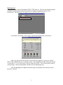
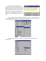
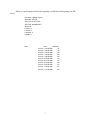
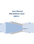
JAMAR TRAX RD
The TRAX RD is an automatic traffic recorder designed and built by JAMAR
Technologies, Inc. Since the unit is a “Raw Data” unit, it records a time stamp of every sensor
hit that occurs during the period of data collection.
This unit works using air switches and road tubes to sense traffic. When a vehicle runs
over the road tube, air moves within the tube towards the unit. This “air shot” enters the unit and
activates the air switches, which allow the unit to detect the passing vehicle.
Detector Package
The system consists of the following:
1) Trax RD box
2) Road Tubes and required installation pieces
3) RS-232 communications cable
Power Requirements
The TRAX RD is powered by a rechargeable lead gel battery. Our unit also included the
optional solar panel. When the unit on is turned on, the display shows the battery voltage during
its startup procedure. JAMAR recommends that the battery is recharged if it displays less than 6
volts. The TRAX RD will automatically shut down when the battery voltage falls to 5 volts, thus
stopping data collection. All the data that was stored by the unit prior to shut down is stored and
can be retrieved.
Installation
Our installation of the TRAX RD used the “mini” road tubes. The tubes must be placed
exactly perpendicular to the flow of traffic. Tube length is very important in order to record
accurate vehicle data. If a “long” tube setup is used, 50 ft. of mini tube should be used. A
combination of “short” tubes and “long” tubes can be used (see page 4-2 of the TRAX RD
User’s Manual for the correct lengths of tubes.)
There are different road tube layouts depending on the study requirements. We used L5
which is for two lanes of traffic moving in the same direction. Our mini tubes (two of them)
were 50 ft. long, 24 ft. across the two lanes of traffic, and 26 feet of extra tube coiled near the
TRAX RD unit. The far end of the tubes was sealed with a plug that was inserted into the tube
and the other end was connected to the TRAX RD unit. To install the tube onto the road, a nail
and looped nylon material were used to secure the plugged end of the tube on the near and far
sides of the road. Sticky tape was placed every 2 ft. or so to secure the tubes to the road so that
they do not oscillate as vehicles pass over them. It is important to not stretch the mini tubes
during installation to ensure proper data collection.
Setting Up The Unit
The setup of the TRAX RD is very simple. Upon turn on it displays several screens with
information on the current status of the unit. This information includes:
1) The version number of the software.
2) The serial number of the unit.
3) The amount of memory available (TRAX RD has 8 MB of memory).
1
After that, the first screen of the setup menus appears. This screen shows the number of
“Counts” stored (recording sessions that have been closed), and the current battery voltage.
There are only two buttons on the unit, “Do” or “Tab”. Here is a simple outline of the listed
screens. In each of them, “Do” confirms an action and “Tab” takes the user to the next screen:
1) Counts and Battery voltage screen (main screen).
2) Memory screen.
3) Time/Date screen. This screen lists the current time (military format) and date that
are programmed in the RD. The time or date must be changed by using the TRAX
Configuration Utility Software.
4) Dead Time screen. This screen allows to set the Dead Time. This setting tells the
RD how long to wait after it receives a sensor hit before it will accept another. The
default setting is 25 milliseconds. Available options for the Dead Time are:
1. 25 ms
2. 40 ms
3. 90 ms
4. 300 ms
5) Layout screen. Press “Do” to cycle through the different road tube layouts (refer to
chapter 5 of the TRAX RD User’s Manual for information about the layouts).
6) Data Module screen. This screen allows users to check the status of the module and
transfer data from the RD for easy transport back to a computer. For more
information on this screen refer to page 2-5 of the TRAX RD User’s Manual.
7) Erase Counts screen. This screen allows to delete all the currently stored counts from
the RD’s memory.
All this setup can be done easily by using the Trax Configuration Utility (TCU). In fact,
some parameters can only be changed using
the TCU, such as Time/Date and Site ID. The
TCU must be installed onto a computer. The
TRAX RD unit is connected to the computer’s
comm port via the supplied RS232
communications cable. Make sure that the RD
is on and not asleep. Open the program and
select a comm port, click “Ok” and the
program will open the screen shown. A
message confirming that the unit was found on
the selected comm port should be shown. The
DBV, Spacing, and Interval Length settings are
not used with the RD and therefore cannot be
edited.
Running The Unit
Upon starting a new count, the Count
Screen is displayed on the RD unit. This screen show the number of sensor hits as they happen
(refer to page 2-6 of the TRAX RD User’s Manual for more information). “Tab” allows to you
view information about the unit, such as the time and date, the battery voltage, the ID screen and
back to the count screen. To end a count, simply turn off the TRAX RD unit.
2
Data Retrieval
The data are retrieved through the TRAX PRO software. The first time that the program
is loaded, user preferences need to be set (these can change at anytime by going to File /
Preferences). The following screen appears once preferences have been set:
Download a Trax Counter button
Click on the “Download a Trax Counter” button which displays the screen below:
Make sure that the TRAX RD unit is connected to the computer’s comm port with the
RS232 cable, and that the unit is on and not asleep. Select Baud Rate and the comm port the unit
is connected to. You can also specify where to send the temp file. After selecting these options,
click on Begin. The bar at the bottom will fill as the download progresses.
After downloading has completed, the following screen appear from which one selects
the file to “Process.”
3
Here you can set your “Processing Options.” After options have been set, click on “Save
and Process.” After the data is processed, the user is presented with the Per Vehicle Menu, as
shown below:
“Interval Length,” “Select Times”, “Count Type” such as Volume, Speed, Axle Class,
etc. are selected as shown below:
4
Pages 4.11 – 4.13 of the TRAX Pro Reference Manual present information about setting
up a report.
Export button produces the data as the unit recorded it. A record of every vehicle hit and
its corresponding data are exported. The user is prompted with the following screen:
The section to the right (Export Parameters) shows what portion of the data will be
exported. To adjust these parameters, exit the export and make adjustments in the Per Vehicle
menu. Export will ask to save the file which can be opened in Microsoft Excel. A sample of this
data is shown below:
Veh. No.
1
2
3
4
5
6
7
8
9
10
11
12
14
16
18
22
23
24
25
26
27
28
29
Date
6/21/02
6/21/02
6/21/02
6/21/02
6/21/02
6/21/02
6/21/02
6/21/02
6/21/02
6/21/02
6/21/02
6/21/02
6/21/02
6/21/02
6/21/02
6/21/02
6/21/02
6/21/02
6/21/02
6/21/02
6/21/02
6/21/02
6/21/02
Time
Lane Axles Spec Class Length Speed Gap Follow Axle 1-2
8:46:23 AM
1
2
2
2
107
31 143
0
107
8:46:39 AM
1
2
2
2
117
26
16 491
117
8:46:41 AM
1
2
2
2
113
26
2
42
113
8:46:44 AM
1
2
2
2
99
31
3
83
99
8:46:45 AM
1
2
2
2
98
31
1
36
98
8:46:48 AM
1
5
25
9
547
34
3
80
118
8:46:53 AM
1
2
4
5
170
31
4
137
170
8:47:01 AM
1
2
2
2
107
35
8
253
107
8:47:11 AM
1
2
2
2
91
26
10 337
91
8:47:14 AM
1
2
2
2
102
25
3
66
102
8:47:34 AM
1
2
2
2
107
23
20 493
107
8:47:35 AM
1
2
4
5
156
29
1
24
156
8:47:54 AM
1
2
1
1
32
28
0
4
32
8:47:57 AM
1
2
2
2
116
45
0
4
116
8:47:59 AM
1
2
1
1
46
17
1
33
46
8:48:08 AM
1
2
2
2
96
16
0
13
96
8:48:09 AM
1
2
2
2
96
21
1
8
96
8:48:23 AM
1
2
2
2
99
31
14 291
99
8:48:45 AM
1
2
2
2
104
37
22 673
104
8:48:55 AM
1
2
2
2
104
33
10 353
104
8:49:03 AM
1
2
3
3
121
44
8
268
121
8:49:21 AM
1
2
2
2
101
39
18 777
101
8:49:49 AM
1
2
3
3
124
14
27 1052
124
5
To view data by volume, speed, etc.,
simply click Process. If the data starting time
does not reflect the interval time, the user will be
prompted with the screen below. Click “Adjust”
which will make the start time correspond to the
interval time. For example, if the detector was
started at 8:53 AM, and the interval time was 15
minutes, this would change the start time to 9:00
AM.
The user should now have the selected data (volume, speed, etc.) in front of him or her.
The TRAX PRO software allows to export data directly into an Excel format. To do so, go to
File, select Export, and click on Excel Spreadsheet, as shown below.
The following screen allows to specify which contents to export by checking the
appropriate box.
6
Below is a small sample of data after exporting it to MS-Excel and opening it in MSExcel.
File Name: Untitled Volume
Start Date: 6/21/02
Start Time: 8:45:00 AM
Site Code: 000000007671
Station ID:
Location 1:
Location 2:
Longitude: 0
Latitude: 0
Date
6/21/02
6/21/02
6/21/02
6/21/02
6/21/02
6/21/02
6/21/02
6/21/02
6/21/02
6/21/02
6/21/02
Time
Channel 1
8:45:00 AM
87
9:00:00 AM
85
9:15:00 AM
123
9:30:00 AM
108
9:45:00 AM
124
10:00:00 AM
112
10:15:00 AM
147
10:30:00 AM
144
10:45:00 AM
171
11:00:00 AM
167
11:15:00 AM
164
7