1
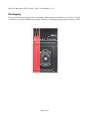
Micro Technologies (NZ) Limited – 406-1 User Manual v1.0.1
MICRO TECHNOLOGIES (NZ) LIMITED
406-1 Personal Beacon Tester
User Manual v1.01
Page 1 of 7
Micro Technologies (NZ) Limited – 406-1 User Manual v1.0.1
Introduction
The Micro Technologies 406-1 beacon tester is a low cost tool that any beacon owner can use to
check that their 406 EPIRB, PLB or ELT rescue beacon is working correctly. The 406-1 tester
provides an independent check of transmitted power, transmitted frequency and that valid data at
the correct rate has been sent from your beacon.
If you require a 406 decoding solution consider the 406-2 decoder or the 406-SD1 storage decoder.
The 406-1 beacon tester is small enough to keep with your beacon (able to fit on a keyring), and
extremely simple to use and understand with single button operation with clear “OK” and power
level indicators.
An annoying aspect of owning a 406MHz rescue beacon has always been that it is very difficult (or
costly) for users to test their beacon. Beacon testers until now have been well out of reach of the
consumer, being many times the cost of the beacon itself. If you could actually afford one, you
needed to be trained in order to understand the parameters that were being tested.
The patent pending 406-1 beacon tester has been developed to be simple to use for ALL beacon
owners. No specialist technical training is required.
Operating Instructions
1. Hold tester vertically 1.5 meters (average adult full arm span) from beacon to be tested.
2. Press button on the 406-1 tester. Red, green and yellow indicators will light as part of a self
check sequence. If all is well the red indicator will begin to flash once a second (for a
maximum of 15 seconds).
3. Within 15 seconds, operate the "test" function on the beacon to be tested. DO NOT TURN
THE BEACON ON!
4. If the beacon test transmission is good, then the red indicator on the tester will stop flashing
and the green and yellow indicators will light.
Indicators:
Immediately after pressing the 406-1 button all indicators will light as part of a self check sequence.
After the self test sequence the indicators when lit have the following meaning.
Green
If the green indicator (marked "OK") lights then all beacons tests have passed (power, frequency
and data).
Red
The red indicator (marked "TEST") lights once per second after the 406-1 tester button is pressed.
This indicates that the tester is currently scanning 406 frequencies (or the user selected frequency)
looking for a valid transmission. The indicator will stop flashing after either detecting a valid 406
transmission, or will stop after 15 seconds (after rapidly flashing to reinforce that the test has
failed).
Page 2 of 7
Micro Technologies (NZ) Limited – 406-1 User Manual v1.0.1
Yellow
The yellow indicators give an indication of signal strength. At least 3 yellow indicators must light
in order to provide a passing result.
Setting the 406 Test Frequency
When not configured, the 406-1 tester scans 406.025MHz, 406.028MHz, 406.037MHz and
406.040MHz - this default configuration will suit most users.
1.
2.
3.
4.
•
•
•
•
•
To change the frequency being tested:
Press the 406-1 button. The indicators will flash as part of the self test sequence. The red indicator
will now begin to flash once per second.
Press the button again and hold without releasing for 5 seconds. After 5 seconds both the red
"TEST" indicator AND green "OK" indicator will light.
The yellow signal strength indicators will show the selected frequency mode.
Release the button, and momentarily press until the desired frequency mode is selected.
Frequency Modes:
No yellow indicators lit - 406.025MHz, 406.028MHz, 406.037MHz and 406.040MHz are all
scanned.
First yellow indicator lit - 406.025MHz only is tested.
Second yellow indicator lit - 406.028MHz only is tested.
Third yellow indicator lit - 406.037MHz only is tested.
Fourth yellow indicator lit - 406.040MHz only is tested.
The selected frequency test mode can be determined each time the 406-1 button is pressed by
examining the indicator flash sequence. The default flash sequence is red, green, yellow 1, yellow 2
through to yellow 5. If a frequency mode has been set, the yellow indicator set for that frequency
mode will light before the red indicator lights. e.g. When the 406.028MHz frequency mode has
been selected, the second yellow indicator will light before the red indicator.
A demonstration video can be found at www.microtechnologies.co.nz
Low Battery Check
•
•
1.
2.
3.
4.
5.
The tester battery is checked during the self test sequence (immediately after the tester button is
pressed). The battery needs replacing when:
No indicators light when the button is pressed or when
All indicators light after the button is pressed, then the red does not continue to flash once per
second.
Replacing the Battery
Using a tool such as a flat bladed screwdriver or small coin, insert tool between case halves and pry
open. The case will snap open when separated.
Remove battery observing polarity of battery (positive is marked on battery clip).
Insert new CR2032 battery and reassemble.
Press the button and test the unit is operational.
If indicators fail to light when button is pressed check battery has been inserted correctly.
Page 3 of 7
Micro Technologies (NZ) Limited – 406-1 User Manual v1.0.1
Technical Information
Signal Strength Indicator
The 406-1 Beacon tester has a 5 level signal strength indicator. When the beacon tester is held
vertically, a full arm span away from the beacon being tested, then all 5 yellow indicators will light
showing that the beacon is transmitting full power (5W or 37dBm). Signal strength indicator moves
in steps of 6dB.
The average full arm-span of an adult when holding the tester, and operating the self test of the
beacon is assumed to be 1.5M.
Since the beacon may not have the aerial released or unfolded, orientation of the beacon may not be
ideal or objects may be in the way, the beacon may radiate its maximum power when tested. To
allow for this the tester will consider any signal strength above 25dBm to be an "OK" pass result.
Although this level for this test is a moderate level below the full beacon transmit power, a 25dBm
transmitter is still considered to be powerful (even for 2 LEDs shown, this power level is higher
than the 121.5MHz homing signal that is also used in the beacon for final location).
The generous pass/fail margin is to simplify testing in conditions that will probably be less than
ideal, and from analysis of beacon failure data, beacon power levels are likely to degrade
significantly in a transmission failure mode, and are less likely to have minor reductions in output
power levels.
Accuracy of the received signal strength by the tester in ideal testing conditions is to within 1dB,
but producing these ideal conditions outside the laboratory is difficult, hence the larger margin
allowed to consider a pass.
Data Tested
Before the green "OK" indicator will light, a data transmission from the beacon must be seen with a
signal strength greater than 25dBm (3 or more yellow indicators). The data changes between
beacons since owner information is included, along with beacon type. The transmission also
changes depending on whether the test button is pressed or the beacon is transmitting a genuine
distress message.
In common with all 406 beacon transmissions is the message bit synchronisation sequence (15 bits
long at 400 bits per second). The presence of this sequence, as a simple test, has been considered
sufficient to establish that data is being transmitted, and at the correct rate. Testing in this fashion
also ensures that if the user uses the tester in an emergency situation (not that this is encouraged) the
tester will also indicate that the genuine data transmission is valid.
Frequency Testing
There are several 406 frequencies used by beacons. By default the 406-1 tester scans:
406.025MHz, 406.028MHz, 406.037MHz and 406.040MHz. If required a specific frequency can
be set by the user (e.g. if testing of 406.028MHz only is desired).
In order for the 406-1 tester to produce a pass result, the beacon must decode data within 5KHz of
the tested 406 frequency, which caters for the 406 beacon specification allowing for a 5 year drift of
5kHz (except 406.028MHz which is +2kHz/-5kHz).
The 406-1 beacon tester is able to determine frequency drift to within 500Hz (at 25 degrees
Page 4 of 7
Micro Technologies (NZ) Limited – 406-1 User Manual v1.0.1
Celsius), but over the temperature range of -10 to +50 degrees Celsius the tester's own frequency
stability results in the acceptance of transmitted signals slightly wider than those in the 406 beacon
specification (an additional 2kHz allowed over full temperature range).
Please contact us if you have tighter frequency testing requirements.
Demonstrations
Demonstration videos can be found on www.microtechnologies.co.nz
Warranty
Micro Technologies (NZ) Limited products are warranted for a period of 12 months after purchase
date against faulty workmanship or materials. Return the product, freight paid by the customer and
the product will be repaired or replaced. Unauthorised work carried out on products will invalidate
the warranty.
Disclaimer
The 406-1 beacon tester does not test all aspects of beacon operation (as with most beacon testers).
Water activation, short term frequency stability, beacon battery condition and 121.5MHz homing
transmitter operation are not assessed.
The 406-1 beacon tester is not waterproof.
IN AN EMERGENCY SITUATION DO NOT DOUBT THAT YOUR BEACON IS
OPERATING CORRECTLY - LEAVE YOUR BEACON SWITCHED ON UNTIL HELP
ARRIVES.
406-1 Customisation
The 406-1 beacon tester has been developed by Micro Technologies (NZ) Limited, and therefore if
a specific requirement exists, customisation of Micro Technologies products may be possible (at
additional cost).
Some changes that may be possible include:
•
More specific packet testing and inspection (checking for a valid test or normal burst
transmission instead of only the framing portion of the packet).
•
Changes to product text and packaging.
•
Much more accurate frequency testing.
•
Power level pass setting (configuring the tester to be used at a much greater distance from
the beacon will yield much more accurate power test results).
Page 5 of 7
Micro Technologies (NZ) Limited – 406-1 User Manual v1.0.1
Packaging
Presented in custom produced blister packaging with backing card suitable for retail sales. Freight
worldwide in waterproof bubble packaging. Thickness including packaging approximately 13mm.
Page 6 of 7
Micro Technologies (NZ) Limited – 406-1 User Manual v1.0.1
Specifications
Frequencies Tested:
406.025MHz, 406.028MHz, 406.037MHz and
406.040MHz
Battery
3.0V CR2032 Coin Cell
Battery Life
Several hundred operations. Without use, the
406-1 has a shelf life without use of several
years.
Environmental Protection
The 406-1 is not waterproof.
Data Tested
Presence of 406 transmission packet preamble at
400bps.
Indicators
Red, Green and Yellow LEDs.
Weight
Approx 20g
Transmit Pass Power level
Approx 25dBm (based on a test distance of
1.5M)
Power Indicator Step Size
6dB per yellow LED.
Page 7 of 7