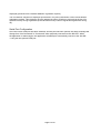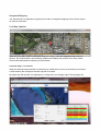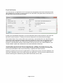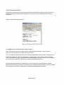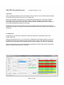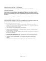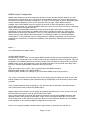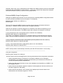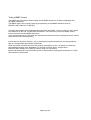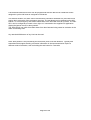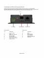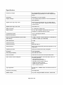
1
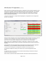
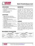
406 Local Emergency Receiver
User Manual
Page 1 of 28
Table of Contents
406-LER Beacon Decoder/Receiver...................................................................................................1
Introduction..........................................................................................................................................3
406 Decoder PC Application (v1.0.2.0)...............................................................................................5
Serial Port Configuration.................................................................................................................6
Integrated Mapping..........................................................................................................................7
Live Map Updates.......................................................................................................................7
External Map Tool Button...........................................................................................................7
Email Notification............................................................................................................................9
Testing Email Notification........................................................................................................10
PC Application Accepted Serial Data Format................................................................................10
Licensing........................................................................................................................................11
Location of Application Modified Files.........................................................................................12
406-LER Decoder/Receiver (firmware revision v1.19)....................................................................14
Operation.......................................................................................................................................14
Configuration.................................................................................................................................14
Adding Entries to the Hex 15 ID Database....................................................................................16
NMEA Output Configuration........................................................................................................17
Preferred NMEA Output Configuration........................................................................................18
Testing NMEA Output...................................................................................................................19
Modulation Digital Input...............................................................................................................20
Serial Out Packet Format...............................................................................................................20
Checksum Calculation...................................................................................................................22
Periodic Message...........................................................................................................................22
406 Selective Decode.........................................................................................................................23
406 Selective Decode Applications...............................................................................................23
Installation..........................................................................................................................................25
Connecting to the 406-LER..........................................................................................................26
406-LER Customisation....................................................................................................................27
Disclaimer...........................................................................................................................................27
Specification.......................................................................................................................................28
Page 2 of 28
Introduction
The 406-LER is a 406 beacon decoder/receiver that can operate autonomously or when connected
directly to the supporting 406 Decoder PC application.
The 406-LER has a non-volatile in-built message logging capability, allowing the last 500,000
decoded 406 messages to be stored and retrieved when connected to a Windows XP or Windows 7
PC computer. An on-board relay can be configured to close on reception of a valid 406 message.
Decoded and stored messages are immediately sent as an RS232 message that contains the beacon
hex 15 ID, position of the beacon (if provided), and signal strength.
A digital input can be configured to accept raw data from an existing receiver if required.
When connected to the 406 Decoder application, email notifications can be provided when
messages are received or communication to the 406-LER has been lost.
A user configurable NMEA 0183 sentence can be enabled to allow decoded beacon positions to be
fed into a NMEA capable device such as a chart plotter.
The 406-LER features a high sensitivity, low current receiver, that makes it well suited for remote
solar and battery powered installations.
The 406-LER can be used to:
•
Provide an alert when a 406 message has been received by configuring the on-board relay.
The relay could be used to apply power to serial capable transmitter to forward the message.
•
Connect directly to an existing receiver raw data source, simplifying installation in some
cases.
•
Provide beacon encoding details, including signal strength for testing at point of sale or after
reprogramming.
•
Remotely monitor areas for 406 beacon activity that may have poor satellite coverage, such
as canyons or mountainous regions.
•
Determine beacon parameters and GPS position.
•
Display a 406 beacon location through a NMEA sentence to navigation equipment.
•
Provide early immediate emergency notification (since there can be a delay in some cases of
up to 2 hours before a 406 message is passed on to the satellite downlink station).
•
Connect to a vehicle for instant mobile alert and location monitoring.
•
Using the patent pending “406 Selective Decode” feature:
◦ Produce a highly effective “Man Overboard Alert”
◦ Produce a diver resurfacing notification for dive boats.
◦ Produce a shore based yacht club distress monitor.
Each one of the “Selective Decode” solutions allow notification to be received and provide
Page 3 of 28
an alert when either the “Test” button is pressed or a full alarm is produced, without false
alarms from beacon testing and alarms in the wider surrounding area.
The 406-LER can be connected and monitored by:
•
Connection to the on-board relay.
•
Connection to the RS232 port to a forwarding transmitter.
•
Connection via the internet through a low cost third-party serial to Ethernet converter.
•
Direct or remote connection to the supporting 406 Decoder PC application.
•
Automatic email notification.
•
Connection via a 4800 baud serial link to NMEA 0183 compatible navigation equipment.
A periodic message can be configured to send a test message to help determine system health.
Page 4 of 28
406 Decoder PC Application (v1.0.2.0)
When connected to the supporting 406 Decoder PC application, remote real-time notification of 406
transmissions is possible, decoding and displaying all beacon protocol parameters. Time-stamped
messages are additionally stored on the PC that is integrated with Google Maps to display the
location of the alert when provided. The 406 Decoder application, provides visual and audible
alerts of 406 distress transmissions.
Through the configuration of a simple external language file, the application can be configured to
operate in any language.
Distress and test messages can be clearly differentiated. Distress messages are marked in red, test
messages in green. Messages retrieved from the 406-LER on-board storage are displayed in
yellow. New, incoming distress messages provide an audible alert until acknowledged.
When a history entry is highlighted that contains a valid position, a “Map View” button is visible
that when pressed, shows the location of the beacon transmission (when an internet connection is
available).
Coma separated results are logged directly to file (results.csv) located in the common application
data directory. e.g. on a windows XP machine the results.csv file could be found in:
C:\Documents and Settings\All Users\Application Data\MicroTechnologies\406 SD-1
All information available in the history list is written to file, and time-stamped with the time
written.
On application start-up the results.csv file is loaded to allow browsing of entries and viewing of
historical entry beacon parameters.
When a beacon certificate number has been decoded, the beacon model and manufacturer is
Page 5 of 28
displayed (produced from COSPAS-SARSAT registration reports).
The new beacon checksum is displayed (introduced in July 2012) that allows a more robust beacon
registration method. This checksum is being adopted by some countries to ensure that the hex id is
entered correctly during registration (there have been many cases of registration against the wrong
ID).
Serial Port Configuration
Once the correct COM port has been selected, and the port has been opened, the status message will
change from “Not Connected” to “Connected” when physically connected to the 406-LER. When
the application is started again, the application will attempt to automatically connect to the 406-SD1 using the last opened COM port.
Page 6 of 28
Integrated Mapping
The 406 Decoder PC application supports two modes of integrated mapping, both of which require
an internet connection.
Live Map Updates
When the “Live Map” option is selected through the “config” menu the integrated map window is
opened. This map window is automatically updated and displays the position of the most recent
received 406 transmission containing a valid location.
External Map Tool Button
When the external map tool button is pressed (only visible when an entry in the history list contains
a valid location) the configured external map tool is invoked.
By default the 406 Decoder PC application is configured to use Google maps. The language.xml
Page 7 of 28
file that provides access to all application messages also contains control over the mapping interface
through the <MapTool> tag. Altering the contents of this tag can allow the application to use
another tool, or modify the behaviour of the configured mapping tool.
Page 8 of 28
Email Notification
The 406 Decoder PC application can be configured to automatically send email notifications when
406 messages are received or communication to the 406-LER is lost (either direct connection or if
the 406-LER is being monitored remotely).
Emailing can be disabled completely or provide notification when communications to the 406-LER
has been lost and restored . Filtering can also be configured to not send self test messages.
The Periodic Reset Time is most useful when monitoring a remote 406-LER. The 406-LER can be
configured to send a periodic message. When this message is received the PC application sets a
timer to the Periodic Reset Time. If this timer is allowed to count down to 0, the application will
provide a visual indication that the communication link has been lost. If the “Alerts Enabled”, and
“Comms Status” options are selected, then an email notification will be sent.
The Min RSSI Level should normally be configured to be -130dBm. A low value (such as -130)
means that all packets of even a very low signal strength are logged and emailed. Increasing the
level may be preferable if there is an interest only in signals from closer beacons.
Obtaining a gmail account for the PC application is a simple way to send out email messages, and
also keep a separate record of all emails sent by the application. The host and port settings shown
will work well for gmail. Alternatively other SMTP email hosts can be used.
Page 9 of 28
Testing Email Notification
Pressing the small button in the bottom right hand side of the bottom status bar generates a test
distress message for demonstration purposes and confirming that email settings are correctly
configured.
Typical email notifications appear as:
PC Application Accepted Serial Data Format
When connected to the 406-LER the 406-SD- presents RS232 9600:N:8:1 data in the MT1...
format as fully described in the “Packet Format” section.
e.g. MT1001095TLC009028155C319131412233N0645536WB47C (followed by a carriage return)
Data when presented in this form has already undergone BCH error correction, and is provided
from the 406-LER only when the packet has been successfully corrected. Up to incorrect 5 bits can
be corrected using the BCH correcting code used by the 406 transmission.
Connecting the 406 Decoder PC Application to a terminal program and sending this example
packets provides a simple method to test the serial PC interface. Default packets are also available
in the results.csv file when the application is installed for demonstration purposes.
Page 10 of 28
Licensing
The 406 Decoder PC application is free for a single user to install with the purchase of the 406-SD1. The application is tied to the PC that application is to installed onto. When the application is run
without a valid license the PC Hardware ID is displayed:
To Unlock the Application:
1. Enter the 20 character key that was supplied when the 406-LER was purchased. All keys
entered must be upper case with a hyphen separating each block of 5 characters.
2. If a valid product key has been entered the “Generate Email” button will be enabled.
Clicking on this button will invoke your PC default email application to build a default
“request for activation key” email.
3. Send this email. Sending this automatically produced email is the most reliable method to
obtain an activation key since the chance of supplying an incorrect hardware ID is reduced.
4. After the email has been processed (this may take up to 24 hours) an activation key will be
returned unlocking the application for use on the PC with the specified hardware ID.
5. Enter the supplied activation key.
6. Press the “Activate” button. If the activation key matches the hardware ID and product key
then the application will launch.
This process will not need to be repeated, even when upgrading the PC application. If the unlock
process fails then email either a screen-shot of the license activation screen with your product key to
[email protected]
Page 11 of 28
Location of Application Modified Files
All files that are modified by the 406 Decoder PC application are stored in the local application data
directory.
These files are:
results.csv (all beacon decoded data)
config.xml (all application and 406-LER settings).
These files are ALSO located in the application directory, but are only used as default files for when
the application is run for the first time. Changes to these files in the application directory will have
no affect.
When the PC application is upgraded, the configuration and results files in the location shown
below will not be overwritten.
On a Windows XP PC:
C:\Documents and Settings\All Users\Application Data\MicroTechnologies\406 SD-1
On a Windows 7 PC:
You will first need to make sure these folders are not hidden.
1. Start->Control Panel->Appearance and Personalisation->Folder Options.
2. Click View
3. Advanced Settings->Show hidden Files, folders and drives.
The path to the common application data can be found by entering:
%ProgramData% path into Windows File Explorer.
Page 12 of 28
Files that are not modified by the application are stored in the application directory, such as:
Langstrings.xml
CountryStrings.xml
Page 13 of 28
406-LER Decoder/Receiver
(firmware revision v1.19)
Operation
When operating normally the green LED flashes once per second. The red LED flashes erratically
as data is presented from the receiver or the digital input.
After a 406 message is received (test or normal distress burst) BCH error correction is applied
(correcting up to 5 incorrect bits) and if the packet is valid the message is then written to the
internal SD card and sent out the serial port. Limited queuing functionality allows the reception of
a new 406 message while another is processed.
Depending on how the relay is configured, the relay will close when a valid packet is processed. If
the periodic message is configured, a message as described below will be sent out the serial port as
configured.
Configuration
Configuration of the 406-LER is performed via the 406 Decoder PC application (menu item
Config->406-LER).
Settings can loaded from the “File” menu option, changed and saved again without connection to
the 406-LER. Writing these settings (by pressing the “Write” button) to the 406-LER can only be
performed when connected to the hardware (and the status message “Connected” is displayed).
Settings can be read directly from the 406-LER by pressing the “Read” button (when connected)
and then modified and saved to file if required.
Page 14 of 28
406-LER Config Items:
General->Serial:
A serial number from 0-999 that identifies all packets transmitted from the 406-LER.
General->Source:
RX (406 data decoded from internal receiver) or Input (406 data decoded from the digital input).
General->Periodic:
Time in seconds between periodic “heart-beat” packets (0-32000). Setting to 0 disables the periodic
message.
Relay->Mode:
“All” (Relay closure on all 406 decodes), “No Test” (Relay does not close when test packets are
received) and “Db Only” (relay will only close when a hex Id matches one of the hex Ids
programmed into the Hex 15 Id database).
Relay->Close Time:
The period that the relay will close for when configured to do so.
Hex I5 Id DB:
The list of up to 50 beacon hex 15 codes that can be programmed. This database will be used to
control the relay ONLY when Relay->Mode is set to “Db Only”. In this mode the relay will only
close when a decoded 406 packet matches the hex 15 Id in the database. If the hex 15 code
contains position information (as is the case for some 406 protocols) then the position information
is masked during the match process to ensure activation of both “test” and distress transmissions.
NOTE: Regardless of configuration, all 406 decoded messages are logged and displayed in the
“History” list box. The relay and database configuration only provides selective control over relay
operation.
NMEA Mode:
Configures the NMEA output mode of operation – see NMEA Configuration. If not using NMEA
output sentences, ensure the NMEA mode is set to “---”.
Page 15 of 28
Adding Entries to the Hex 15 ID Database
There are two methods that can be used to add entries to the Hex 15 Id database:
Using the PC Application:
The beacon hex ID can be copied from the beacon hex ID history list, manually entered or the
config.xml file can be read, modified, then loaded into the 406-LER. The config.xml file can be
found in the local application data directory. On a Windows XP machine the results.csv file could
be found in:
C:\Documents and Settings\All Users\Application Data\MicroTechnologies\406 SD-1
Automatic “learning” of beacon hex ID codes:
Using this method a connection to a PC is not required. This method would be convenient if the
406-LER was used in an application such as a “Man Overboard” monitor.
To automatically learn beacon hex Id codes:
1. Ensure that the 406-LER is configured to operate in the “Selective Decode” mode of
operation. This will only need to be checked and configured once. By default the 406-LER
is configured to decode all 406 messages.
2. Turn the 406-LER off by pulling out the power connector.
3. Restore power to the 406-LER by re-inserting the power connector. The green LED will
now flash rapidly for 10 seconds.
4. While the 406-LER green LED is flashing rapidly, press the “Test” button on the beacon to
be added to the database.
5. If there are 50 or less beacon Ids in the database, and the 406 message was decoded
successfully, then the relay will close.
6. The green LED will now flash slowly, indicating that the 406-LER is now operating
normally.
7. The system can be tested at any time by pressing the “test” button on the beacon.
Page 16 of 28
NMEA Output Configuration
NMEA 0183 sentences can be configured to be sent from the decoder with the position of a 406
transmission if configured to do so. As soon as the first NMEA sentence is sent out the serial port
the serial output rate is changed to 4800:N:8:1. In order to connect again to the PC application (that
communicates at 9600:N:8:1) turn off the 406-LER, then on again. When NMEA output is
enabled, there is NO NMEA output for the first 10 seconds of 406-LER operation. After the 10
second start up period, the configured NMEA sentence is sent out once every second (if a message
with a valid position has been received).
Valid position encoded NMEA sentences will be provided by ANY 406 location transmission.
Depending on the configuration, the NMEA output will be updated for either any valid location
transmission (including any 406 beacon “Test”), or only transmissions with matching database
entries plus any other distress 406 transmission. Full details provided in the “Preferred NMEA
Configuration”. In the preferred mode of configuration an updated map position can be provided
separately for each beacon in the beacon database, plus separately marked distress and test
locations.
Mode '---':
This mode disables all NMEA output.
All Other NMEA Modes:
Other modes, such as “WPL” provide typical NMEA sentences that may be accepted by navigation
equipment. The sentences for any of these modes can be modified and stored if required. Tags can
be added into the NMEA sentence to add the position of the 406 beacon transmission. All of these
NMEA modes can be programmed by to be ANY NMEA sentence, but provided in the drop down
list only to indicate typical NMEA sentences that may be used.
e.g.
When the mode is set to “WPL”, this is a typical way-point NMEA sentence.
$GPWPL,[4807.038,N,01131.000,E],MOB* or
$GPWPL,[4807.038,N,01131.000,E],#* (see “Preferred NMEA Output Configuration”)
The '[' and ']' characters are not actually sent, but are simply used as markers to allow a “real” 406
beacon position to be added in place automatically by the 406-LER over the dummy location data
provided.
In any of these NMEA modes of operation, if the 406-LER has not decoded a 406 transmission
with a valid position there will be NO NMEA output.
NMEA output can be tested in a real system by pressing and holding the “TEST” button on a GPS
PLB with GPS test support, such as a ACR RescueLink PLB.
Once a valid message is received with position information, the configured NMEA sentence with
updated position and checksum information is sent out the serial port at 4800:N:8:1 once every
second until power to the 406-LER is removed. Be sure to check that the beacon ID is first added
to the database, or the preferred NMEA configuration is being used.
NOTE: Any configured NMEA sentence MUST begin with a '$' character and end with a '*'
Page 17 of 28
character. Also if the '[' and ']' characters are not added to the NMEA sentence then NO DISTRESS
POSITION WILL BE ADDED TO THE OUTPUT – make sure a system has always been deployed
with these characters in place as shown in the example above.
Preferred NMEA Output Configuration
Although any NMEA output sentence can be configured, the following NMEA configuration should
be used if possible (available only from firmware v1.19 onwards).
$GPWPL,[4807.038,N,01131.000,E],#* or
$GPWPL,[],#*
The use of the waypoint NMEA sentence as shown above with the '#' character before the
terminating '*' character allows a special mode of waypoint operation.
When the '#' character is used the waypoint ID is rewritten by the 406-LER depending on the
nature of the 406 transmission. The NMEA output when using the '#' character is as follows:
For any transmission with a valid position (that is matched in the database)
$GPWPL,4807.038,N,01131.000,E,MOB-1*
The match in the database is displayed as a separate waypoint. Output waypoints will be from
MOB-1 through to MOB-50 depending on the location of the beacon ID in the beacon database.
For any “Distress” transmission with a valid position (from any beacon not in the database)
$GPWPL,4807.038,N,01131.000,E,406-SOS*
For any “Test” transmission with a valid position (that is not in the database)
$GPWPL,4807.038,N,01131.000,E,TEST*
NOTE: Actual position is automatically inserted by the 406-LER and shown in red for clarity.
Using the configuration:
$GPWPL,[4807.038,N,01131.000,E],#*
as shown above has the advantages when receiving transmissions with valid position information:
1. Allows separate tracking of all beacons in the beacon database can be managed
simultaneously. On navigation equipment this will allow up to 50 beacons to be shown, all
of which will update position independently.
2. Allows the 406 beacon that has an entry in the database to be identified (e.g “MOB-21”) on
the navigation device.
3. Allow unknown 406 beacon “distress” locations to be displayed (all unknown beacons use
the same waypoint of “406-SOS”).
4. Allow unknown 406 beacon “test” location to be displayed (all unknown beacon test
transmissions use the same waypoint of “TEST”)
Page 18 of 28
Testing NMEA Output
The NMEA test functionality allows testing various NMEA sentences for best compatibility with
navigation equipment.
The NMEA output can be easily tested by programming a valid NMEA sentence such as:
$GPWPL,4807.038,N,01131.000,E,#*
A suitable test latitude and longitude position should be embedded. You do not have to worry about
the checksum on the end, the 406-LER will add this. There are many sources available via the
internet that fully describe NMEA sentences.
Once programmed into the 406-LER, the test sentence will be sent out the serial port once a second
(after the 10 second startup period).
Ensure that you DO NOT add the '[' and ']' characters during the test process, this will guarantee
that your programmed test position will be used.
When the system has been proven to be working, then add the '[' and ']' characters, to allow the
actual distress position to be embedded. For the test sentence above, change this to:
$GPWPL,[4807.038,N,01131.000,E],#* before using in a real system.
Before final deployment ensure that the system is fully tested by pressing the test button on a PLB
that embeds a valid position.
Page 19 of 28
Modulation Digital Input
The digital input can be used to present raw data to the decoder that can be used instead of the
internal receiver. This may be useful if there is an existing receiver that is capable of decoding PSK
data that is transmitted by 406 beacons. By default support for this feature is not provided from
firmware revision 1.17 onwards. If this is a requirement, please contact
[email protected]. For full details on the use of the modulation digital input see
application note AN002 “Modulation Digital Input Support”.
Serial Out Packet Format
Data provided from the 406-LER(9600:N:8:1, no hardware handshaking) is in the following
format:
MT1UUUNNNTFHHHHHHHHHHHHHHHSS112233N4445566WYYYY
Where:
MT1 is fixed and actually “MT1” or “SD1” if the serial output is a result of using the SD access
commands.
UUU- is a 3 character 406-LER configurable ID
NNN -is a 3 decimal digit cycling packet sequence number from 000 to 511. This sequence number
increments after each new test of distress message is received. After 511 the sequence cycles to 000
and begins again.
T – is a single character message type 'T' or 'A' (test or distress alert)
F – is a single character format flag 'S' or 'L' (short or long)
HHHHHHHHHHHHHHH – is a 15 character hex code used to define beacon owner and beacon
capabilities as per the 406 beacon specification.
SS – is a 2 character signal strength indication – “00” if not used.
11 – is a 2 decimal character latitude degrees
22 – is a 2 decimal character latitude minutes
33 – is a 2 decimal character latitude seconds
N – is 'N' or 'S'
444 – is a 3 decimal character longitude degrees
22 – is a 2 decimal character longitude minutes
55 – is a 2 decimal character longitude seconds
W– is 'W' or 'E'
YYYY – is a 4 character checksum (calculated from M)
Page 20 of 28
If location characters are all '*' then this is a default position. If all location characters are '-' then
there is no location information available.
Legitimate example packet:
MT1001095TLC009028155C319131412233N0645536WB47C
Page 21 of 28
Checksum Calculation
The 4 character rolling left checksum, starting at the 'M' is calculated as follows:
short calculateChecksum(short packetLen, char* dataSource)
{
short checksum;
short i;
checksum = 0;
for (i = 0; i < packetLen; i++) {
checksum ^= dataSource[i];
/* Roll left
if (checksum
checksum
} else {
checksum
}
}
*/
& 0x8000) {
= (checksum << 1) | 0x01;
<<= 1;
return checksum;
}
Periodic Message
The period message can be used to confirm that the 406-LER is operational once installed in a
remote location.
When the period timer expires, the following message is sent out the serial port:
MT8UUUNNN
Where:
MT8 is fixed and actually “MT8”. commands.
UUU- is a 3 character 406-LER configurable ID (Serial number)
NNN -is a 3 decimal digit cycling packet sequence number from 000 to 511. This sequence number
increments after each new test of distress message is received.
The period message does not contain a checksum since the repeating pattern is predictable.
Page 22 of 28
406 Selective Decode
The Micro Technologies' patent pending selective decode feature allows a database to be built of
beacon hex ID codes within the decoder (up to 50 different 406 beacons of any type).
This means that the decoder will only activate the alert output when a 406 transmission has been
received by beacons with the matching unique ID.
Using this technology, new systems can be developed using powerful 406 beacons to instantly
provide an distress alert, using the test button or fully activating the beacon. In many cases
immediate assistance can be provided without the need to notify search and rescue.
These systems are secure, and will not result in a false activation from beacons being tested or that
have been activated in the wider surrounding area.
406 Selective Decode Applications
Man-Overboard Alarm
The 406-LER is perfectly suited as the foundation of a marine 406 man overboard system,
providing an instant alert, with very high range capability.
A vessel for example may have 20 crew, all with PLB devices fitted to life jackets. Each of the PLB
hex codes can be programmed into the 406-LER decoder. This means that the decoder on a vessel
can be alerted by the press of the test button from any of the crew members, or by full activation of
the beacon. The 406-LER will not produce any false alarms from other beacons in the wider
surrounding area.
A PLB has a much higher power output than most other man overboard systems, so can have a
higher range from the vessel. PLBs are also becoming increasingly more affordable, and are now a
similar price to traditional Man-Overboard transmitters. The decoder when used for this application
can still provide position information to crew members on the vessel, that can then be processed by
a connected mapping tool. All activations would be logged normally.
Diver Resurfacing Alert
The 406-LER is well suited to provide a diver resurfacing alert. A resurfacing diver, if carrying a
PLB, can in distress press the test button on a beacon and signal for assistance from the dive boat
with or without notifying the emergency services.
There is no chance of false alerts from beacons being tested or activated in the wider surrounding
area, messages are all logged and notification is instant. If a beacon is fully activated, the position
can be provided by the decoder allowing early diver location in an emergency situation.
Yacht Club Distress Monitor
Page 23 of 28
A shore based 406-LER receiver can be programmed with the 406 PLB or EPIRB hex codes
assigned to yacht club boats or assigned to individuals.
In a distress situation, an alarm can be raised before a situation escalates to a point that would
require the involvement of the emergency services. The test button can be pressed on the 406
beacon, or a full emergency alert raised. Notification to the 406-LER receiver is instant. The 406SD-1 can be configured to control a siren, light or if connected to the supplied PC application
display the beacon hex ID or alert position.
The 406-LER will not suffer from false alerts from other beacons being tested or activation in the
wider surrounding area.
Any standard 406 beacon of any kind can be used.
Note: Alert position is not provided by the test button press of all 406 beacons. Typically 406
transmitters that support sending of location information in the test transmission require a
different mode of activation, such as holding the test button for 5 seconds.
Page 24 of 28
Installation
The 406-LER should be situated away from direct sunlight, extreme vibration and heat sources, and
high power transmission sources.
An external aerial correctly manufactured to operate at 406MHz will result in best performance. Do
not situate the aerial immediately next to the aerial of a high power transmission source.
Maximum tolerated input power into the decoder BNC connector is 17dBm. Connecting directly to
a 406 beacon will result in certain damage. Signal strength measurements are accurate to within
0.5dB, but are relative and not calibrated. Power strength recording can be performed by using a
reference beacon and comparing results against the tested or calibrated reference.
Page 25 of 28
Connecting to the 406-Local Emergency Receiver
Looking at the end of the 406-LER without the BNC connector, there is a 2 terminal power
connector situated to the left, a 8 pin RJ45 connector in the centre and a 6 pin RJ12 connector to the
right. Direct PC RS232 connection possible with optional 12-45 serial adaptor cable.
Pin 1
12 V Supply
Inputs/Outputs
Inputs/Outputs
RS232 In/Out
RS232 In/Out
Pin
Description
Pin
Description
1
2
3
4
5
6
7
8
Do not connect
GND
Digital Raw Data input
Do not connect
Do not connect
Relay Normally Open
Relay Normally Closed
Relay Common
1
2
3
4
5
6
GND
Do not connect
Do not connect
Do not connect
RS232 Tx/NMEA Out
RS232 Rx
Page 26 of 28
406-LER Customization
The 406-LER Storage decoder has been developed by Micro Technologies (NZ) Limited, and
therefore if a specific requirement exists, customization of Micro Technologies products may be
possible (at additional cost).
Some changes that may be possible include:
– Changes to labeling.
– Specific language support for PC application.
– Support for specific output serial protocols.
Disclaimer
THE REPONSIBILITY LIES COMPLETELY ON THE USER TO ENSURE THAT THIS
DEVICE IS TESTED, THROUGH METHODS THAT ARE APPROPRIATE, TO CONFIRM
THAT ALL SYSTEM COMPONENTS (THAT THIS DEVICE AND PC SOFTWARE MAY BE
PART OF) ARE WORKING CORRECTLY.
THIS DEVICE AND SOFTWARE ARE NOT INTENDED TO BE USED AS A PRIMARY LIFE
SAVING TOOL, BUT MAY BE USED TO COMPLEMENT OTHER EMERGENCY
DETECTION TOOLS ONLY WHEN CORRECTLY CONFIGURED AND TESTED.
THE PRIMARY LIFESAVING MECHANISM FOR 406 BEACONS SHOULD ALWAYS BE
CONSIDERED TO BE THE 406 SATELLITE NETWORK, FOR WHICH THE 406 BEACON
HAS BEEN DEVELOPED.
Page 27 of 28
Specification
Frequency Range
All used 406 Beacon frequencies 406.020MHz –
406.040MHz (upgradable) over entire temperature
range.
Enclosure
Aluminium 77 x 101 x 30mm
Supply Voltage
5-17V without relay operation. 10-17V required for
relay operation.
Digital Input Logic High Level
Disconnected (internal pull up), or voltage above
3.3V. Typical high level 5V. Absolute short duration
maximum 50V.
Digital Input Logic Low Level
Less than 0.3V.
Relay Contacts
1A . Maximum voltage 24V.
Relay Closure
On any 406 message, distress burst only or on
reception of a specific beacon hex ID.
Temperature Limits
-30 to + 85 degrees Celsius.
Receiver Sensitivity
-122 dBm.
Receiver Absolute Maximum Input Power
+17dBm. Do NOT connect directly to a 406 beacon.
RSSI Range
-130dBm to 0dBm (not calibrated)
RSSI Resolution
0.5 dB
Aerial Connector
BNC
Serial Connection
9600 baud N:8:1.
Serial Protocol
Micro Technologies MT protocol as specified, or by
negotiation.
Operating Current
30mA plus 18mA when relay energised.
Firmware
Field upgradable.
SD Storage Capacity
Last 500,000 entries
Error Correction
Correction of up to 5 bit errors per 406 packet.
406 Location Protocol Support
All COSPAS SARSAT C/S T001 Issue 3 Rev 12
Location protocols.
- User Location Protocol
- Standard Location Protocol
- Standard Test Location Protocol
- National Location Protocol
- National Test Location Protocol
- RSL Location Protocol
Type approvals
EN 300 224 , AS/NZS 4769, FCC Part 90 and FCC
part 15
Frequency Recording
Not Supported.
NMEA Output
Any user configured NMEA sentence, 4800 baud.
Page 28 of 28