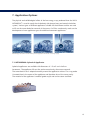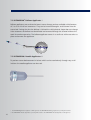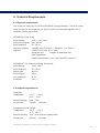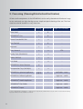
1
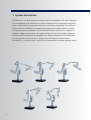
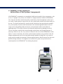
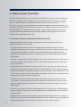
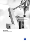
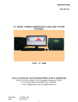
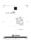
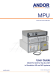
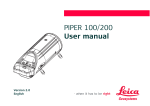
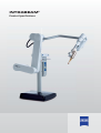
INTRABEAM®
Product Specifications
Content
1.
2.
3.
4.
5.
6.
7.
8.
9.
System Description......................................................................................
Mobility of the System & Interaction of the System Components.................
Dimensions of the System Components ......................................................
X-ray Source and Beam Characteristics ........................................................
Dosimetry System .......................................................................................
Safety Concept (Interlocks)..........................................................................
Application Options ....................................................................................
Technical Requirements...............................................................................
Processing (Cleaning/Disinfection/Sterilization) ...........................................
Page
Page
Page
Page
Page
Page
Page
Page
Page
4
5
6
8
10
12
15
17
18
1. System Description
INTRABEAM® is a mobile radiation instrument which received both FDA and CE approval
for the irradiation of all solid tumors in 1999. Treatment can be performed in operating
rooms, special radiation protection measures are normally not required. The mobile radiation source of INTRABEAM® produces low-energy x-ray radiation which is emitted
isotropically (equally distributed). The INTRABEAM® carrier system with six degrees of
freedom, weight compensation and magnetic brakes ensures easy, flexible and precise
positioning of the source into the targeted area. Ideally integrated in the INTRABEAM®
Cart, the control unit ensures exact setting and monitoring of the desired dose.
INTRABEAM® is a mobile system, which can be used parallel in multiple operating rooms.
4
2. Mobility of the System &
Interaction of the System Components
All INTRABEAM® components are completely flexible and movable. Most components, such
as the 1.6 kg light x-ray source, are stored in a storage container inside the INTRABEAM®
Cart. The cart and floor stand can be easily stowed away with all components when not in
use. With its open space on top of the cart, the system quality check can be done easily on
the cart. The touch pad terminal, control console, dosimeter and everything else needed
for system quality assurance and the treatment are mounted ergonomically on the cart.
Large casters and guiding rollers ensure easy transportation inside and outside the
operating room. The set up of the cart also ensures quick and easy cleaning in the OR.
The cart and floor stand can be moved through normal doors and through elevators if
necessary. When in use, the x-ray source is inserted in the arm of the INTRABEAM® carrier.
With 12 casters in the base, the carrier can be moved smoothly to any position in the OR.
Weight compensation and six axes provide enough freedom to bring the x-ray source in
every position needed for treatment. Electromagnetic brakes hold the source into the exact
position during treatment. The operator can control the system at any time from the
control panel at the INTRABEAM® Cart during the process.
5
3. Dimensions of the System Components
INTRABEAM® X-Ray Source 4
Weight:
1.6 kg / 3.57 lbs
Dimensions:
70 x 175 x 110 mm (width x height x length)
INTRABEAM® Cart
Weight of cart unloaded, incl. permanently mounted
user terminal:
approx. 105 kg / 231 lbs
Payload max.
95 kg / 209.43 lbs
Dimensions:
900 x 1690 x 600 mm / 35.43” x 66.53 “ x 23.62“
INTRABEAM® Floor Stand
Weight:
Transport Position:
275 kg /606 lbs
740 x 1940 x 1500 mm / 29.13” x 76.38” x 59.06”
Consumables:
INTRABEAM® Radiation Shield Flat 20 cm x 20 cm
(10 per box)
Material: Tungsten
INTRABEAM® Drapes
(5 per box)
6
1
13
00
mm
(51
-1
.18
60
“0m
62
m
.99
“)
2
1850 mm 1800 mm
(72.83“ 70.87“)
15
00
mm
(59
.06
“)
ca. 1000 mm
(ca. 39.37“)
1940 mm
76.38“
85
0
mm
(33
.46
“)
m
0m
74
“)
.13
(29
Floor stand
Dimensional drawings
1 Working position (example)
2 Transport position
7
4. X-ray Source and Beam Characteristics
The mobile radiation source of INTRABEAM® accelerates electrons through the
100 mm drift tube with a maximum voltage of 50 kV onto a gold target where the
low-energy x-ray radiation is generated and then emitted isotropically.
4.1 Beam energies
40 kV / 10, 20 or 40 μA
50 kV / 5, 10, 20 or 40 μA
INTRABEAM®
Radiation source
Spher
Spherical
dose distribution
of the x-rays. The steep drop
in the dosage ensures that
most of the radiation remains
in the targeted tissue.
8
4.2 Beam characteristics
Diameter of the
target area [mm]
Approx. Radiation intensity
in the periphery [Gy/Minute]
Approx. Treatment time @
15 Gy [Minute]
10
9.8
1.5
20
2.3
6.5
30
0.9
16.7
40
0.4
37.5
50
0.25
60
All displayed values are valid for the operation of the XRS4 at 50 kV and 40 μA
4.3 Beam allocation
- Point-source type emission
- Dose isotropic around XRS 4 isocenter
- Sharp dose fall off (approx. 1/r3) in soft tissue or equivalent
- Positional uncertainty of delivered dose less
± 1 mm at 40 mm treatment diameter.
4.4 On-site dose monitoring
An internal radiation monitor (IRM) detects the back bouncing counts and assures on-site
monitoring. The IRM result is displayed on the treatment screen of the control terminal so
that the operator knows which dose is being delivered at any time during treatment.
Internal
Radiation
Monitor
Cathode
Gun
Accelerator
Section
Beam
Deflector
Electron
Beam
Gold
Target
9
5. Dosimetry System
A full set of quality assurance and dosimetry tools are provided with the INTRABEAM®. The factory-calibrated system
is delivered with the specific depth dose curves and a reference measurement with the ion chamber belonging to the
system. Every day, a two-step quality control check ensures
that all parameters such as isotropy, internal radiation monitor
and output work do not exceed the tolerances defined during
calibration. For commissioning, a completely shielded, manual
adjustable water phantom can be used to remeasure the depth
dose curve.
5.1 Consignment Sale
(System calibration by Carl Zeiss and with the water phantom)
A water phantom with a highly precise movement technique enables the physicist to position
the tip of the XRS4 exactly above or beside the ion chambers inside the water. Accurate positioning and stepping of the source ensures the remeasurement of the depth dose curve. Even
the measurement of a depth dose curve is possible.
5.2 QA Check (QA Tools)
Inside the so called PDA, five diodes in each direction measure the radiation of the XRS4.
The objective of this test is to ensure the sphericity of the beam. With the PAICH the output
in the z-axis can be checked. An ion chamber is mounted in the probe adjuster in a way that
the ion chamber window is right above the tip of the XRS4. In this test, the internal radiation
monitor and the output are checked.
10
5.3 Online control (IRM)
Prior to each treatment session, the x-ray source must be subjected to a verification
process comprising at least two levels before it is enabled by the software for radiation
emission.
ō9HULğFDWLRQRIWKHLVRWURS\RIWKHUDGLDWLRQğHOG$SKRWRGLRGHDUUD\3'$LVXVHG
to test the radiation field in all 5 axes. Only if all diodes measure identical radiation, i.e.
if the field is spherical within specified tolerances, will the system be released for the next
verification step.
ō9HULğFDWLRQRIWKHUDGLDWLRQRXWSXWXVLQJDQH[WHUQDOLRQL]DWLRQFKDPEHULVRQO\SRVVLEOH
after successful completion of the PDA test. The counts measured by the internal
radiation monitor are compared with the reading of the ionization chamber. The x-ray
source is not enabled for treatment planning until a coefficient has been computed.
5.4 Radiation protection during dosimetry
Every tool provided with the INTRABEAM® is completely self shielded
and does not require any additional radiation protection.
11
6. Safety Concept (Interlocks)
A closed, meshed interlock system controls the INTRABEAM® during treatment and quality
assurance. It prevents the user against e.g. unintended radiation emissions, unintended
access to the controlled area and incorrect radiation data transmission (see 6.1 – 6.3).
This safety concept is also responsible for ensuring the proper work during treatment and
will adjust and sound an alert if anything else occurs. To obtain the license for operation of
the INTRABEAM®, it may be necessary to create a safety strategy and/or failure analysis,
a hospital radiation protection manual and an emergency plan. Suggestions on how to
establish this are provided by Carl Zeiss.
6.1 Interlock to prevent unintended radiation emission
Unintended radiation emissions are prevented by an optical interlock system and a
multilayered inquiry in the software.
ō7KHRSWLFDOLQWHUORFNGHWHFWVZKHWKHUWKHDSSURSULDWHYHULğFDWLRQGHYLFHKDVEHHQ
correctly attached to the x-ray source. Only then and only when the device protects the
environment from radiation, will the x-ray source be enabled for radiation emission. If
the device is removed during the test, radiation emission is immediately deactivated by
the interlock.
ō7KHXVHULVUHTXHVWHGYLDWKHXVHULQWHUIDFHWRSUHVVWKHVWDUWEXWWRQDWOHDVWWZLFHWRFRQfirm that he really wants to perform the test. The unintended execution of a verification
test is not possible.
ō7KHRSWLFDOLQWHUORFNHQDEOHVWKHV\VWHPWRGHWHFWLIWKH[UD\VRXUFHKDVEHHQFRUUHFWO\
mounted on the stereotactic frame adapter or the INTRABEAM® Floor Stand. The system
also detects whether the applicator has been correctly attached to the INTRABEAM® Floor
Stand. The x-ray source will only be enabled for radiation emission if it has been correctly
mounted on the carrier system intended for it.
ō2QFHWKH[UD\VRXUFHKDVEHHQVXFFHVVIXOO\FRQQHFWHGWRWKHFDUULHUV\VWHPWKHXVHU
must follow the menu prompts on the user interface to actively set the system status to
ready for radiation emission. Radiation will only be emitted if the user presses the Start
button again.
ō$VVRRQDVWKHV\VWHPLVUHDG\IRUUDGLDWLRQHPLVVLRQWKLVUHDG\VWDWXVLVLQGLFDWHGE\DQ
acoustic signal. This warns the user that radiation will be emitted when the Start button
is pressed again.
ō5DGLDWLRQHPLVVLRQFDQRQO\EHVWDUWHGE\WUDLQHGDQGDXWKRUL]HGVWDIIDIWHUWKHQHFHVVDU\
verification steps have been completed, the dose has been confirmed by a second person
verified by a password and the system has been set to the treatment mode.
12
6.2 Interlock to prevent unintended access to the controlled area
Protection against unintended access to the controlled area
ō5DGLDWLRQHPLVVLRQLVDFRXVWLFDOO\DQGYLVXDOO\LQGLFDWHGRQWKH[UD\VRXUFHDQGWKHXVHU
interface. Persons entering the controlled area are able to obtain information on the
radiation status of the system.
ō,QDGGLWLRQIXUWKHUVDIHW\V\VWHPVVXFKDVDQH[WHUQDOZDUQLQJODPSRUDGRRUFRQWDFW
switch can be connected with the INTRABEAM® via an external interlock switch. If, for
example, the external interlock is activated by opening of the door during a treatment
session, radiation emission is instantly interrupted automatically and can only be resumed
after the interlock has been closed and continued radiation emission has been confirmed.
6.3 Interlock to prevent incorrect radiation data transmission
Protection against incorrect radiation data transmission
ō(YHU\VLJQDOWUDQVPLWWHGE\WKHFRQWUROFRQVROHWRWKH[UD\VRXUFHLVUHWXUQHGE\WKH
x-ray source and checked for completeness and correctness by the control console. If
the signal is not correctly returned by the x-ray source, radiation emission is stopped
or not started.
ō7KHFRXQWUDWHLVFRQVWDQWO\PRQLWRUHGGXULQJWUHDWPHQWE\WKHLQWHUQDOUDGLDWLRQPRQLWRU
If the count rate deviates from the planned rate by more than 10%, radiation emission is
stopped.
ō7KHUDWLREHWZHHQWKHSODQQHGWUHDWPHQWWLPHDQGWKHFRXQWUDWHLVFRQVWDQWO\
monitored. In the event of any deviations, radiation emission is stopped.
6.4 Interlock to prevent incorrect dose entry
ō7KHGRVHWREHDGPLQLVWHUHGPXVWRQO\EHSUHVFULEHGE\DQDSSURSULDWHO\WUDLQHG
authorized doctor (this is a legal requirement in most countries; information during
system training and note in the user manual).
ō7KHGRVHLVHQWHUHGE\RQHSHUVRQXVXDOO\DSK\VLFLVWDQGDVHFRQGSHUVRQZKR
must be a doctor (this is checked via the profile of the user name), must verify the dose
planning and confirm it by entering a password.
13
6.5 Interlock to prevent interference with the application software
ō7KH,175$%($0LVDFORVHGV\VWHP2QO\GDWDFRQIRUPLQJWRWKHVSHFLğFGDWDIRUPDWRI
the application software can be loaded via CD/DVD.
6.6 Electrical safety
ō7KHV\VWHPKDVEHHQVXFFHVVIXOO\VXEMHFWHGWRWKHFRQIRUPLW\DVVHVVPHQWSURFHGXUHDQG
complies with the essential requirements stipulated in Council Directive 93/42/EEC and
with IEC 60601-1, EN 60601-1, UL 60601-1, CAN/CSA-C22.2 No.601.1, IEC 60601-1-2
and IEC 60601-2-8.
14
7. Application Options
The physical and radiobiological effect of the low energy x-rays produced from the XRS4
INTRABEAM® is used in nearly the whole body side (except heart and central circulation
system). Various types of different applicators suitable for the different cavities are used
to fill out the tumor bed after removal of the tumor. Carl Zeiss continuously works on the
development of new applicator types for additional treatment applicators.
Radiotherapy after tumor removal with a spherical applicator after breast conserving surgery.
7.1 INTRABEAM® Spherical Applicator
Spherical applicators are available with diameters of 1.5 to 5 cm in half cm
increments. The applicator fills out the entire wound cavity after tumor removal.
The tumor bed tissue is adapted smoothly around the applicator surface. The x-ray probe
is located then in the center of the applicator and therefore also of the tumor cavity.
The material of the applicator is medical grade acrylic and can be steam sterilized.
15
7.2 INTRABEAM® Balloon Applicator *
Balloon applicators are restricted to breast cancer therapy and are available with diameters
of 3 to 5 cm in half cm increments. They can be inserted through a small channel into the
tumor bed. During the time the balloon is inflated the solid spherical shape does not change.
After treatment the balloon can be deflated and removed through the channel without the
need for another operation. The balloon applicator comes in a sterile set with accessories to
place and remove the applicator.
7.3 INTRABEAM® Needle Applicator **
To perform tumor bed treatment in lesions which can be reached only through very small
incisions the needle applicator can be used.
* The INTRABEAM® Balloon Applicator is FDA approved. The INTRABEAM® Balloon Applicator is pending CE clearance.
** The INTRABEAM® Needle Applicator is pending FDA clearance. The INTRABEAM® Needle Applicator is CE approved.
16
8. Technical Requirements
8.1 Electrical requirements
Two outlets are necessary to use the INTRABEAM® during treatment – one for the floor
stand and one for all components on the cart which are connected together with a
medical insulating transformer.
INTRABEAM® Floor Stand
Rated voltage
Power consumption
Rated frequency
Electrical standard;
Approval
100V / 115V/ 230V
max. 400 VA
50 - 60 Hz
Complies with IEC 60601-1 / EN 60601-1; UL 60601-1;
CAN/CSA-C22.2 No. 601.1-M90
Protection class
I Degree of protection IPX0
Type B equipment
Product classification I in acc. with 93/42/EEC Annex IX
INTRABEAM® Cart Medical Insulating Transformer
Rated voltage
Rated frequency
Power input
Power output:
Case protection
Protection
100V - 240 V
50 / 60 Hz
600 VA
230 V
IP 20
Class I
8.2 Ambient requirements*
Operation:
Temperature
+15 °C .... +40 °C
59 °F.....104°F
Relative humdity: 30%....75%
Air pressure:
700 hPa.....1060 hPa
Transportation and Storage:
Temperature:
-20 °C .... +70 °C
-4 °F....158 °F
Relative humidity: 10%....90% (without condensation)
Air pressure:
500 hPa.....1060 hPa
*Requirements could differ for accessories. Please see separate user manuals.
17
9. Processing (Cleaning/Disinfaction/Sterilization)
All non-sterile components of the INTRABEAM® can be easily cleaned and disinfected. Large
casters and nearly no tight cleavings ensure simple and quick cleaning of the cart. The floor
stand can also be cleaned in a very short time.
Component
Cleaning
Disinfection
Single Use/ Sterilizable
Floor Stand
c
b
–
INTRABEAM® Cart
c
b
–
Control Console PRS 500
c
a
–
User Terminal
c
b
–
Keyboard
c
a
–
X-ray Source 4
c
a
ETO
Quality Tools (PDA/PAICH)
c
a
–
Cables (XRS/QA)
c
a
–
V-/X- Block
c
a
–
INTRABEAM® Water Phantom
d
–
–
Transportation Trays (XRS4/QA)
c
a
–
look on
page 19
X
sterilizable - steam
INTRABEAM® Balloon Applicator
–
–
single use - sterile
INTRABEAM® Needle Applicator
–
–
single use - sterile
INTRABEAM® Flat Shields
–
–
single use - sterile
INTRABEAM® Drapes
–
–
single use - sterile
INTRABEAM® Spherical Applicator
a = 4-7 % Hypochlorid, b = Meliseltol, c = wipe moist, d = ethyl alcohol, distilled water (1:1) plus a dash of household dish-washing
liquid also mentioned in the detailled user manuals
18
The processing method of the INTRABEAM® Spherical Applicators was validated
by Carl Zeiss. The INTRABEAM® Spherical Applicators can be processed with the
following method:
If possible, you should use a machine for cleaning and disinfection. The manual procedure
should only be used when a machine is not
available, as it is clearly less effective and
reproducible.
ō1HYHUFOHDQWKHDSSOLFDWRUVDQGVWHULOL]DWLRQ
containers with metal brushes or steel wool.
ō1HYHUFOHDQWKHDSSOLFDWRUVDQGVWHULOL]DWLRQ
containers using ultrasoundprocedures.
ō7KHDSSOLFDWRUVDQGVWHULOL]DWLRQFRQWDLQHUV
must not be exposed to temperatures higher
than 141°C (286°F).
ō3UHSDUHFOHDQLQJDQGGLVLQIHFWLQJDJHQWV
that meet the following requirements:
– Aldehyde-free disinfecting agent (otherwise
blood contamination remains). The disinfecting agent must be certified in accordance with VAH/DGHM or FDA approval or
CE label stipulations.
– The disinfecting agent is compatible with
the cleaning agent used.
– The disinfecting agent is generally suitable
for cleaning and disinfecting devices made
of metal and plastic.
– The disinfecting agent must not contain
the following:
– organic, mineral and oxidizing acids
(minimum permissible pH value: 5.5)
– strong bases (maximum permissible pH
value: 8.5, recommended: neutral, enzymatic cleaning agent)
– organic solvents (e.g. alcohol, ether,
ketone, benzine)
– oxidants (e.g. hydrogen peroxide)
– halogens (chlorine, iodine, bromine)
– aromatic/halogenated hydrocarbons
– Rinsing with sterile or low-germ (maximum
10 microbes/ml) and lowendotoxin (maximum 0.25 endotoxin units/ml) water (e.g.
purified water/highly purified water)
ō2QO\XVHWKHVWHDPVWHULOL]DWLRQPHWKRG
(fractioned vacuum method) described in
this manual for sterilization of the cleaned
and disinfected applicators. Other procedures are not approved.
ō'RQRWXVHJUDYLWDWLRQPHWKRGVKRW
air sterilization, radiation sterilization,
formaldehyde sterilization, ethylene oxide
sterilization or plasma sterilization.
ō)RUVWHDPVWHULOL]DWLRQSOHDVHWDNHWKH
following factors into account:
– The steam sterilization method is validated
according to DIN EN ISO 17665 (previously:
DIN EN 554/ANSI AAMI ISO 11134) (valid
IQ/OQ (commissioning) and product-specific
performance assessment (PQ))
– The maximum sterilization temperature is
138°C (280°F; plus tolerance according to
DIN EN ISO 17665 (previously: DIN EN 554/
ANSI AAMI ISO 11134))
– With the fractioned vacuum method, the
sterilization time (exposure time at sterilization temperature) is at least 5 min1 at 132°C
(270°F)/ 134°C (273°F) 1or 18 min (prion
inactivation)
Please see the user manual for detailed information on cleaning, disinfection and sterilization of the INTRABEAM® Spherical Applicators.
19
Carl-Zeiss-Straße 22
73447 Oberkochen/Germany
EN_30_010_158I Printed in Germany
The contents of the brochure may differ from the current status of approval of the product in your country. Please contact your regional representative for more information.
Subject to change in design and scope of delivery and as a result of ongoing technical development. Printed on chlorine-free bleached paper.
©2010 Carl Zeiss Meditec AG. All copyrights reserved. INTRABEAM® is a registered trademark of Carl Zeiss.
0297
Carl Zeiss Surgical GmbH
www.meditec.zeiss.com/radiotherapy
A Carl Zeiss Meditec Company
E-mail: [email protected]