1
INTERFACE FOR PROPORTIONAL VALVE ITEM 50220 (Option)
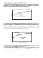
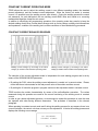
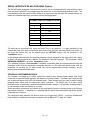
Interface card ITEM 50220 permits the control unit to control a proportional valve and to set, as program
parameter, the welding pressure in bars. This interface requires an external power supply. The 12-pin
terminal strip permits the connection of the proportional valve, the control unit and the interface power
supply.
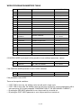
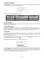
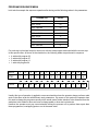
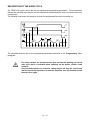
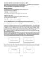
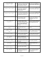
TERMINAL STRIP CONNECTIONS
SV+ from the control unit (PIN 46)
SV- from the control unit (PIN 45)
24Vac
24Vac
Ground
OUT-I
0-10Vdc to the proportional SV
+24Vdc to the proportional SV
Ground to the proportional SV
ALARM-IN
ALARM1 (PIN 33- AUX3)
ALARM2 (PIN 34- COM1)
64
65
66
67
68
69
70
71
72
73
74
75
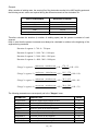
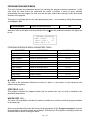
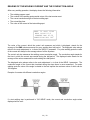
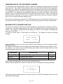
It is possible to program the control voltage range of the proportional valve directly from the weld control
unit. The PRESSURE TRANSDUCER parameter is in the "Installation" menu by means of which it is
possible to select the bar/Volt ratio most suitable for the type of solenoid valve to be used.
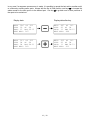
Example:
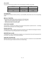
Pressure Parameter bar
5.0
5.0
5.0
Pressure Transducer Parameter bar/Volt
1.0
2.0
0.5
Output Volt
5
10
2.5
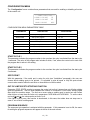
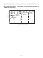
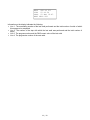
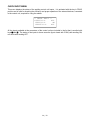
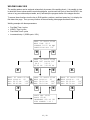
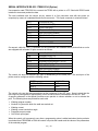
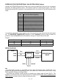
WIRING DIAGRAM
TE500
Pin46
Pin45
Ev+
Ev-
0-10 V
64
70
ITEM 50220
65
71
66 67 68 72
+24 Vdc
PROPORTIONAL
VALVE
Ground
24 Vac
Ground
24 Vac
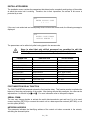
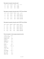
N.B.
_ A red D10 LED is present on card 50220 (near the relay) for indicating when +24VDC (Pin 71) is
present and which goes to the proportional valve. If the LED is OFF check for the correct 24VAC wiring
(Pin66 and Pin67) and ground wiring (Pin68);
_ Card 50220 also contains a small trimmer for regulating the voltage output full scale (Pin70). This
regulation is performed when the required tests are run and therefore MUST NOT be shifted from its
default position so that the value at output will always be exact.
43 / 52