1
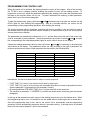
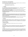
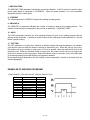
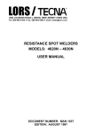
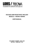
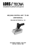
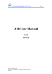
LORS / j
1090 LOUSONS ROAD ♦ UNION, NEW JERSEY 07083 USA
Tel: 908-964-9100 ♦ Fax: 908-964-4492 ♦ email: [email protected]
WELDING CONTROL UNIT: TE 300
USER MANUAL
RELEASE SOFTWARE No. 01
DOCUMENT NUMBER: MAN 4082
EDITION: JANUARY 1998
This page is left blank intentionally.
2 / 18
TABLE OF CONTENTS
SUBJECTS
PAGE
WELDING CONTROL UNIT TE300
4
MAIN TECHNICAL DATA
4
PROGRAMMING THE CONTROL UNIT
5
DESCRIPTION OF THE WORKING CYCLE
6
DESCRIPTION OF THE PARAMETERS
7
EXAMPLES OF WELDING PROGRAMS
8
DOUBLE STROKE FUNCTION
10
USE OF THE "PRESSURE ONLY" CONTROL
11
"CHK" INPUT FUNCTION
12
THERMOSTAT INPUT FUNCTION
12
DELAY FUNCTION OF FIRST PHASE SHIFT
12
COMPENSATION OF THE SECONDARY CURRENT
13
FUNCTION OF ADJUSTMENT TO WELD COS n
13
LAMPS ON THE CONTROL UNIT
14
ERROR LIST
14
SIGNAL DESCRIPTION ON CONNECTORS
15
HANDLE WIRING DIAGRAM
16
TE300 WIRING DIAGRAM
17
3 / 18
WELDING CONTROL UNIT TE 300
The welding control unit is used to control the welder parts and, in particular, the thyristor adjusting the
welding current. TE300 is a microprocessor welding control unit for suspended resistance welding
guns. This control unit includes specific functions to be used when working with suspended welding
guns, such as the double stroke control, and a function checking the efficacy of the safety devices
which can be eventually installed on the handle of the machine. It is possible to program 2 different
welding programs which can be recalled by an external device. Each program is formed by 11
programmable parameters which describe the working cycle. Besides the simple 4 times cycle, the
control unit enables to carry out welding processes with pre-weld current, slope and pulses. Another
available function of this control unit is the compensation of the minimum current.
MAIN TECHNICAL DATA
•
•
•
•
•
•
•
•
•
•
•
Simplified programming by means of 5 push-buttons.
Synchronous thyristors drive with phase shift control for welding current adjustment.
2 welding programs to be stored up and selectable by an external device.
11 programmable parameters for each program.
Slope and pulse functions.
Single and automatic cycle.
Automatic double stroke.
Compensation of the secondary current to weld oxidized sheets and rods.
WELD/NO WELD function.
Delay of first phase shift adjustment to get the best balance of the machine absorption from mains.
Control of 2 solenoid valves 24 Vdc 7.2 W Max with protected output against short circuit: electrode
closing valve and double stroke valve.
• Self-adjustment to the mains frequency 50/60 Hz.
4 / 18
PROGRAMMING THE CONTROL UNIT
When the control unit is activated, the display shows the version of the program. After a few seconds,
the TE 300 is set in a waiting condition enabling the operator to carry out the welding process. To
program the control unit, adjust the parameters describing the welding cycle; select the parameters and
set them to the required values one by one. To better understand the meaning of each parameter,
please look it up on the relevant paragraph.
To start the programming, press push-buttons d and f simultaneously for at least one second: the led
PROG. lights on, thus enabling the programming. After an 8 seconds inactivity, the control unit will
automatically end the programming operations, thus enabling the working.
The working program which is displayed, and which can thus be modified, is the one which is used at
the moment, that is to say the one which can be recalled by an external device (as a rule, a two-position
selector placed on the handle).
The parameters are marked with numbers from 1 to 11, and are listed on the left side of the control unit.
A led is connected to each parameter. Select the parameters by means of buttons d and f , the pilot
line corresponding to the selected parameter lights on and its value is shown on the display.
Change the welding parameters value by means of buttons a and s by increasing or decreasing the
value shown on the display. The parameters values can vary according to the type of parameter, the
minimum and maximum values of each parameter are described in the following table.
PARAMETER NUMBER
1
2
3
4
5
6
7
8
9
10
11
PARAMETER
1° SQUEEZE
SQUEEZE
PRE-WELD TIME
PRE-WELD CURRENT
COLD TIME
SLOPE
WELDING TIME
WELDING CURRENT
IMPULSE NUMBER
HOLD
OFF TIME
RANGE VALUE
00 - 99 cycles
01 - 99 cycles
00 - 60 cycles
01 - 99%
00 - 50 cycles
00 - 29 cycles
01 - 60 cycles
01 - 99%
01 - 09
01 - 99 cycles
00 - 99 cycles
Nevertheless, the above-illustrated table is subject to some exceptions:
• If OFF TIME (11) is set to 0, the control unit will work in single cycle.
• If OFF TIME (11) is set to 99, the control unit will enable the minimum current compensation function
(see the paragraph "Compensation of the secondary current").
• By setting parameter PRE-WELD TIME (3) to 0, the pre-weld will not be carried out.
• The value set in parameter 1° SQUEEZE (1) modifies the double stroke functioning (see the relevant
paragraph).
In this way all the parameters used to carry out the welding process are set to the desired value. When
this programming step is over, it is possible to use the welder without confirming the set or stored data.
Once this programming step is over, wait for the control unit to automatically end the programming
operations; this will automatically take place after an 8 seconds inactivity. If the start device is activated
before this time interval elapses, it will not be considered.
5 / 18
Use the WELD / NO WELD function to carry out any test cycle without
welding current. By means of the here shown proper key, it is possible
to either enable or disable the welding current. When the light is on, the
control unit is set to WELD, and it carries out standard welding cycles.
When the light is off, the control unit is set to NO WELD, and the control
unit carries out complete test cycles without welding current, even
though all the time-relevant parameters are preserved.
During the welding cycle the control unit will display the function being carried out, as well as its value.
When set on a waiting time condition, the control unit will display the number of the selected program,
P1 for program number 1 and P2 for program number 2.
DESCRIPTION OF THE WORKING CYCLE
The TE300 working cycle is described by the user by adjusting 11 programming parameters. These
parameters indicate the operating times and the current adjustments characterizing the working cycles
whenever carried out consecutively. The following chart shows the execution order of the programmed
functions.
The numbers refer to the programming parameters which are described in the following paragraph.
Due to safety reasons, the microprocessor does not start the welding cycle if the cycle start signal is
enabled when the welder is switched on; in this case, disconnect the control and then enable it again.
Any micro-interruptions or excessive voltage drops block the control and do not alter the operation; to
reset the operation, turn the machine off and then turn it on again.
6 / 18
DESCRIPTION OF THE PARAMETERS
All the following parameters indicating a period of time are expressed in periods, also called mains
cycles. The mains frequency defines the duration of a cycle.
Mains frequency 50 Hz 1 period = 20 ms
Mains frequency 60 Hz 1 period = 16.6 ms
1 - 1°SQUEEZE
The 1° SQUEEZE time is used when working with automatic double stroke. It determines the electrode
shifting time from the long stroke position to the short stroke one.
The set value must be long enough to have the mobile electrode reach the short stroke position.
Set the 1° SQUEEZE value to 0, to adjust the control for the fixed short stroke; set it to 99 to get the
fixed long stroke (see the relevant paragraph).
During the first squeeze time, it is possible to end the cycle if the start cycle signal is disconnected.
This parameter can be set only if the welder and its handle foresee the control of the double
stroke from the control unit.
2 - SQUEEZE
The SQUEEZE time determines the electrodes closing time, that is to say the time interval between the
beginning of the electrodes closing and the starting of the welding process. The set value must be long
enough to have the electrodes reach both the piece to weld and the proper clamping force before the
starting of the welding process.
A too low adjustment of this time causes sparkles between electrodes and sheet when the welding
process starts; it can also cause an irregular welding quality.
If the start cycle signal is deactivated during the squeeze time, the sequence is disconnected.
3 - PRE-WELD
The PRE-WELD parameter indicates the length of a passage which can be carried out before the
welding process in order to pre-heat the piece to be welded. If this parameter is set to 0, the pre-weld
will not be carried out. The pre-weld will be carried out at a current adjustment equal to that stated on
parameter 4 (CURRENT).
4 - PRE-WELD CURRENT
The value expressed in this parameter indicates the power used to carry out the pre-weld.
5 - COLD TIME
The COLD 1 parameter, or cool time, is used during the pulses operation in order to indicate the time
elapsing between a welding impulse and the following one. If the pre-weld is enabled (that is, when the
PRE-WELD time is other than 0), this cool time is also used between the pre-weld and the weld.
6 - SLOPE
The SLOPE parameter describes the time during which the programmed value of welding power has
been reached. The initial value of this slope always corresponds to the minimum power, while the final
value corresponds to the value of power being programmed in parameter 8 (CURRENT). The slope
speed is automatically calculated by the microprocessor according to the programmed values. The
SLOPE time is summed to the welding time.
7 / 18
7 - WELDING TIME
The WELDING TIME parameter indicates the current flow duration. It will be carried out with the same
power value stated on parameter 8 (CURRENT). When the pulse operation is on, this parameter
signals the duration of each pulse.
8 - CURRENT
The value expressed in CURRENT indicates the welding operating power.
9 - IMPULSE N.
The IMPULSE N. parameter indicates the number of impulses used for the welding process. The
duration of each impulse corresponds to the time set on parameter 7 (WELDING TIME).
10 - HOLD
The HOLD parameter describes the time elapsing between the end of the welding process and the
opening of the electrodes. It enables a quicker cooling of the welding spot and avoids that is, it moved
before a proper cooling.
11 - OFF TIME
The OFF parameter, or waiting time, indicates a machine waiting time elapsing between one machine
cycle and the next one when the welder is working in automatic cycle. When this value is set to zero,
the machine will go on working in single cycle; if it is set to another value, the machine will work in the
automatic cycle. When the machine works in single cycle, the control unit will carry out a single cycle
each time it receives a start cycle signal. When the machine works in automatic cycle, the welder goes
on executing welding cycles until the start cycle signal is released.
By programming this parameter to 99 the welding current compensation function is activated (see the
relevant paragraph).
EXAMPLES OF WELDING PROGRAMS
4 TIMES SIMPLE CYCLE WITH SHORT STROKE, SINGLE CYCLE
NUMBER
1
2
3
4
5
6
7
8
9
10
11
PARAMETER
1° SQUEEZE
SQUEEZE
PRE-WELD
PRE-WELD CURRENT
COLD TIME
SLOPE
WELDING TIME
CURRENT
IMPULSE N.
HOLD
OFF TIME
VALUE
00 cycles
20 cycles
00 cycles
01 %
00 cycles
00 cycles
16 cycles
40%
01
09 cycles
00 cycles
8 / 18
CYCLE WITH PULSES AND SLOPE, LONG STROKE, AUTOMATIC CYCLE
NUMBER
1
2
3
4
5
6
7
8
9
10
11
PARAMETER
1° SQUEEZE
SQUEEZE
PRE-WELD
PRE-WELD CURRENT
COLD TIME
SLOPE
WELD TIME
CURRENT
IMPULSE N.
HOLD
OFF TIME
VALUE
99 cycles
40 cycles
00 cycles
01%
07 cycles
06 cycles
08 cycles
40%
03
09 cycles
35 cycles
CYCLE WITH PRE-WELD, SLOPE, AUTOMATIC STROKE, AUTOMATIC CYCLE
NUMBER
1
2
3
4
5
6
7
8
9
10
11
PARAMETER
1° SQUEEZE
SQUEEZE
PRE-WELD
PRE-WELD CURRENT
COLD TIME
SLOPE
WELD TIME
CURRENT
IMPULSE N.
HOLD
OFF TIME
VALUE
20 cycles
30 cycles
08 cycles
20%
10 cycles
04 cycles
12 cycles
60%
01
09 cycles
40 cycles
CYCLE WITH PRE-WELD, AUTOMATIC STROKE, AUTOMATIC CYCLES, NO COLD TIME BETWEEN
PRE-WELD AND WELD
NUMBER
1
2
3
4
5
6
7
8
9
10
11
PARAMETER
1° SQUEEZE
SQUEEZE
PRE-WELD
PRE-WELD CURRENT
COLD TIME
SLOPE
WELD TIME
CURRENT
IMPULSE N.
HOLD
OFF TIME
VALUE
20 cycles
30 cycles
08 cycles
20%
00 cycles
00 cycles
12 cycles
60%
01
09 cycles
40 cycles
COMPLEX CYCLE WITH PRE-WELD, SLOPE, PULSES, AUTOMATIC STROKE, AUTOMATIC CYCLE
NUMBER
1
2
3
4
5
6
7
8
9
10
11
PARAMETER
1° SQUEEZE
SQUEEZE
PRE-WELD
PRE-WELD CURRENT
COLD TIME
SLOPE
WELD TIME
CURRENT
IMPULSE N.
HOLD
OFF TIME
VALUE
30 cycles
20 cycles
08 cycles
20%
10 cycles
04 cycles
12 cycles
60%
02
09 cycles
40 cycles
9 / 18
DOUBLE STROKE FUNCTION
The double stroke function is enabled only when the control unit is equipped with a handle
enabling this function. This function is deactivated on all machines which are not designed for
the double stroke control; as a consequence, it is not possible to set 1° SQUEEZE parameter.
The solenoid valve EV2 output drives the double stroke solenoid valve. When the machine is switched
on, it is always deactivated even though the control unit is programmed for working with the short
stroke. The OPEN input is connected to a push-button close to the operator, which is used to have the
double stroke deactivated (electrodes opening).
The operator, by means of the 1° SQUEEZE parameter, selects one among the three possible working
modes, here after explained.
WORKING STROKE (SHORT)
A
B
TOTAL STROKE (LONG)
A - MOBILE ELECTRODE POSITION WITH DISCONNECTED DOUBLE STROKE (LONG STROKE)
B - MOBILE ELECTRODE POSITION WITH OPERATING DOUBLE STROKE (SHORT STROKE)
SHORT STROKE
By setting the 1° SQUEEZE parameter value to 0, the operator adjusts the control unit for the short
stroke. Under this mode, the solenoid valve EV2 is kept activated, and the mobile electrode, under the
rest condition, will be on "B" position.
If the operator needs to open the electrodes while working, he will press the "double stroke opening"
push-button; it, by means of the OPEN input, disconnects the solenoid valve EV2. After having pressed
the "double stroke opening" push-button, or when switching the welder on, the electrode is placed on
"A" position; the control unit will move it to "B" position, when the first weld is carried out.
During the first weld, TE300 activates the solenoid valve EV2 (which shifts the electrode from "A" to "B"
position), then it awaits for a 0.6 seconds fixed time and finally it carries out the programmed welding
cycle. When the weld has been carried out, the solenoid valve EV2 is not deactivated and the electrode
is kept on "B" position. The following welds will be carried out starting from this position.
It is possible to shift the electrodes from the long stroke position to the short one by means of the
control "PRESSURE ONLY" (see paragraph "USE OF PRESSURE ONLY CONTROL").
Notice that each time the programming of the control unit starts, the double stroke solenoid valve EV2 is
deactivated.
LONG STROKE
By setting the 1° SQUEEZE parameter value to 99, the operator adjusts the control unit for the long
stroke. Under this mode, the solenoid valve EV2 is kept deactivated, and under the rest condition, the
mobile electrode will be on "A" position.
In this case, the OPEN input activation has no effect. During the welding cycle, the 1° SQUEEZE time
is not carried out.
10 / 18
AUTOMATIC STROKE
By setting the 1° SQUEEZE parameter to a value included between 1 and 99, the operator adjusts the
control unit for the automatic stroke. This mode is used together with the automatic cycle functioning
(parameter OFF# 0). It enables to carry out sequences of welding cycles with the short stroke, but
starting from a long stroke working condition, that which, for instance, is useful for positioning the
welding gun on the piece to weld.
On START, the control unit activates the solenoid valve EV2 (which shifts the electrode from A to B
position) and, before the activation of EV1, it carries out the programmed 1° SQUEEZE time. When
the first weld of the automatic cycle is carried out, the EV2 is not disconnected and the 1° SQUEEZE is
ignored for the following welds. This goes on until the operator does not release the start of cycle
control device, thus ending the welds sequence, the control unit disconnects both EV1, and EV2, which
returns the electrodes to the maximum opening. If the double stroke is activated before the starting of
the welding process, the control will not carry out the 1° SQUEEZE time.
USE OF THE "PRESSURE ONLY" CONTROL
The "PRESSURE ONLY" control is usually used to check that the electrodes are correctly positioned
before carrying out the welding process.
By activating the PRESSURE ONLY control (usually by pressing a push button placed on the welder
handle) while the electrodes are closing, the welder clamps the pieces to weld and waits; the operator,
after having checked the correct positioning of the electrodes, enables the cycle to continue by
deactivating the control PRESSURE ONLY (releasing the push button). If the electrodes are not
correctly positioned, the operator can cancel the operation by releasing the start of cycle device.
For welders with double stroke control only:
If the control unit has been set to "short stroke" mode (1° SQUEEZE = 0) the control PRESSURE
ONLY device can be used to shift the electrodes from "long stroke" position to "short stroke" position,
without closing the electrodes on the workpiece. This operation is sometimes necessary for particular
welding conditions (i.e. works on thin thickness or requiring high precision).
The electrodes can be placed in a "long stroke" position either because they have been opened by
means of the OPEN control, or because the welder has just been switched on.
When starting the welding cycle, TE300 brings the electrodes to "short stroke" position, thus activating
the solenoid valve EV2, in 0.6 seconds. If the control PRESSURE ONLY is activated, the welding cycle
stops in this position. By keeping this condition for one second and then deactivating the start of cycle
control, the electrodes stay in the "short stroke" position.
If the PRESSURE ONLY control is released the cycle continues and the welding is accomplished.
11 / 18
"CHK" INPUT FUNCTION
On the handle of the suspended welding gun there can be installed a safety micro-switch carrying out a
special function: it enables to start the cycle only if the operator has previously grasped the handle. As
a rule, this micro-switch is placed in series to the start of cycle one. In order to get a better safety, the
control unit, by means of the CHK input, checks that this input is activated when the welding process
starts. If the signal is not activated, the TE300 does not accept the start of cycle signal; the following
message will be displayed:
Moreover, the control unit checks that this micro-switch is neither broken (it keeps closed), nor
tampered. This test is carried out:
● when switching the control unit on
● when pressing the double stroke opening push-button
● when shifting from RUN to PROGRAM
Under these conditions, the control unit displays the following error message, and it does not enable the
welding process. The error does not block the machine functioning; the error will be automatically
cleared, when its cause is removed.
THERMOSTAT INPUT FUNCTION
This input is connected to a normally closed thermostat which is placed on the welder. When starting
the welding cycle, if the following error message is displayed:
It is to mean that the thermostat got open. It is not possible to carry out welding processes until the
thermostat is reset.
DELAY FUNCTION OF FIRST PHASE SHIFT
This function allows to obtain the best machine line current balance. To adjust it, set to CURRENT (8)
parameter and simultaneously press push-buttons d and f for about one second to carry out the
adjustment. The CURRENT (8) function lamp flashes and the display shows the new set value. As
usual, the adjustment is carried out by pressing push-buttons a and s .
The value can be set from 35 up to 99. When the programming is over, press d or f . As this
adjustment is carried out by the welder manufacturer, the user does not need to modify this value.
12 / 18
COMPENSATION OF THE SECONDARY CURRENT
The compensation function of secondary current is used to facilitate the welding process of oxidized
sheets and rods. The pieces oxidation blocks the current flow during the first welding phase, thus
limiting, in a different way depending from the welding process, the real time of current flow. The
compensation function controls the welding current by means of a coil located inside the secondary
circuit. Until the welding current does not exceed a pre-set limit, the welding time is automatically
extended up to a limit of 60 cycles. In this way it is possible to carry out welding processes with an
always constant real time of current flow. If, after having reached the 60 welding periods limit, the
current limit is not exceeded, the control unit will indicate that the welding process has not been
correctly carried out by displaying the E3 error, and will block the welder functioning. To restore the
functioning, press any push-button.
The current limit is adjusted by the welder manufacturer by means of the welder manufacturer. The
standard value is usually about 1500=2000 A. By means of JP1 jumper, located on the card, is possible
to disable this function:
COMPENSATION
JUMPER JP1
ON
OFF
OPEN
CLOSED
This function is enabled by setting the parameter 11 (OFF TIME) value to 99; when this function is
enabled, the control unit will work in single cycle.
FUNCTION OF ADJUSTMENT TO WELDER COS n
In resistance welders the phase displacement between the mains voltage and the absorbed current (i.e.
cos n) changes according to the transformer characteristics, the dimensions of the secondary circuit
and the material to be welded.
TE300 has an adjustment trimmer called "cos n" enabling to suit the control to the cos n of the welding
machine on which it is installed.
This set up is made by the welder manufacturer, hence the user does not need to make any calibration.
13 / 18
LAMPS ON THE CONTROL UNIT
If on, it indicates that the start of cycle control triggered by the pushbutton placed on the handle is enabled.
It indicates that the external device recalling the welding program no.
2 is enabled.
When this lamp switches on, it indicates that the stop-with-onlypressure device is enabled. This input is normally activated by the
"PRESSURE ONLY" selector.
When this lamp switches on, it indicates that the control unit is
generating the SCR trigger impulses.
It indicates that the solenoid valve executing the main cycle is
enabled.
It indicates that the solenoid valve driving the double stroke is
enabled.
When this lamp flashes, it indicated that the control unit is carrying
out the programming. When this lamp is off, it indicates that the
control unit is ready for carrying out welding cycles.
ERRORS LIST
MESSAGE
CAUSE
REMEDY
The value of one of the stored parameters
exceeds the pre-set limits. This could be caused
by a loss of data due to any interference or faulty
functioning.
Press a push-button to clear the error.
Check all the values being set in the
parameters and correct them if necessary.
Address to the after-sale service if the
trouble reoccurs frequently.
You are pulse operating and the total welding
time (pre-weld time + welding time x impulse no.)
is higher than 120 cycles. It is not possible to
exceed this value in order to avoid the welder
overheating.
Press a push-buttons to clear the error.
Reduce either the welding time or the
impulse number so to have a total welding
time lower than 120 cycles.
The compensation function is enabled and the
control unit has extended the welding time up to
the maximum limit corresponding to 60 periods.
The set welding time has not been carried out
with a welding current higher than the fixed limit.
Press a push button to clear the error.
Before restart the welding process, check
the welding conditions. If the pieces are
too oxidized they must be cleaned.
The built-in protection thermostat has been Check that the correct water quantity is
activated.
running inside the welder and/or check the
thermostat correct functioning.
The CHK signal indicates that the safety device Check.
placed on the handle is working. This could be
caused by either damage or tampering.
14 / 18
SIGNALS DESCRIPTION ON CONNECTORS
CONNECTOR XS1 (12 PINS)
NUMBER
NAME
MEANING
5-7
VAC
It is the control unit supply, which must be 24 Vac. The supply
transformer must supply only the control unit in order to avoid
possible troubles sources.
12
GND
Earthing. Connect to earth the output common line COM 2.
8
1
TRG +
COM 2
Output for the trigger signal for the SCR. It is necessary to use the
TECNA firing module for the SCR control.
4
3
ROG
ROG
The current transducer (rogowski ring) must be connected to this
analog input. The used transducer must have a 150 mV/kA
sensitivity with a loading of 1 k Ω.
9
2
EV1
COM 2
Connect to the solenoid valve acting the cycle. Proper command for the
24Vac coil pilot system max 7.2 W coil.
11
10
TERM
COM 1
This input has been designed for connecting a normally closed
thermostat.
6
2
EV2
COM 2
Connect to the solenoid valve driving the double stroke.
command for the 24 Vac max 7.2 W coil.
Proper
REMARK: The outputs EV1, EV2, TRG+ are protected against short circuit thanks to electronic devices
with automatic restart.
CONNECTOR XS2 (6 PINS)
NUMBER NAME
START
4
COM 1
5
MEANING
Connect to the start of cycle device microswitches.
active closed on the common COM 1.
Both inputs are
3
5
AUX
COM 1
This input allows an external device to block the welding cycle during
the squeeze phase. It is normally used for the "ONLY PRESSURE"
function. The contact connected to this input must be of the normally open
type.
2
5
RIC2
COM 1
This input enables the welding program No. 2 direct recall from
outside. For a correct direct recall of the program, this input must be
enabled before the start cycle signal. The input is working when closed
towards common line COM 1.
OPEN
COM 1
It is connected to the "OPEN" micro-switch, placed on the welder handle.
It enables the double stroke opening. This input is working when closed
towards common line COM 1.
In the handles which are not equipped with this function, OPEN signal is
always in short-circuit with the common COM 1. This indicates to the
control that the double stroke function must not be carried out.
CHK
COM 1
Input used to check the safety function eventually installed on the handle.
This input is working when closed towards common line COM 1. If this
function is not used because the handle is not equipped with this
microswitch, short-circuit this input with the START one (pin 4).
By this operation, the safety function against the accidental
triggering is disabled.
6
5
1
5
15 / 18
16 / 18
17 / 18
OBSERVATIONS
18 / 18