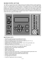
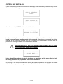
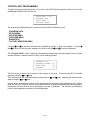
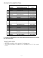
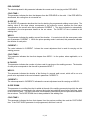
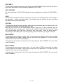
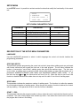
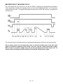
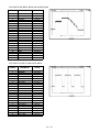
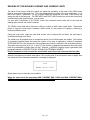
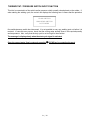
1
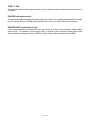
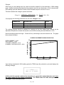
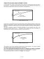
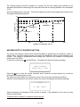
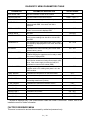
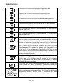
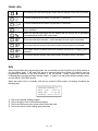
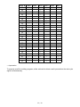
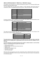
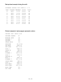
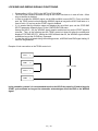
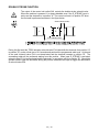
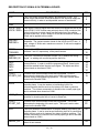
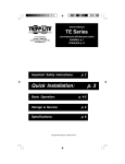
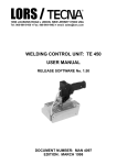
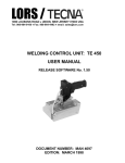
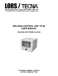
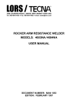
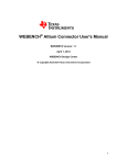
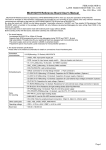
LORS / j
1090 LOUSONS ROAD ♦ UNION, NEW JERSEY 07083 USA
Tel: 908-964-9100 ♦ Fax: 908-964-4492 ♦ email: [email protected]
WELDING CONTROL UNIT: TE 600
USER MANUAL
RELEASE SOFTWARE No. 6.08
EDITION: JUNE 2007
This page is intentionally left blank.
2 / 42
TABLE OF CONTENTS
TOPICS
PAGE
TE600 WELDING CONTROL UNIT
4
MAIN TECHNICAL DATA
4
CONTROL UNIT SWITCH-ON
5
CONTROL UNIT PROGRAMMING
6
DESCRIPTION OF THE PROGRAM PARAMETERS
8
SETUP MENU
11
DESCRIPTION OF THE SETUP MENU PARAMETERS
11
STEPPER MENU
13
WELDING SPOTS COUNTER FUNCTION
18
INSTALLATION MENU
19
DESCRIPTION OF THE INSTALLATION MENU PARAMETERS
19
DIAGNOSTICS MENU
20
FACTORY RESERVED MENU
21
PANEL CONTROLS
22
PANEL LEDs
23
RUN
23
SELECTION OF THE WORK PROGRAM
24
DESCRIPTION OF THE WORK CYCLE
26
EXAMPLES OF WELDING PROGRAMS
27
READING OF THE WELDING CURRENT AND CURRENT LIMITS
30
THERMOSTAT/PRESSURE SWITCH INPUT FUNCTION
31
SERIAL INTERFACE RS-232
32
INTERFACE FOR PROPORTIONAL VALVE
34
LOCK/END AND WRONG SIGNALS FUNCTIONING
35
DOUBLE STROKE FUNCTION
36
LIST OF MESSAGES
37
DESCRIPTION OF SIGNALS ON TERMINAL BOARD
40
3 / 42
WELDING CONTROL UNIT TE 600
The TE600 is a microprocessor-based welding control unit for resistance welders in inverter technology.
The task of the welding control unit is to manage the welder's components, in particular the IGBT power
booster unit, which regulates the welding current. It is possible to store up to 63 different welding
programs, all of which can be directly recalled from an external device. Each program comprises 22
programmable parameters that describe the work cycle. In addition to the basic 4-stage welding cycle,
the control unit allows the running of welding processes with pre-welding current, post-welding current,
slopes and pulses. The TE600 works in constant current mode, it visualizes the weld current and
controls the current supplied with settable limits.
2
1
2
3
4
MADE IN ITALY
MAIN TECHNICAL DATA
•
•
•
•
•
•
•
•
•
•
•
•
•
•
•
•
•
•
Simplified programming by 6 keys and alphanumeric LCD.
Inverter command with IGBT at medium frequency 1000 Hz.
Storage of 63 welding programs, all of which are recallable from PLC, PC, etc.
22 programmable parameters for each program.
Stepper function for compensating the electrodes’ wears with programmable curve.
Weld times adjustable in 1ms increments.
Visualization of the welding current in kA and limits of the welding current.
Automatic double stroke function (for the applicable welders).
Proportional valve for controlling the welding pressure.
Welds-performed counter.
Single and automatic cycle.
WELD / NO WELD function.
Control of 4 solenoid valves 24 Vdc Max. 7.2 W with output protected against short circuit.
Welding current limits with output for signalling out-of-limits welds.
Outputs for interfacing with external devices (Interlock/End cycle).
Automatic voltage compensation.
Five languages can be selected.
Possibility of updating the control unit hardware.
4 / 42
CONTROL UNIT SWITCH-ON
As soon as the welding control unit is turned on, the display shows the primary mains frequency and the
software version of the program.
SUPPLY FREQUENCY
50 Hz.
TECNA TE600 6.08
WELD CONTROL UNIT
After a few seconds, the TE600 switches to standby status.
PUSH KEY[//]
RESTART TO CONTINUE
Press the restart key for one second to enable the controls and the outputs of the control unit.
It must be pressed every time the control unit is powered. When the key is pressed all the devices
connected to the VAUX are powered such as for example the double stroke valve and then the
procedure for charging the battery of the capacitors is activated.
k
Before pressing the key it is important to check that it will not cause
injury/damage to people or equipment.
CAPACITOR SUPPLIED
...PLEASE WAIT....
It takes about 20 seconds for the device to charge the capacitors and be ready either to begin
the welding operations or program the values of the parameters.
On powering up the control unit and before starting any welding operations, first program the welding
data and set some general operating parameters of the welder.
5 / 42
CONTROL UNIT PROGRAMMING
To begin the programming operations, turn the key in the PROG position and be aware of some of the
fundamental features of the control unit.
TE600 VER. 6.08
> PROGRAM DATA
SETUP MENU
FEATURES MENU
The programming parameters of the control unit are divided into different menus:
_ PROGRAM DATA
_ SETUP MENU
_ STEPPER MENU
_ FEATURES MENU
_ DIAGNOSTIC
_ FACTORY RESERVED MENU
Use keys d and f to select the desired menu, identified by symbol ">" next to the caption. Use keys g
and h to enter and exit the menu whereas you should use keys a and s to set the parameters.
The "Program DATA" menu contains all the parameters associated with the welding cycle, the times
and the currents by means of which to carry out the welding process.
PROGRAM DATA
> PROGRAM NUMBER
WORK MODE
SQUEEZE 1
01
IK
30
The first choice to make is the number of the program to be used. Choose among the 63 storable
programs using the a and s keys.
Then proceed with the next parameters moving with the d and f keys, adjusting the desired value
always using the a and s keys.
As such all the parameters will be set to the desired value for carrying out the welding process. Keep in
mind that there is no need to confirm the set data item that is stored automatically after the adjustment.
Parameters can have several values, according to the type of parameter. The minimum and maximum
limits of each parameter are shown in the following table.
6 / 42
PROGRAM DATA PARAMETERS TABLE
PARAMETER
DESCRIPTION
VALUE RANGE
PROGRAM N.
PROGRAM NUMERIC SELECTION
WORK MODE
WORK MODE
STROKE
DUAL STROKE MODE
1
SQUEEZE 1
1ST SQUEEZE TIME
01 – 99 cycles
2
SQUEEZE *
SQUEEZE TIME
01 – 99 cycles
3
FORGING *
FORGE DELAY
00 – 99 cycles
4
PRESSURE *
WELDING PRESSURE
00.5 – 10.0 bar
5
PRE-WELD
PRE-WELD time
0000 – 1000 ms
6
PRE-CURRENT
PRE-WELD CURRENT
000.3 – 120.0 kA
7
COLD T. 1
COLD TIME 1
0000 – 1000 ms
8
SLOPE UP
SLOPE UP TIME
000 – 500 ms
9
WELD 1
WELDING TIME
0001 – 1000 ms
10
CURRENT 1
WELDING CURRENT
000.3 – 120.0 kA
11
COLD T. 2
COLD TIME 2
0000 – 1000 ms
12
N. OF PULSES
PULSES
13
WELD 2
SECOND WELDING TIME
0000 – 1000 ms
14
CURRENT 2
SECOND WELDING CURRENT
000.3 – 120.0 KA
15
SLOPE DOWN
SLOPE DOWN TIME
16
COLD T. 3
COLD TIME 3
0000 – 1000 ms
17
POST-WELD
POST-WELD TIME
0000 – 1000 ms
18
POST-CURR
POST-WELD CURRENT
000.3 – 120.0 kA
19
HOLD
HOLD TIME
03 - 99 cycles
20
OFF TIME
DWELL TIME
00 - 99 cycles
21
CURR MIN.
MIN. LIMIT IN CURRENT
000.3 – 120.0 kA
22
CURR MAX.
MAX. LIMIT IN CURRENT
000.3 – 120.0 kA
01 - 63
IK
SHORT
0–5
000 – 500 ms
(*) _ In order to view these parameters in the welding program they must be activated in the installation
menu (see specific section).
There are few special conditions:
• If OFF TIME is set to (0), the welding control unit will work in single cycle.
• When parameters PRE-WELD and/or WELD 2 and/or POST-WELD are set to (0), said cycles will
not be run.
7 / 42
DESCRIPTION OF THE PROGRAM PARAMETERS
As far as the parameters that indicate times expressed in milliseconds are concerned, the mains
frequency (50/60 Hz) does not change the duration of the set time whereas for all those parameters that
indicate times expressed in periods, also called mains cycles, the main frequency determines the
duration of one period:
Mains frequency of 50 Hz 1 period = 20 ms
Mains frequency of 60 Hz 1 period = 16.6 ms
WORK MODE
This parameter defines the mode for adjusting the welding current at constant current (IK).
SQUEEZE 1
If a pneumatic circuit is present with low-pressure squeeze, such time is that which determines
duration of the squeeze at low pressure, i.e. the interval of time that elapses from the beginning of
head descent to the application of the welding force. The set value must be long enough to allow
electrodes to reach the workpiece to be welded.
In a standard pneumatic circuit, such time is the interval from the beginning of the head descent to
beginning of the welding. The set value must be long enough to allow the electrodes to achieve
proper clamping force, before the welding begins.
During the first squeeze time, it is possible to end the cycle if the start cycle signal is deactivated.
the
the
the
the
the
SQUEEZE
The SQUEEZE determines the closing time of the electrodes, i.e. the time interval between the
beginning of the closing of the electrodes and the beginning of the weld. The set value must be long
enough to permit the electrodes to reach the workpiece to be welded and to attain the correct clamping
force before the weld begins.
An inadequate adjustment of such time produces sparks among the electrodes and the sheet when the
welding begins, causing quality inconsistencies.
If the start cycle signal is deactivated, during the squeeze time, the sequence is interrupted.
FORGE DELAY
The FORGE DELAY parameter is used exclusively with pneumatic circuits that have a forging function
capability. Such function permits increasing the electrode force during the welding cycle. The
parameter describes the time that elapses from the beginning of the welding process to the application
of the forging force onto the electrodes by means of solenoid valve EV3. If the value is set to zero the
forging function is disabled and valve EV3 will be activated at the beginning of the squeezing phase.
PRESSURE
This parameter, expressed in bar or psi, expresses the welding pressure value. The set value must be
such that it guarantees a proper clamping force during the welding cycle. An inadequate adjustment of
such value produces sparks between electrodes and sheet when the welding begins.
PRE-WELD
The PRE-WELD parameter indicates the duration of a current flow that can be carried out before the
welding process so as to pre-heat the workpiece to be welded. If this parameter is set to (0), the preweld will not be carried out. Pre-weld is carried out with a current adjustment equal to that stated in the
PRE-CURR parameter.
8 / 42
PRE-CURRENT
The value expressed in this parameter indicates the current used for carrying out the PRE-WELD.
COLD TIME 1
This parameter indicates the time that elapses from the PRE-WELD to the weld. If the PRE-WELD is
deactivated, this cooling time is not carried out.
SLOPE UP
The SLOPE UP parameter describes the time for attaining the programmed welding current value. The
starting value of this slope always corresponds to the minimum current, whereas the final value
corresponds to the current value set at parameter CURRENT 1. The slope inclination is automatically
calculated by the microprocessor based on the set values. The SLOPE UP time is added to the
welding time.
WELD 1
This parameter indicates the welding current flow duration. It is carried out with the same power value
set at parameter CURRENT 1. When the pulse operating mode is activated, this parameter indicates
the duration of each pulse.
CURRENT 1
The value indicated in CURRENT 1 shows the current adjustment that is used for carrying out the
welding process.
COLD TIME 2
This parameter indicates the time that elapses from WELD 1 to the pulses, where applicable, or to
WELD 2.
N. PULSES
This parameter indicates the number of pulses used for carrying out the welding process. The duration
of each pulse corresponds to the time set in parameter WELD 1.
WELD 2
This parameter indicates the duration of the flowing of a second weld current, which will be run at a
power value equivalent to the one indicated in parameter CURRENT 2.
CURRENT 2
The value expressed in CURRENT 2 indicates the current adjustment used for carrying out WELD 2.
SLOPE DOWN
This parameter is a welding time that is added at the end of the welding process during which the weld
current decreases, as compared to the value set during the last weld that comes before said time, down
to the minimum value. The slope inclination is automatically calculated by the microprocessor based on
the set values. The SLOPE DOWN time is always added to the welding time.
COLD TIME 3
This parameter indicates the time that elapses from the previous welding time and the POST-WELD
time. If the POST-WELD parameter is not programmed, said time is not run.
9 / 42
POST-WELD
This parameter indicates the duration of the flowing of the POST-WELD current, which will be run at a
power value equivalent to the one indicated in parameter POST-CURR.
POST-CURRENT
The value expressed in POST-CURR indicates the current adjustment with which the POST-WELD is
run.
HOLD
This parameter indicates the time that elapses from the end of the welding process to the opening of
the electrodes. It allows a quicker cooling of the welding spot and prevents the spot from being
stimulated before being properly cooled.
OFF-TIME
This parameter indicates a welder wait time, namely the one that elapses from one welding cycle to the
next one when the welder is working in automatic cycle.
When this value is set to zero, the welder always works in single cycle; if it is set to another value, the
welder will work in the automatic cycle. When the welder works in single cycle, the control unit carries
out a single welding cycle each time it receives a start cycle signal. When the welder works in
automatic cycle, the welder goes on executing welding cycles until the start cycle signal is released.
MIN CURRENT
This parameter fixes a minimum current value. For each weld, the TE600 monitors that the welding
current supplied by the welder is higher than the value set at this parameter; if it is lower, an error
condition occurs (see the relevant paragraph).
If this parameter is actually set for the same value of the parameter “MAX CURRENT” the current limits
control is disabled.
MAX CURRENT
This parameter fixes a maximum current value. For each weld, the TE600 monitors that the welding
current supplied by the welder is lower than the value set at this parameter; if it is higher, an error
condition occurs (see the relevant paragraph).
If this parameter is actually set for the same value of the parameter “MIN CURRENT” the current limits
control is disabled.
10 / 42
SETUP MENU
In the SETUP menu it is possible to activate certain functions that modify the functionality of the control
unit.
SETUP
> LANGUAGE
ENG
STOP BAD SPOTS 0
SPOTS MAX
00000
SETUP MENU PARAMETERS TABLE
PARAMETER
DESCRIPTION
VALUE RANGE
LANGUAGE
Language for parameter description
ITA-ENG-ESP-DEU-FRA
STOP BAD SPOTS
Number of spots for out-of-limit stop
0-9
SPOTS MAX
Maximum number of spots
START 1 PRG
Start cycle 1 program
00 - 63
START 2 PRG
Start cycle 2 program
01 - 63
PRINTER
Printing of weld data
ON - OFF
PRINTER SPOTS
Printing of welding spots
00000 - 60000
ALL - GOOD - BAD
DESCRIPTION OF THE SETUP MENU PARAMETERS
LANGUAGE
Use the LANGUAGE parameter to select in which language the control unit should visualize the
programming parameters.
STOP BAD SPOTS
This parameter permits programming the control unit so that it stops when welding spots are performed
with current values that are beyond the limits set in the weld program. The set value indicates the
number of consecutive "out-of-limits" welding spots after which the machine stops. The limit error
occurs when a welding spot is carried out with values either higher or lower than the limits set in
parameters “MINIMUM CURRENT (MIN CURR)” and “MAXIMUM CURRENT (MAX CURR)”. To set
the value use keys a and s ; the value can be set from (0) to (9). When the value is set to zero, this
function is disabled therefore the welder does not stop even in case of "out-of-limits" welding spots.
SPOTS MAX
This parameter indicates the maximum number of welding spots. The function is to allow the operator
to run the desired number of welding spots. When the pre-set number of welds is attained, the control
will stop welding. If this parameter is set to zero the function is disabled.
START 1 PRG
This parameter indicates the program number to be run when the cycle is activated via the start cycle 1
command. The value of the program also includes (0) which, if set, allows the control unit to work with
the program that is active in the setting.
11 / 42
START 2 PRG
This parameter indicates the program number to be run when the cycle is activated via the start cycle 2
command.
PRINTER (with optional card)
This parameter enables/disables the printing both of the values of the welding parameters that is carried
out by switching the key to WORK position and the values of the run weld, at the end of each spot.
PRINTER SPOTS (with optional card)
If the previous parameter is activated the user may choose, by means of this parameter, which welding
spots to print. It is possible to print all spots (ALL) or choose to print only those whose current value
remains within the programmed limits (GOOD) or those whose value is beyond the limits (BAD).
12 / 42
STEPPER MENU
The "Stepper" menu contains parameters associated with the current stepper operations.
--- STEPPER --> NUM. INCREMENTS 01
SPOTS 1
4000
INCREMENT 1
12%
STEPPER MENU PARAMETERS TABLE
PARAMETER
DESCRIPTION
VALUE RANGE
TOTAL STEPS
Number of incremental steps
01 - 07
SPOTS 1
Spots step 1
0 - 10000
INCREMENT-1 %
Percent increment step 1
0 - 50
SPOTS 2
Spots step 2
0 - 5000
INCREMENT 2 %
Percent increment step 2
0 - 50
SPOTS 3
Spots step 3
0 - 5000
INCREMENT 3 %
Percent increment step 3
0 - 50
SPOTS 4
Spots step 4
0 - 5000
INCREMENT 4 %
Percent increment step 4
0 - 50
SPOTS 5
Spots step 5
0 - 5000
INCREMENT 5 %
Percent increment step 5
0 - 50
SPOTS 6
Spots step 6
0 - 5000
INCREMENT 6 %
Percent increment step 6
0 - 50
SPOTS 7
Spots step 7
0 - 5000
INCREMENT 7 %
Percent increment step 7
0 - 50
NUM. OF INCREMENTS
This parameter indicates how many segments are to be created for implementing the stepper curve.
Only the parameters that describe the desired function will be displayed in relation to the set value.
SPOTS 1,2,3,...
Each of these parameters indicates the number of spots of which the associated segment is composed.
INCREMENT 1,2,3,...
These parameters indicate the current stepper percent to be attained upon the completing of the spots
set in the associated segment.
13 / 42
CURRENT STEPPER FUNCTION
The stepper function enables to compensate the wear of the electrodes that affects the quality of the
welding spots. When the electrode diameter is enlarged, the contact section area between the
electrode and the workpiece to be welded increases and, as a consequence, the welding current
density (Ampere/mm2) decreases. If the current is maintained at a fixed value throughout the whole
electrode life, it will be noticed that the quality of the last spots is poorer than the first ones. The stepper
function is used for overcoming this problem. It gradually increases the current adjustment during the
welding process when the diameter of the electrodes increases: this enables to maintain a constant
weld current density.
An increment curve is programmed to describe the pattern of the current during the electrodes' life.
This curve is described by one or more segments for each of which the number of welding spots and
the associated current increment in percent are programmed.
After it has been set, the current increment is applied to all the welding programs used.
The current limits, if used, increment by the same percent. The same holds true for the pre-weld and
post-weld current adjustments.
If the set welding current values are changed during the process, the control unit re-calculates the
welding conditions starting from the stepper value reached that far.
If modifications are made to the programmed stepper curve, the control unit clears the counter and
therefore the starting diameter of the electrodes must be reset.
SIMPLIFIED USE OF THE STEPPER FUNCTION (LINEAR INCREMENT)
The stepper function can be used in a simplified manner by programming a simple percent increment
for a specific number of welding spots that are to be carried out with the same electrodes.
The user must know the service life of the electrodes in order to adjust these parameters. To do this
run some welding tests with new electrodes before they are replaced. Under these two conditions the
currents, required for carrying out the welding spots of the required quality, are assessed. The change
in percent is calculated and then it is set in the control unit.
The parameters that allow the carrying out of the stepper function are entered in the "Stepper" menu.
The instructions for programming these parameters are outlined in the relevant paragraph.
For the “simplified” use of the stepper function, always set parameter STEPS INCREM to 1 (since the
segment to be programmed is only one). Enter the number of welding spots to be carried out in
parameter SPOTS 1, i.e. the foreseen life span of the electrodes. Enter the percent increment to be
achieved in parameter INCREMENT 1.
14 / 42
Example:
After having run the welding tests, the result was that the usable life of the electrodes = 2000 welding
spots. Another fact that ensued was that the required current for new electrodes = 15 kA, whereas after
2000 welding spots the diameter increase of the electrodes requires a current of 19 kA.
Therefore calculate the change in percent as follows:
Change % =
endcurrent − initialcur rent
19 − 15
× 100 =
× 100 = 26%
initialcur rent
15
Consequently the following parameters are set in the "Stepper" menu:
PARAMETER
DESCRIPTION
VALUE
STEPS INCREM
Number of segments for stepper function
SPOTS 1
First segment spots number
2000
INCREMENT1
First segment increment percent
26%
1
The welding program should be adjusted for carrying out the first welding spot followed by the
adjustment that permits to obtain the required current with the starting electrode diameter: 15 kA.
Now the welding process can begin. Current will vary conforming to the set increment rule. The graph
below shows its pattern.
CURRENT INCREMENT DURING PRODUCTION
20
WELDING CURRENT (kA
INITIAL CURRENT = 15 kA
END CURRENT = 19 kA
INCREMENT PERCENT = 26 %
NUMBER OF WELDING SPOTS = 2000
18
16
14
12
10
8
6
4
2
0
0
500
1000
1500
NUMBER OF WELDING SPOTS
2000
Upon having completed all 2000 welding spots the TE600 stops the production cycle and displays the
following message:
------STOP-----MAX. N. of SPOTS
At this point the operator replaces the electrodes (or resets their original diameter) and clears
the spots counter to clear stepper calculations. The TE600 resets the initial work parameters
and begins a new increment phase.
15 / 42
COMPLETE USE (NON-LINEAR INCREMENT CURVE)
In the aforesaid work method, a linear welding current increment is used during the whole life span of
the electrodes. In actual fact the increase of the contact section of the electrode on the sheet is not
linear but has a pattern that is similar to the one shown in the graph below.
CURRENT
IDEL PATTERN
REAL PATTERN
WITH LINEAR INCREMENT
NUMBER OF WELDING SPOTS
As such the use of the linear increment is an approximation which nonetheless permits to achieve good
results in most applications. However when the user wishes to achieve utmost constancy during work
conditions, a non-linear increment curve can be set that is described by defining a certain number of
segments.
This type of adjustment requires an adequate knowledge on how electrodes wear and on the
parameters required during their life. Consequently many welding spot tests are necessary for
assessing the work conditions in different moments of the electrodes' life.
CURRENT
IDEAL PATTERN
REAL PATTERN
WITH SET INCREMENT
CURVE
NUMBER OF WELDING SPOTS
The increment curve is set by assessing a certain number of linear segments. The number of welding
spots and the desired increment are assessed for each segment.
The STEPS INCREM parameter determines the number of segments to be inserted in the increment
curve. Enter the number of welding spots that make up the segment in the “SPOTS n” parameters.
Enter the corresponding percent increment to be achieved in the “INCREMENT n” parameter.
The programming procedure is outlined in the "Stepper" menu paragraph.
16 / 42
Example:
After a number of welding tests, the ensuing life of the electrodes resulted to be 4000 welding spots and
the following current values are required during the different moments of the electrodes' life.
SPOTS PERFORMED
REQUIRED CURRENT
0 (initial electrode diameter)
15 kA
700
17.8 kA
1800
19.5 kA
3000
20.2 kA
4000 (end electrode diameter)
20.7 kA
Therefore calculate the duration (in number of welding spots) and the percent increment of each
segment.
Keep in mind that the percent increment must always be calculated in relation to the beginning of the
segment being examined.
Duration of segment 1 = 700 - 0 = 700 spots
Duration of segment 2 = 1800 - 700 = 1100 spots
Duration of segment 3 = 3000 - 1800 = 1200 spots
Duration of segment 4 = 4000 - 3000 = 1000 spots
Change % segment 1 =
endcurrent − initialcur rent
17.8 − 15
× 100 =
× 100 = 19%
initialcur rent
15
Change % segment 2 =
endcurrent − initialcur rent
19.5 − 17.8
× 100 =
× 100 = 10%
initialcur rent
17.8
Change % segment 3 =
endcurrent − initialcur rent
20.2 − 19.5
× 100 =
× 100 = 4%
initialcur rent
19.5
Change % segment 4 =
enecurrent − initialcur rent
20.8 − 20.2
× 100 =
× 100 = 3%
initialcur rent
20.2
The following parameters are consequently set in the "Stepper" menu:
PARAMETER
DESCRIPTION
VALUE
TOTAL STEPS
Number of segments per stepper function
SPOTS 1
Number of spots of the first segment
700
INCREMENT1
Increment percent of first segment
19%
SPOTS 2
Number of spots of the second segment
1100
INCREMENT2
Increment percent of second segment
10%
SPOTS 3
Number of spots of the third segment
1200
INCREMENT3
Increment percent of third segment
SPOTS 4
Number of spots of the fourth segment
INCREMENT4
Increment percent of fourth segment
17 / 42
4
4%
1000
3%
The welding program should be adjusted for carrying out the first welding spot followed by the
adjustment that allows the achieving of the required current with the starting diameter of the electrodes:
15 kA.
Now the welding process can begin. Current will change according to the programmed increment rule.
The graph below shows its pattern.
22
20.7 kA
21
20.2 kA
19.5 kA
SEGMENT 4
19
SEGMENT 3
17.8 kA
18
SEGMENT 2
17
16
700
15
14
3000
SEGMENT 1
1800
CURRENT (kA)
20
13
0
1000
2000
3000
4000
NUMBER OF WELDING SPOTS
WELDING SPOTS COUNTER FUNCTION
The control unit contains a weld counter with the possibility of programming the maximum number of
welding spots. During the welding process, the control unit displays the value currently attained by the
counter. The counter is updated after each welding spot, with the only exception of welding tests
carried out in NO WELD.
To clear the counter press l the CLEAR key. The display will show the following message:
CLEAR COUNTER
SPOTS? KEY[-]=YES
Press the s key to clear the counter otherwise wait 8 seconds or press another key to end the
procedure without clearing the counter.
The maximum welds number to be carried out is set in the set up menu as formerly described.
When the counter attains the set number of welds, the control unit displays the following message:
-----STOP----N. MAX. PUNTI
Welder operations are interrupted until the counter is cleared. If the parameter is set to zero, the stop
function is deactivated.
To clear this error condition it is sufficient to press any key.
18 / 42
INSTALLATION MENU
The installation menu contains the parameters that determine the complexity and typology of the welder
at which the control unit is working. Therefore, due to their importance, the access to this menu is
protected by a code.
ENTER ACCESS CODE
* * * *
If the user is not authorized and consequently does not know the access code, the following message is
displayed:
ACCESS CODE ERROR
ACCESS DENIED !!
k
It is important to keep in mind that the following parameters may be
changed exclusively by AUTHORIZED personnel, to prevent injury/damage
to people/equipment.
FEATURES MENU PARAMETERS TABLE
PARAMETER
VALUE RANGE
LOW PRESS. SQUEEZE
ON – OFF
FORGING
ON – OFF
PROPOR. VALVE
ON – OFF
TRANSD/PRESS.
0.1 – 2.0
LOCK/END OUTPUT
LOCK – END
SERIAL COM. PRT/232
NONE - PRT/232 - NET/485
NETWORK ADDRESS
01 – 32
TYPE OF INVERTER
100 – 2000
PRIMARY COILS
1 – 99
MAX. CURR. T.
001.0 – 120.0 kA
ZERO DATA
ON – OFF
DESCRIPTION OF THE INSTALLATION MENU PARAMETERS
LOW PRESSURE SQUEEZE
This parameter activates for welders that envisage the low-pressure squeeze function. The enabling
adds the SQUEEZE parameter to the welding program.
FORGE
This parameter enables the forging for pneumatic circuit welders that envisage the forging function.
The enabling adds the FORGING parameter to the work program.
PROPORTIONAL VALVE
This parameter is used for welders that envisage the use of a proportional valve and the parameter that
is activated in the program is the PRESSURE parameter.
19 / 42
PRESSURE RATIO
Use this parameter, if the previous parameter is activated, to select the VOLT/PRESSURE ratio that is
most suitable for the type of solenoid valve that is to be used.
OUT LOCK/END
This parameter indicates, by means of interlock (LOCK) or cycle end (END), the activation mode of this
output during the welding cycle.
SERIAL COM.
This parameter permits to select the type of communication.
The parameters are: NONE, PRT/232 (when using a printer) and NET/485 (when using the network).
NETWORK ADDRESS
This parameter selects the address that will allow the network to recognize the control unit.
INVERTER SIZE
This parameter indicates the capacity of the power module to which the control unit is connected. The
value may vary from 100 to 2000 and it is expressed in terms of primary current.
PRIMARY COIL
This parameter indicates the number of primary coils that make-up the welding transformer connected
to the power module used.
It must be set to the same number as the transformer’s actual number of coils. If it is set a different
primary coil number than the transformer’s real one, then one may experience excessive current
supplies. Therefore, the value stated on the transformer’s plate may be experienced.
T. CURR. MAX
This parameter indicates the maximum current value at which the welding transformer may work. To
prevent breakdowns or irreparable damage to the transformer, it is essential that this data item be
programmed very carefully without making any mistakes.
RESET DATA
When the user selects ON and exits from the installation menu, the following message is visualized:
PRESS KEY [+] TO
RESET MEMORY
PREMERE TASTO [+]
PER AZZER. DATI
WARNING! if you press "+", all programming, setup and installation data will be deleted and
will be replaced by the default data. Therefore, it is advisable to write down all the parameters
set in the former menus before proceeding.
DIAGNOSTIC MENU
The diagnostic menu is used for checking the status of the interface signals between the TE600 control
unit and the power module that controls the drivers.
DIAGNOSTIC
> VERSION N.
1.08
ERR. DRIVERS NONE
CAPACITORS
562 V
20 / 42
DIAGNOSTIC MENU PARAMETERS TABLE
PARAMETER
PARAMETER DESCRIPTION
VALUE RANGE
SOFTWARE VER.
This is the software version of the inverter
1.08
DRIVERS ERROR
This is the status of the control drivers
CAPACITORS
This indicates the voltage value of the capacitors
EMERGENCY
This indicates that inverter emergency inlet has
intervened with ERR. Vice versa, then OK is
displayed
OK – ERR
WELD - NO WELD
If the inverter inlet is on weld, then it displays OK
while if it is on no weld it displays ERR
OK – ERR
CHECK WELD
Not used
START BOOSTER
It indicates that the cycle start control has been given
to the inverter welding inlet with OK or it is on hold
with ERR
OK – ERR
THERMOSTAT
This indicates if the safety thermostat of the inverter
has tripped by displaying ERR. Vice versa, then OK is
displayed
OK – ERR
EV WATER
It indicates if the outlet controlling the inverter water
solenoid valve is active
ON – OFF
READY BOOSTER
By displaying OK, it indicates that the inverter has
finished charging the capacitors and is ready to weld.
Vice versa, it displays ERR
OK – ERR
WRONG BOOSTER
It indicates that the inverter has experienced either an
out-of-limit or excessive or faulty current supply (OK),
while, if the current supply is within the limits, the
parameter is correct on the outlets (ERR).
OK – ERR
LOCK BOOSTER
During the welding process the inverter is in the OK
condition while in the welding hold phase it is in the
ERR condition.
OK – ERR
TEMP. BOARD
It indicates the temperature on the board 50261
25.5*
TEMP. SINK
It indicates the temperature on the inverter radiator
30.5*
TRAFO I2T FAIL
It indicates if the thermal protection has intervened on
the welding transformer’s primary
V. SW. DRIVER
It indicates the 50256 driver board’s version
DRIVER LED 1
It indicates Led 1 status
ON – OFF*
DRIVER LED 2
It indicates Led 2 status
ON – OFF*
DRIVER LED 3
It indicates Led 3 status
ON – OFF*
DRIVER LED 4
It indicates Led 4 status
ON – OFF*
DRIVER LED 5
It indicates Led 5 status
ON – OFF*
NONE – DRV1 / 2
0 – ~ 700 V
Not used
ON – OFF
2.00*
* The data is displayed only if the communication cable item 22890 is connected. Please, refer to the
installation menu for further information.
FACTORY RESERVED MENU
This menu is reserved to and can be accessed by authorized personnel only.
21 / 42
PANEL CONTROLS
Left direction key used for exiting from the programming menu.
Right direction key used for accessing the programming menu.
Up direction key used for moving the cursor into the upper parameter.
Down direction key used for moving the cursor into the lower parameter.
Key for increasing the value of a numeric parameter, or for changing the
status of a parameter.
Key for decreasing the value of a numeric parameter, or for changing the
status of a parameter.
RESTART key. It enables the commands and the control unit's outputs. It
must be pressed every time the control unit is powered. When this key is
pressed, all the devices connected to VAUX are powered such as for
example any double stroke valves. Before pressing the key it is important to
check that it will not cause injury/damage to people or equipment.
Key for selecting the start cycle device: PEDAL or TWO-HAND CONTROL.
When the nearby LED is switched off, the start cycle command is carried
out by the PEDAL whereas if the LED is switched on, the command is
carried out by two-hand push buttons (TWO-HANDS CONTROL). In order
to work properly, the two push buttons must be pressed at the same time or
in sequence within a maximum time of 0.5 seconds conforming to the
accident prevention regulations.
WELD-NO WELD Key.
In WELD position (LED switched on) the control unit runs the programmed
welding cycle. In NO-WELD position (LED switched off), the control unit
runs the programmed cycle without welding current circulation yet keeping
all the time parameters unchanged.
CLEAR Key. It is used to clear the error conditions and for zeroing the
welds counter and during programming activities for zeroing the
parameters.
PROG-RUN Key selector. In PROG position (key turned to the 4-button
position) it enables the keyboard and allows the running of all the foreseen
programming operations. In RUN position it enables the spot welder
commands and allows the running of the work program only.
22 / 42
PANEL LEDs
The turning ON of this warning light means that the welding control unit is powered.
If ON this means that the control of cycle start 1 is activated.
2
If ON this means that the control of cycle start 2 is activated.
The turning ON of this warning light means that the lock command with pressure
only is activated.
When this warning light turns ON this means that the control unit is generating
command pulses for the IGBT control card.
1
This means that solenoid valve 1, which actuates the main cycle, is activated.
2
This means that the solenoid valve that controls counter-pressure is activated.
3
This means that the solenoid valve that actuates the pressure or forging cycle is
activated.
4
This means that the solenoid valve that controls the double stroke is activated.
RUN
After having finished the programming phase, the user should turn the Prog/Run key to RUN position to
run the welding spots. If the start cycle device is activated before the control unit switches from the
programming condition to the work condition, it will be ignored. Simply release the device that
commands the cycle start and then activate it again. In order to run test cycles without welding current,
use the WELD / NO WELD function.
When the control unit is in standby, with the key turned to RUN position, the display visualizes the
following data:
PROGRAM NUMBER 01
WELD TIME
0050 ms
MEAN RMS
12.46 kA
COUNTER SPOTS 00138
1)
2)
3)
4)
This is the selected welding program
This is the weld 1 time of the selected program
This is the RMS mean value of the current of the last weld
This is the counter of the welding spots performed
23 / 42
SELECTION OF THE WORK PROGRAM
The table below shows which inputs are to be activated to recall the work program directly. The
selection is made by means of five inputs, appropriately activated according to the combinations shown
below.
PROG. N.
1
2
3
4
5
6
7
8
9
10
11
12
13
14
15
16
17
18
19
20
21
22
23
24
25
26
27
28
29
30
31
32
33
34
35
36
37
38
RIC6
RIC5
RIC4
RIC3
RIC2
•
•
•
•
•
•
•
•
•
•
•
•
•
•
•
•
•
•
•
•
•
•
•
•
•
•
•
•
•
•
RIC1
•
•
•
•
•
•
•
•
•
•
•
•
•
•
•
•
•
•
•
•
•
•
•
•
•
•
•
•
•
•
•
•
•
•
•
•
•
•
•
•
•
•
•
•
•
•
•
•
•
•
•
•
•
•
•
•
•
•
•
•
•
•
•
24 / 42
•
•
•
PROG. N.
39
40
41
42
43
44
45
46
47
48
49
50
51
52
53
54
55
56
57
58
59
60
61
62
63
RIC6
•
•
•
•
•
•
•
•
•
•
•
•
•
•
•
•
•
•
•
•
•
•
•
•
•
RIC5
RIC4
•
•
•
•
•
•
•
•
•
•
•
•
•
•
•
•
•
•
•
•
•
•
•
•
RIC3
•
RIC2
•
RIC1
•
•
•
•
•
•
•
•
•
•
•
•
•
•
•
•
•
•
•
•
•
•
•
•
•
•
•
•
•
•
•
•
•
•
•
•
•
•
•
•
•
•
•
•
•
• = input active
To properly recall the welding programs, either activate the direct recall inputs before the start cycle
signal or simultaneously.
25 / 42
DESCRIPTION OF THE WORK CYCLE
The user decides the work cycle to be run by the TE600 by adjusting the programming parameters.
These parameters describe the operating times and the current adjustments that, run in sequence,
comprise the work cycle. The graph below shows the sequence in which the functions, if programmed,
are carried out.
The numbers shown in the graph refer to the programming parameters outlined in the sections above.
Due to safety reasons the microprocessor does not start the welding cycle if the start cycle
signal is activated on powering up the welder. As such, clear the control and activate it again.
Micro-cut-offs or excessive voltage drops do not alter operations but lock the control unit. To
restore routine operating conditions simply turn the welder off and then on again.
26 / 42
EXAMPLES OF WELDING PROGRAMS
4-STAGE PLAIN CYCLE
NUMBER
1
2
3
4
5
6
7
8
9
10
11
12
13
14
15
16
17
18
19
20
21
22
PARAMETER
WORK MODE
SQUEEZE1
SQUEEZE
FORGING
PRESSURE
PRE-WELD
PRE-CURR.
COLD T. 1
SLOPE UP
WELD 1
CURRENT 1
COLD T. 2
N. OF PULSES
WELD 2
CURRENT 2
SLOPE DOWN
COLD T. 4
POST-WELD
POST-CURR.
HOLD
OFF-TIME
MIN. CURR.
MAX. CURR.
VALUE
IK
10 cycles
20 cycles
00 cycles
04.5 bar
0000 ms
001.0 kA
0000 ms
000 ms
0020 ms
040.0 kA
0000 ms
0
0000 ms
001.0 kA
000 ms
0000 ms
0000 ms
001.0 kA
25 cycles
00 cycles
001.0 kA
001.0 kA
CYCLE WITH SLOPE UP
NUMBER
1
2
3
4
5
6
7
8
9
10
11
12
13
14
15
16
17
18
19
20
21
22
PARAMETER
WORK MODE
SQUEEZE1
SQUEEZE
FORGING
PRESSURE
PRE-WELD
PRE-CURR.
COLD T. 1
SLOPE UP
WELD 1
CURRENT 1
COLD T. 2
N. OF PULSES
WELD 2
CURRENT 2
SLOPE DOWN
COLD T. 4
POST-WELD
POST-CURR.
HOLD
OFF-TIME
MIN. CURR.
MAX. CURR.
VALUE
IK
10 cycles
20 cycles
00 cycles
04.5 bar
0000 ms
001.0 kA
0000 ms
10 ms
0020 ms
040.0 kA
0000 ms
0
0000 ms
001.0 kA
000 ms
0000 ms
0000 ms
001.0 kA
25 cycles
00 cycles
001.0 kA
001.0 kA
27 / 42
CYCLE WITH PRE-WELD, SLOPE UP
NUMBER
1
2
3
4
5
6
7
8
9
10
11
12
13
14
15
16
17
18
19
20
21
22
PARAMETER
WORK MODE
SQUEEZE1
SQUEEZE
FORGING
PRESSURE
PRE-WELD
PRE-CURR.
COLD T. 1
SLOPE UP
WELD 1
CURRENT 1
COLD T. 2
N. OF PULSES
WELD 2
CURRENT 2
SLOPE DOWN
COLD T. 4
POST-WELD
POST-CURR.
HOLD
OFF-TIME
MIN. CURR.
MAX. CURR.
VALUE
IK
10 cycles
20 cycles
00 cycles
04.5 bar
0020 ms
026.0 kA
0010 ms
20 ms
0020 ms
040.0 kA
0000 ms
0
0000 ms
001.0 kA
000 ms
0000 ms
0000 ms
001.0 kA
25 cycles
00 cycles
001.0 kA
001.0 kA
CYCLE WITH PRE-WELD WITHOUT COLD TIME BETWEEN PRE-WELD AND WELD
NUMBER
1
2
3
4
5
6
7
8
9
10
11
12
13
14
15
16
17
18
19
20
21
22
PARAMETER
WORK MODE
SQUEEZE1
SQUEEZE
FORGING
PRESSURE
PRE-WELD
PRE-CURR.
COLD T. 1
SLOPE UP
WELD 1
CURRENT 1
COLD T. 2
N. OF PULSES
WELD 2
CURRENT 2
SLOPE DOWN
COLD T. 4
POST-WELD
POST-CURR.
HOLD
OFF-TIME
MIN. CURR.
MAX. CURR.
VALUE
IK
10 cycles
20 cycles
00 cycles
04.5 bar
0020 ms
026.0 kA
0000 ms
00 ms
0040 ms
040.0 kA
0000 ms
0
0000 ms
001.0 kA
000 ms
0000 ms
0000 ms
001.0 kA
25 cycles
00 cycles
001.0 kA
001.0 kA
28 / 42
CYCLE WITH PRE-WELD, WELD AND SLOPE DOWN
NUMBER
1
2
3
4
5
6
7
8
9
10
11
12
13
14
15
16
17
18
19
20
21
22
PARAMETER
WORK MODE
SQUEEZE1
SQUEEZE
FORGING
PRESSURE
PRE-WELD
PRE-CURR.
COLD T. 1
SLOPE UP
WELD 1
CURRENT 1
COLD T. 2
N. OF PULSES
WELD 2
CURRENT 2
SLOPE DOWN
COLD T. 4.
POST-WELD
POST-CURR.
HOLD
OFF-TIME
MIN. CURR.
MAX. CURR.
VALUE
IK
10 cycles
20 cycles
00 cycles
04.5 bar
0020 ms
026.0 kA
0000 ms
00 ms
0020 ms
040.0 kA
0000 ms
0
0000 ms
001.0 kA
030 ms
0000 ms
0000 ms
001.0 kA
25 cycles
00 cycles
001.0 kA
001.0 kA
CYCLE WITH SLOPE UP AND PULSE WELD
NUMBER
1
2
3
4
5
6
7
8
9
10
11
12
13
14
15
16
17
18
19
20
21
22
PARAMETER
WORK MODE
SQUEEZE1
SQUEEZE
FORGING
PRESSURE
PRE-WELD
PRE-CURR.
COLD T. 1
SLOPE UP
WELD 1
CURRENT 1
COLD T. 2
N. OF PULSES
WELD 2
CURRENT 2
SLOPE DOWN
COLD T. 4.
POST-WELD
POST-CURR.
HOLD
OFF-TIME
MIN. CURR.
MAX. CURR.
VALUE
IK
20 cycles
20 cycles
00 cycles
04.5 bar
0000 ms
001.0 kA
0000 ms
00 ms
0020 ms
040.0 kA
0010 ms
3
0000 ms
001.0 kA
000 ms
0000 ms
0000 ms
001.0 kA
25 cycles
00 cycles
001.0 kA
001.0 kA
29 / 42
READING OF THE WELDING CURRENT AND CURRENT LIMITS
The value of the current, which the control unit reads and visualizes, is the mean of the RMS values
read for every weld millisecond time. The value displayed always refers to the main adjustment, i.e. to
that of the WELD 1 parameter. As far as pulse welds are concerned, the value of the current will
always be that of the last pulse. The PRE-WELD and POST-WELD current, as well as the current that
circulated during the squeeze times, is never read.
If a test weld is performed in "NO WELD" mode, the visualized current value will be zero and the
welding spots counter will not be increased.
The TE600 is also fitted with a feature for setting a number of weld current check limits. These limits
permit to keep the weld current constancy under control for the purpose of helping in achieving a
constant qualitative result.
During the work cycle, when the read weld current value is beyond the set limits, the weld spot is
considered as being out of limits.
The welder may be stopped when a consecutive series of out-of-limits spots are welded. The number
of consecutive welding spots that cause the control unit to stop is adjusted by means of parameter
STOP BAD SPOTS in the setup menu (the programming function is outlined in the associated section).
This value may vary from (0) to (9). If set to (0), the function is disabled and therefore when the preset
limits are exceeded the welder does not stop. However, a WRONG outgoing signal is generated (see
paragraph relevant to DESCRIPTION OF SIGNALS ON TERMINAL BOARD).
Keep in mind that in order to count the out-of-limits spots they must come one after the other.
When the programmed condition takes place, if the current value of the last weld is lower or higher than
the values set in the aforesaid parameters, a message is displayed.
STOP
WRONG SPOTS LIMIT
Simply press a key to clear this error condition.
When the values set in the parameters MIN. CURRENT (MIN. CURR) and MAX. CURRENT (MAX.
CURR) are the same, the function of limits control is disabled.
30 / 42
THERMOSTAT / PRESSURE SWITCH INPUT FUNCTION
This inlet is connected to a flow switch and/or pressure switch normally closed placed on the welder. If,
when starting the welding cycle, the control unit displays the following error it means that the protection
FLOW-SWITCH
PRESSURE-SWITCH
ACTIVATED
flow switch/pressure switch has intervened. It is not possible to carry any welding spot out before it is
restored. In case this error occurs, check that the cooling water actually flows in the required quantity
and temperature. Also, verify that the duty cycle is not too high for the machine.
The message is displayed only when the start cycle signal is activated.
Once the correct water flow is restored, press the l CLEAR key for restarting the work.
31 / 42
SERIAL INTERFACE RS-232 ITEM 50214 + ITEM 50190 (Option)
Use expansion card ITEM 50214 to connect the TE600 with a printer or a PC fitted with RS232 serial
interface to document production data.
The card interfaces with the control unit by means of a 6-pin connector and with the printer (or
computer) by means of a standard female 9-pole connector. The 9-pole connector is wired as follows:
PIN 1
PIN 2
PIN 3
PIN 4
PIN 5
PIN 6
PIN 7
PIN 8
PIN 9
CD (ALWAYS ON)
TRANSMISSION (TD)
RECEPTION (RD)
DTR (ALWAYS ON)
MASS (GROUND SIGNAL)
DSR (ALWAYS ON)
RTS
CTS
NOT CONNECTED
On request, cable Art. 70377 is available for the connection with standard serial printers that as a rule
are equipped with a female 25-pole connector as follows:
PIN1
PIN2
PIN3
PIN 4
PIN 5
PIN 6
PIN 7
PIN 20
GROUND (GROUND FRAME)
TRANSMISSION (TD)
RECEPTION (RD)
TRANSMISSION REQUEST (RTS)
READY AT START (CTS)
DATA READY (DSR)
MASS (GROUND SIGNAL)
TERMINAL READY (DTR)
The control unit does not execute any type of handshaking at the serial port. The serial port of the
printer must be configured with the following values:
SPEED
WORD LENGTH
PARITY
STOP BIT
9600 BAUD
7 bit
EVEN
1
The control unit runs the data transmission at the beginning of the OFF time. Keep in mind that
the time used for printing data is approximately 20 ms and such time will be added to the set
OFF time.
A specific parameter in the special functions menu permits to choose whether or not to activate
the print. The following items are printed for each weld:
•
•
•
•
•
•
Welding program number
Number of cycles with which the weld was carried out
Welding current
Welding current conduction angle
Progressive spot number
Out-of-limit spot signal
When the control unit is powered, every time a programming value is edited and when the key selector
is switched from PROGRAM to RUN the control unit prints the header and the values of the parameters
of the selected program.
32 / 42
Data printout example during the weld:
INVERTER CONTROL UNIT TE600 V. 6.0
PROG WTIMEms MEANRMS
10.00
01
0020
0020
10.00
01
01
0020
09.90
01
0020
09.95
10.00
01
0020
0020
10.02
01
01
0020
10.00
0020
09.97
01
SPOTS
00013
00014
00015
00016
00017
00018
00019
00020
LIMIT
OK
OK
OK
OK
OK
OK
OK
OK
Printout example of work program parameter values:
CONTROL UNIT TE600 6.08
PROGRAM NUMBER
WORKING MODE
SQUEEZE 1
SQUEEZE
FORGE DELAY
PRESSURE
PRE-WELD
PRE-CURR.
COLD 1
SLOPE UP
WELD 1
CURRENT 1
COLD 2
IMPULSE N.
WELD 2
CURRENT 2
SLOPE DOWN
COLD 3
POST-WELD
POST-CURR.
HOLD TIME
OFF TIME
01
IK
20
20
10
01.0
0000
001.0
0000
000
0020
020.0
0000
0
0000
001.0
000
0000
0000
001.0
20
20
~
~
~
bar
ms
kA
ms
ms
ms
kA
ms
ms
kA
ms
ms
ms
kA
~
~
33 / 42
INTERFACE FOR PROPORTIONAL VALVE ITEM 50220 (Option)
Interface card ITEM 50220 permits the control unit to control a proportional valve and to set, as program
parameter, the welding pressure in bars. This interface requires an external power supply. The 12-pin
terminal strip permits the connection of the proportional valve, the control unit and the interface power
supply.
TERMINAL STRIP CONNECTIONS
SV+ from the control unit (PIN 46)
SV- from the control unit (PIN 45)
24Vac
24Vac
Ground
OUT-I
0-10Vdc to the proportional SV
+24Vdc to the proportional SV
Ground to the proportional SV
ALARM-IN
ALARM1 (PIN 33- AUX3)
ALARM2 (PIN 34- COM1)
64
65
66
67
68
69
70
71
72
73
74
75
It is possible to program the control voltage range of the proportional valve directly from the weld control
unit. The PRESSURE TRANSDUCER parameter is in the "Installation" menu by means of which it is
possible to select the bar/Volt ratio most suitable for the type of solenoid valve to be used.
Example:
Pressure Parameter bar
5.0
5.0
5.0
Pressure Transducer Parameter bar/Volt
1.0
2.0
0.5
Output Volt
5
10
2.5
WIRING DIAGRAM
TE600
Pin46
Pin45
Ev+
Ev-
0-10 V
64
70
ITEM 50220
65
71
66 67 68 72
+24 Vdc
PROPORTIONAL
VALVE
Ground
24 Vac
Ground
24 Vac
N.B.
_ A red D10 LED is present on card 50220 (near the relay) for indicating when +24VDC (Pin 71) is
present and which goes to the proportional valve. If the LED is OFF check for the correct 24VAC wiring
(Pin66 and Pin67) and ground wiring (Pin68);
_ Card 50220 also contains a small trimmer for regulating the voltage output full scale (Pin70). This
regulation is performed when the required tests are run and therefore MUST NOT be shifted from its
default position so that the value at output will always be exact.
34 / 42
LOCK/END AND WRONG SIGNALS FUNCTIONING
–
–
–
–
–
Choose either LOCK or END in the INSTALLATION MENU.
The END signal remains activated as long as the HOLD time lasts or in case of hold = 00 as
long as the start is disabled.
In order to enable the WRONG signal, set the MIN and MAX current LIMITS. Every out-of-limit
spot, the TE600 control unit activates the WRONG signal as long as the HOLD time lasts or, in
case of hold = 00, as long as the START signal is disabled.
If it is needed that the machine stops and displays the out-of-limit spot, set the STOP BAD
SPOTS parameter differently than 0 in the CONFIGURATION menu.
Having the HOLD = 00, the WRONG signal remains enabled as long as the START signal is
removed. Then, at the following spot the TE600 control unit does not allow the welding and
displays STOP BAD SPOTS. Having the HOLD different than 00, the WRONG signal remains
enabled as long as the CLEAR key is pressed.
In case the start is released during the welding process, a WRONG and END signal lasting 12
msec will be generated.
Example of Lock connection on the TE600 control unit:
LOCK -
4
COM1
11
OUT 24 VDC
LOCK +
5
COM2
9
In the automatic systems it is recommended to select the HOLD time equal to 00 and to keep the
START cycle activated as long as the automation acknowledges either the END or the WRONG
signal.
35 / 42
DOUBLE STROKE FUNCTION
k
The output of the control unit called SV4 controls the double stroke solenoid valve.
When the machine is powered, it is always disabled even if the D_STROKE input is
active and the electrode is in position "A". The control unit sets it to position "B" when
the first weld is performed as shown in the figure below.
WORK STROKE (SHORT)
A
B
TOTAL STROKE (LONG)
During this first weld the TE600 activates solenoid valve EV4 (that shifts the electrode from position "A"
to position "B"), waits a fixed time of 0.6 seconds and performs the programmed weld cycle. At the end
of the weld, solenoid valve EV4 is not deactivated and the electrode remains in position "B". The
succeeding welds will be performed starting from this position. When input D_STROKE is activated,
solenoid valve EV4 is kept activated and the electrode, in rest status, will be in position "B". Should the
operator need to open the electrodes during the process, deactivate the input to trigger the deactivation
of solenoid valve EV4.
36 / 42
LIST OF MESSAGES
MESSAGE
CAUSE
SUPPLY FREQUENCY
50 HZ
The control unit read a mains
frequency of 50 Hz.
SUPPLY FREQUENCY
60 HZ
The control unit read a mains
frequency of 60 Hz.
REMEDY
The control unit was not able to
read a steady mains frequency.
Try to turn on the control unit
again and ensure that power
supply is 24 V AC with 50/60 Hz
frequency.
PRESS KEY[+] TO
RESET MEMORY
PRESS KEY [+]
TO ZERO DATA
The control unit's data zeroing
procedure has been activated.
Press key [+] to continue
otherwise press any other key or
wait a few seconds.
RESET MEMORY
DATA ZEROING IN
PROGRESS
The data zeroing procedure of the
control unit is in progress.
SUPPLY FREQUENCY
ERROR
SOFTWARE UPGRADE
IN PROGRESS
The upgrading procedure of the
control unit is in progress.
Warning: DO NOT turn off the
control unit during this phase.
PUSH KEY[//]
RESTART TO CONTINUE
The control unit is waiting for the
rearm key to be pressed so as to
activate the welding control unit
functions.
Ensure that the activation of the
VAUX does not cause injury/
damage to people/equipment,
and then press the key.
When the control unit is turned on
TECNA TE600 VER.6.08 it displays the type of control unit
WELD CONTROL UNIT
and the software version.
-----STOP----N. MAX. SPOTS
CURRENT 1,2
HIGHER CURMAX
The welds counter has attained
the maximum set value.
Clear the counter, see chapter
"FUNCTION OF THE WELDS
COUNTER"
One or more welding currents
have been set that are beyond
the maximum limit (CURMAX)
that is set in the INSTALLATION
menu.
Press the "CLEAR" key to delete
the message and change the
wrong current value, as
compared to the correct value
set in the PROGRAMMING
menu, to below the CURMAX.
37 / 42
STOP
WRONG SPOT LIMIT
Press the "CLEAR" key to delete
The counter that counts the outof-limit welding spots has attained the message.
the set value or the set "wrong"
spots limit has been attained.
A synchronism error has occurred
due to the temporary lack of the
reference signal of the power
supply line or due to line
interferences.
Clear the error by pressing any
key. If the error occurs
frequently, check the working
efficiency of the devices that cut
the power supply line and check
for any interference.
CAPACITORS
SUPPLIED ..PLEASE
WAIT..
The control unit warns that it is
running the procedure for
charging the capacitors battery.
Wait a few seconds for the
procedure to be completed.
CAPACITORS ARE NOT
SUPPLIED CORRECTLY
CHECK !!
POWER SUPPLY
The control unit warns that the
capacitor battery charging
procedure was not run correctly.
SUPPLY SYNC
ERROR
A fault has occurred at the power
module or a connection between
the power module and the
welding control unit has been cut.
Check that there aren't any cable
interruptions between the TE600
and the power module and that
the latter is not damaged or
faulty. If faulty, a warning light
blinks.
COMMUNICATION ERROR
CHECK CONNECTION !
PRESS ANY KEY
TO RETRY
There is a communication error
between the TE600 and the
booster.
Check the RS485 serial
connection.
DEVICE NOT FOUND
CHECK CONNECTION!
PRESS ANY KEY
TO RETRY
There is a communication error
between the TE600 and the
power module.
Check that the serial cable is not
damaged and that it is connected
correctly and then press any key.
A key was pressed to reactivate
the communication after a serial
communication error.
Wait a few seconds.
The Restart key was pressed
when the start cycle command
had already been given.
Deactivate the start cycle
command.
The emergency input was
activated.
Check the status of the
emergency input and rearm the
contact if no emergency
situations exist.
WARNING!
BOOSTER NOT READY!
--SYSTEM ERROR--
CHECKING DEVICE!
..PLEASE WAIT..
PLEASE RELEASE
START AND SECURITY
EMERGENCY OPEN !
CHECK INPUT
38 / 42
The thermostat and/or the safety
FLOW-SWITCH
pressure switch, located inside
PRESSURE-SWITCH
the welder, tripped.
ACTIVATED
PUSH [///] FOR RESET
OUTPUT VALVE
FAIL OVER TEMP
FAULT AT SOLENOID
VALVE OUTPUT
CLEAR COUNTER
SPOTS? KEY[-]=YES
The short circuit safety device of
the control unit outputs has
tripped.
Check that water is circulating
inside the welder in the correct
quantity and/or check the
working efficiency of the
thermostat.
Check the wiring of the control
unit. Check the coil of the
solenoid valve.
The CLEAR key was pressed to
Press the [-] key if you wish to
zero the number of spots and the zero the spots otherwise press
control unit requests confirmation. any other key and wait a few
seconds.
FACTORY USE ONLY!
ENTER ACCESS CODE
* * * * * *
The user is accessing the menu
reserved to the authorized
personnel only.
Enter the access code if known
otherwise wait a few seconds.
ENTER ACCESS CODE
* * * *
The user is accessing the menu
reserved to the installers only.
Enter the access code if known
otherwise wait a few seconds.
ACCESS CODE ERROR
ACCESS DENIED !
A wrong password has been
entered.
39 / 42
DESCRIPTION OF SIGNALS ON TERMINAL BOARD
NAME
DESCRIPTION
PIN
VAC
This is the control unit's power supply, which must be 24 Vac. The
power supply transformer should be at least 50 VA and must supply the
control unit only, in order to avoid possible sources of interference.
1
3
GND
Ground connection.
2
LOCK / END - This output is used to signal when the control unit reaches the end of the
LOCK / END + cycle if END CYCLE function was selected; when LOCK in selected, the
4
5
WRONG WRONG +
This output is a contact that closes if the set current limits are not
respected. The contact remains closed for the HOLD and OFF time. A
max. voltage of 30Vdc and a maximum current of 10 mA can be applied
to this contact.
6
7
COM2
TRIGGER
Output of the IGBT activation control at the power module. Connected to
contacts 7 and 15, respectively, of the power booster.
9
10
COM1
WRONG_IN
This input, connected to the power module (12-9), detects the Wrong
signal, i.e. welding with current beyond the set limits.
11
12
RIC4
RIC3
RIC2
RIC1
These inputs are used to directly recall the welding program from an
external device. In order to recall the programs properly, these inputs
should be enabled before the start cycle signal. The inputs are active
when closed on the shared COM1.
13
14
15
16
COM1
START2_NO
Connect to the micro switches of the start cycle pedal. START2
determines the beginning of the work cycle of the second program
chosen during the programming operations. This input is active when
closed on the shared COM1.
17
19
AUX2
This input allows an external device to stop the welding cycle during the
squeeze phase. It may be used as an interlocking input or for
connecting safety devices such as for instance flux stats or pressure
switches. The contact connected to it should be the normally open type
and is activated when closed on COM1.
18
LOCK_IN
This input, connected to the power module (pin 8), is used as an
interface for checking the flow of current in actual fact.
20
COM1
START_NO
Connect to the micro switches of the start cycle pedal. The START
determines the beginning of the work cycle. This input is active when
closed on the shared COM1.
21
23
AUX
This input allows an external device to stop the welding cycle during the
squeeze phase. It can be used as an interlocking input or for connecting
safety devices such as for instance flux stats or pressure switches. The
contact connected to it should be the normally open type and is activated
when closed on COM1.
22
READY_IN
This input, connected to the power module (Pin 10), detects the ON
status of said module.
24
control unit gives an output signal from the beginning of the welding
process to the hold. A max. voltage of 30Vdc and a maximum current of
10mA can be applied to this contact.
40 / 42
BIC1_NO
This input can be connected to the hand-operated start cycle push
buttons. The welding cycle starts when BIC1_NO and BIC2_NO are
closed simultaneously or in sequence within a maximum time of 0.5
secs. This value has been chosen in accordance to the international
safety rules.
25
RIC5
RIC6
These inputs are used to directly recall the welding program from an
external device. In order to recall the programs properly, these inputs
should be enabled before the start cycle signal. The inputs are active
when closed on the shared COM1.
26
28
D_STROKE
COM1
This input is used for the manual control of the double stroke in welders
fitted with this function.
27
29
31
Not connected
PRESS/FLUX
COM1
This input is used for connecting a pressure switch and/or a flux stat.
30
32
AUX3
COM1
This input allows an external device to stop the welding cycle during the
squeeze phase. It can be used as an interlocking input or for connecting
safety devices such as for instance flux stats or pressure switches. The
contact connected to it should be the normally open type and is activated
when closed on COM1.
33
34
BIC2_NO
Input for the hand-operated start cycle push buttons. The welding cycle
starts when BIC1_NO and BIC2_NO are closed simultaneously or closed
in sequence within a maximum time of 0.5 secs.
35
VAUX
24 Vdc output. It indicates that the control unit is powered and ready to
receive a start cycle command. This output can be used to connect a
valve for the opening of the cooling circuit. It is also connected to the
power module (Pins 17 and 18). This is a suitable command for piloting
a 24Vdc coil max. 5 W.
37
EV1
COM2
Connect to the solenoid valve that actuates the main cycle. This is a
suitable command for piloting a 24Vdc coil max. 5 W.
38
39
EV2
COM2
Connect to solenoid valve 2 (BACK PRESSURE). This is a suitable
command for piloting a 24Vdc coil max. 5 W.
40
41
EV3
COM2
EV4
Connect to solenoid valve 3 (FORGING) and 4 (DOUBLE STROKE).
This is a suitable command for piloting a 24Vdc coil max. 5 W.
42
43
44
EV PROPEV PROP+
This is an output that is connected to the piloting card of the proportional
solenoid valve. Option art. 50193.
45
46
EMERGENCY Emergency input. An emergency button can be connected to these
EMERGENCY inputs, the contacts of which should open if faults occur. The emergency
47
48
Not connected
49
50
51
procedure and consequently the opening of these inputs cut voltage to
all the outputs.
41 / 42
NOTES
42 / 42