1
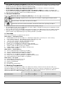
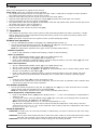
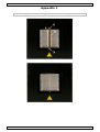
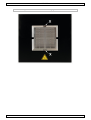
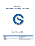
V DIR
VTSD
IN
NFRA-RE
ED SMD & BGA RE
EWORK STATION
S
N
US
SER MANUAL
3 VTSDIR
Main station front panel
Main station rear panel
Figure
21.03.2011
2
©Velleman nv
VTSDIR
Use
er man
nual
1.. Introdu
uction
To
o all residen
nts of the European
E
Un
nion
Im
mportant en
nvironmenttal informattion about this
t
produc
ct
This symbol
s
on th
he device or the package
e indicates th
hat disposal of the devic
ce after its liffecycle could
d
harm the environment. Do no
ot dispose off the unit (orr batteries) as
a unsorted municipal waste;
w
it shou
uld
be tak
ken to a specialized com
mpany for rec
cycling. This device shou
uld be return
ned to your distributor
d
or
to a lo
ocal recycling service. Re
espect the lo
ocal environmental rules
s.
If in doubt,
d
conttact your lo
ocal waste disposal au
uthorities.
Thank you for buying the VTSDIR!
V
Ple
ease read the manual tho
oroughly beffore bringing
g this device into service. If
the
e device was
s damaged in
n transit, do not install orr use it and contact
c
your dealer.
This appliance is specially designed forr SMD/BGA rework and also very co
onvenient forr re-balling smaller
s
BGA
com
mponents.
Ple
ease read this manual ca
arefully to maximize
m
the advantages
s of using yo
our new SMD
D/BGA rework system and
kee
ep this manual readily accessible
a
for reference.
Fo
or more info
o concernin
ng this prod
duct and the latest ver
rsion of this user man
nual, please
e visit our
we
ebsite www
w.velleman.eu.
2.. Safety Instruct
I
ions
: WARNING
W
G and CAU
UTION
: EL
LECTRICA
AL SHOCK
K
Warning and
d Caution arre positioned
d at critical points
p
in the manual to draw
d
the use
er’s attention
n to
significant safety
s
concerrns. Be sure to comply with
w
the follo
owing warnin
ngs and cauttions for you
ur safety.
1. Ensure the voltage rating of the unit
u
and your mains pow
wer supply is identical prior to use.
2. Check carrefully of any
y damage du
uring transpo
ortation.
3. Put the prroducts on a safe and sta
able working
g table. Table surface sh
hould be consisted of fire
e and heat
resistant material
m
due
e to the unit can reach very
v
high tem
mperature an
nd potentiallly dangerous
s.
4. During the
e operation, the heater is extremely
y hot, and wiill cause seriious burns iff contacted exposed
e
skin
n.
Use glove
es and/or any
y heat resisttant tools to pick up the PCB assembly to elimin
nate the poss
sibility of bu
urns.
5. Do not use the produc
ct near comb
bustible gase
es or flammable materia
als.
6. Turn the power
p
switch
h OFF and alllow the heater to cool before
b
checking or replac
cing heater and
a
other pa
arts,
or prior to
o storing the
e unit.
7. Keep the appliance cle
eaning especially the qu
uartz heater. This may be used with a damp clotth using sma
all
amount off liquid detergent. Neverr submerse the
t
unit in liquid or allow
w any liquid to enter the
e station. Never
use any solvent to cle
ean the case.
eater is fragile, be slightlly moving th
he station if necessary.
n
8. Quartz he
9. This unit is
i designed for
f SMD rew
work, BGA re-balling and pre-heating
g PCB assem
mbly and should not be
used for any
a
other purpose without first consulting the manufacturer
m
or its autho
orized agent..
10. Keep the unit out of the reach of children. Young Children
n should be supervised tto ensure tha
at they do not
n
play with the applianc
ce.
o prevent ellectrical shock, be surre to take the followin
ng precautio
ons:
To
1.
2.
3.
4.
5.
6.
7.
Make sure
e the unit is grounded. Always
A
conne
ect power to
o a grounded
d receptacle..
Do not pre
essure the AC
A power corrd. Be sure the
t
work are
ea is well ven
ntilated.
Do not bu
ump, hit, pou
ur water/liqu
uids or otherrwise subjectt the heating
g surface to physical sho
ock. This ma
ay
damage th
he quartz he
eater.
To isolate the equipment from the
e mains befo
ore commencing repairs or making a
any maintenance to avoiid
electric sh
hock. This may
m
result in Death or serious injury.
Do not ex
xpose the unit to moisturre nor use th
he unit with wet hands.
Turn the power
p
switch
h off and rem
move the AC
C power cord
d by pulling the
t
plug (nott the cable) when the un
nit
will remain unused for a longer pe
eriod of time
e.
Do not mo
odify the uniit.
Wa
arnings
•
•
•
This system is design
ned to be used for sold
dering/des
soldering SMDs and should not be used for any
y
other purpo
ose without consulting
c
m
manufacturer
r or its agentts.
The IR han
nd tool is designed for intermitte
ed use only
y. It is not de
esigned to b
be used continuously
without being allowed to
t cool. It sh
hould be used a maximum of 5 minu
utes before c
cooling. After using the IR
I
hand tool, ensure
e
that it is placed back
b
in its co
ooling stand to cool dow
wn between rrework opera
ations. Also, do
not switch the
t
IR Hand tool on whille it is in the
e cooling stand. Fail to comply
c
with there instructions
may resultt in damage
e to the IR hand tool or
o the cooling stand.
Do not aim
m the IR ha
and tool at your
y
eyes. Do not allow
w the IR spott from the IR
R hand tool (either direc
ctly
or via mirro
or) to shine into
i
the eyes
s as serious eye damage
e may occurr.
21.03.2011
3
©Velleman
n nv
VTSDIR
•
•
•
•
The system
m can produce a lot off heat. Do not
n allow the
e IR spot from
m the IR hand tool or IR
R from the PCB
pre-heater, to contact exposed
e
skin
n as burning may occur. To eliminate the possib
bility of burns, allow time
e
for the equipment to co
ool before co
ommencing maintenance
m
e.
Death or serious
s
inju
ury may res
sult from electric shoc
ck. It is there
efore essenttial to isolate
e the
equipment from the ma
ains before commencing
c
repairs.
Do not allo
ow the spillage of any
y liquid to fa
all on the quartz
q
emittter (pre-hea
ater) as dam
mage may
result. Due to the use of
o glass optic
cal compone
ents, the IR hand tool sh
hould be han
ndled with re
easonable care.
Keep this device away from
f
children and unautthorized users.
3.. General Guidelines
Refer to the Ve
elleman® Service
S
and
d Quality Warranty
W
on the last pag
ges of this m
manual.
Indoor use
e only. Keep
p this device away form rain, moisture, splashing
g and dripping liquids.
Keep this de
evice away from
f
dust an
nd extreme heat.
h
Protect this device from shocks and abuse. Avoid brute forc
ce when operating the de
evice.
•
•
•
•
Familiarise yourself with the functio
ons of the de
evice before actually using it.
All modifica
ations of the device are forbidden
f
for safety reas
sons. Damag
ge caused by
y user modiffications to the
t
device is no
ot covered by the warran
nty.
Only use th
he device forr its intended
d purpose. Using
U
the dev
vice in an un
nauthorised way will void
d the warran
nty.
Damage caused by disrregard of cerrtain guidelin
nes in this manual
m
is nott covered by
y the warranty and the
dealer will not
n accept re
esponsibility
y for any ens
suing defects
s or problem
ms.
4.. Overvie
ew
Refer to the illustrations on page 2 of this manual.
Ma
ain station – solderlight section
1.
2.
3.
4.
5.
6.
7.
8.
9.
10.
SOLDERLIIGHT/Timer alternate sw
witch: I = So
olderlight tem
mperature controlled, O = time counting.
Time coun
nting switch:: I = time co
ounting up, O = time co
ounting down
n
“▼” key: Time counting / Actual temperature
e decrease
“▲” key: Time counting / Actual temperature
e increase
ay / IR hand
d tool power
IR Temperature displa
perature in degrees
d
Celsius indicatorr
Celsius (°C): IR Temp
Fahrenheiit (°F): IR Te
emperature in degrees Fahrenheit
F
in
ndicator
“RESET”: Offset forwa
ard counting for “TIMER””
“TIMER” display:
d
Time
e counting display
d
/ Proc
cess timer
“ALARM”: alarm indica
ator
Ma
ain station – Preheat section
s
11.
12.
13.
14.
15.
16.
“▲” key: Temperature
T
e pre-heaterr up (increas
se)
“▼” key: Temperature
T
e pre-heaterr down (decrrease)
“MODEL”: Actual temperature offs
set pre-heatter
Fahrenheiit (°F): Pre-h
heater temperature indic
cating light
Celsius (°C): Pre-heatter temperatture in degre
ees Celsius indicator
i
Preheat te
emperature setting displlay (3 segme
ents)
Ma
ain station - rear pane
el
17.
18.
19.
20.
21.
Solderligh
ht Foot switch socket (4 pin)
DC12V Co
ooling fan so
ocket (3 pin)
Output to PREHEATER
R
Fuse Holder
AC power inlet (Mains
s inlet)
5.. Working Tempe
erature
The most common solderin
ng alloys use
ed in the ele
ectronics industry consist of 60% tin and 40% le
ead. The
operating temp
perature of this
t
type of solder
s
is dettailed below and can varry from manufacturer to manufacturrer.
Ho
owever, to meet
m
RoHS re
equirements, these solde
ers are no lo
onger allowed and are re
eplaced by le
ead-free
sollders that re
equire a work
king tempera
ature which is ±30°C (5
54°F) higher.
Me
elting point
No
ormal Operattion
Pro
oduction Line
e Operation
21.03.2011
lea
aded solder
215
5°C (419°F))
270-320°C (518-60
08°F)
320-380°C (608-71
16°F)
4
lead-free
220°C (428
8°F)
300
0-360°C (572
2-680°F)
360
0-410°C (680
0-770°F)
©Velleman
n nv
VTSDIR
6. Setup
Refer to the illustrations on page 2 of this manual.
Note: never unplug any connection during operation.
• The equipment must be sited on a firm surface at least 1.2M x 0.75M and at a height to suit the operator.
The location should be chosen to suit the flow of work.
• Plug the solder light plug into the socket on the front of the main station.
• Plug the solder light fan into the cooling fan socket [18] and place the solder light in the holder.
• Plug the footswitch into the foot switch socket [17].
• The quartz heaters are secured against shocks with a metal bar and plastic tubes. Remove these and mount
the metal grid in place (refer to Appendix 1).
• Mount the PCB holder (refer to Appendix 2).
• Plug the power cord into the AC power inlet [21].
7. Operation
•
The principle of operation of IR rework system is that whilst being heated from above and below, a single
SMD is subjected to similar temperature/time profile during rework as it experiences during reflow in the
original production process.
Note: wait about 5 minutes for the system to warm up after changing a setting.
IR hand tool operation:
•
•
Set the “SOLDERLIGH/TIMER” switch [1] to the SOLDERLIGHT position (I).
Set the IR Lamp temperature using the “▼” [3] and “▲” [4] keys. Press and hold ±2s to increase
setting speed. Read the temperature on the display [5].
Note: the temperature depends on the type of work (normally about 240°C)
Standard operation
•
Press on the footswitch to start the IR heating; release to stop IR heating.
Timer-up operation
•
•
•
Set the “SOLDERLIGH/TIMER” switch [1] to the TIMER position (O).
Set the “Time counting” switch [2] to the UP position (I).
Press on the footswitch to start IR heating; release to stop IR heating. The timer display [9] will count
the number of seconds that the IR heating was on.
Timer-down operation
•
•
•
Set the “SOLDERLIGH/TIMER” switch [1] to the TIMER position (O).
Set the “Time counting” switch [2] to the DOWN position (O).
Set the timer using the “▼” [3] and “▲” [4] keys. Press and hold ±2s to increase setting speed. Read
the time (in seconds) on the display [9].
• Press on the footswitch to start IR heating; release to stop IR heating. The timer display will count
down the number of seconds that the IR heating was on. When 000 is reached, a warning signal
sounds.
Notes:
• Press the reset switch [8] to return the display to 000.
• To determine the reflow time of a new component, first use the timer up operation until it reflows, than
use the timer value for timer-down operation.
Pre-heater operation:
•
Set the pre-heater temperature using the “▼” [12] and “▲” [11] keys. Press and hold ±2s to increase
setting speed. Read the temperature on the display [16].
Note: the temperature depends on the type of work (normally about 220°C)
Actual temperature compensation value
•
•
Press on the MODEL button [13] until the display shows “---” (±4s). The temperature compensation is
shown for ±2s.
To change the value, press the MODEL button [13] again. The value on the display starts to flash and
can be set using the “▼” [12] and “▲” [11] keys.
Note: when the display shows “00” or “-00” the compensation is “+10”.
E.g. When the temperature is set at 200°C and the measured temperature is only 190°C, then the
value must be set to “00” or “-00”. If the measured value is 180°C, than the compensation value must
be set to “+10” (-20 + 10 = 10).
General operation:
CAUTION: to avoid burns, do not touch the heater or PCB directly, use clips or tweezers to pick up or align
components.
CAUTION: do not allow water/liquids/solvents to touch the heater surface to avoid temperature drop cracks
while the unit is still hot. Such cracks can lead to electrical shorts or failure of the heater.
CAUTION: Do not touch the PCB holder to avoid burning your skin during preheat!
21.03.2011
5
©Velleman nv
VTSDIR
P
Preparation
n
The
•
•
•
The
•
•
•
procedure for preparing to rew
work SMT/BG
GA componen
nts is as follo
ows:
Switch
h on and warrm up.
Set ‘co
ontrol setting
gs’ required for PCB/com
mponent
Sort to
ools and flux
xes required..
followin
ng tools are required forr use in solde
ering/desold
dering operattions:
SMT Tw
weezers, fine tipped
Flux diispenser botttle
Low so
olids and gel/paste flux
T
Temperatur
re profile
In normal operation
o
the
e componentt is first put through a preheat
p
stage
e, followed b
by a reflow stage.
s
The
system is designed for rework single/double sid
de and mixed technology
y PCB. The ttop heat is derived
d
from a
150W shortt wave IR lam
mp focused through a re
eflective cha
amber system
m. The botto
om heater de
elivers a
maximum of
o 650W med
dium wave IR.
I
In normal use,
u
approxim
mately 25% of the energ
gy is proved
d by the top heater, and 75% of the energy is
provided by
y the back heater (pre-h
heater). Figure below sho
ows how the
e energy is a
applied to a component.
c
Soldering
•
PREPARA
ATION: place the PCB in
n the PCB ho
older, positioning the com
mponent site
e to be reworked over th
he
centre of
o the PCB prre-heater. Fo
or BGAs, app
ply a very sm
mall amount of gel flux ((approx. 0.1 - 0.15mm)
thicknes
ss). Place and align comp
ponent. Notte – depending on the ap
pplication, y
you may be required
r
to
apply so
older paste to
o the PCB be
efore placing
g componentt.
o [A] PREHEAT
P
the
e fluxed com
mponent/PCB
B to approxim
mately 120°C
C (as measu
ured by the IR
I sensor).
o [B] REFLOW:
R
use
e the IR han
nd tool (operrated by pressing the foo
otswitch) forr the reflow phase to hea
at
the component up to reflow temperature
t
e (200-225°C
C). It is not so easy to m
measure tem
mperature
durin
ng the reflow
w phase so th
herefore we use the time
er on the IR 810 controller to limit the reflow
phase
e time (norm
mally 30-45 seconds for a small PCB
B).
o [C] SOAK
S
for a short
s
period soak (aboutt 10 seconds
s) the compo
onent allowin
ng the joints
s to fully bon
nd.
o [D] COOL:
C
allow the compon
nent to cool to below 180°C before moving
m
the P
PCB.
Desolderin
ng
•
PREPARA
ATION: place PCB in the
e PCB holderr, positioning
g the compon
nent site to be reworked
d over the
centre of
o the PCB prre-heater. Ap
pply a very small
s
amoun
nt of flux und
der/around tthe compone
ent.
o [A] PREHEAT
P
the
e fluxed com
mponent/PCB
B to approxim
mately 120°C
C (as measu
ured by the IR
I sensor).
o [B] REFLOW:
R
use
e the IR han
nd tool (operrated by pressing the foo
otswitch) forr the reflow phase to hea
at
the component up to reflow temperature
t
e (200-225°C
C). It is not so easy to m
measure tem
mperature
durin
ng the reflow
w phase so th
herefore we use the time
er on the IR8
810 controlle
er to limit th
he reflow pha
ase
time (normally 30-45 second
ds for a smalll PCB).
o [C] SOAK
S
for a short
s
period soak (aboutt 10 seconds
s) the compo
onent allowin
ng the joints
s to fully bon
nd.
o [D] COOL
C
– allow
w the compo
onent to cool to below 18
80°C before moving the PCB.
Aftercare
•
•
•
ux residue offf PCB if nec
cessary
Clean flu
Check so
older joints
Test
8.. Q&A
•
•
•
What Top Heat
H
setting should you use?
u
Between
n 220 and 38
80°C. Norma
al setting is 240°C.
What’s the working disttance of the IR Hand too
ol and how do
d I move it for rework?
Approxim
mately 5~10
0 mm when reworking and move up to 30mm when
w
removin
ng components.
Move the hand tool in a scanning motion to heat leads, taking abou
ut one second for each sc
can of the
compone
ent.
What pre-heater setting
g should I us
se?
Between
n 200 and 29
90°C. Norma
al setting is 240°C.
21.03.2011
6
©Velleman
n nv
VTSDIR
•
•
How long do I preheat the PCB?
Always preheat the PCB (up to 120°C or between 45 – 90 seconds) to allow the heat to conduct through
to the component before introducing the top heat. With the 700W pre-heater the top of a small PCB will
reach 120°C in approximately 45 – 90 seconds. Larger PCBs will take longer to pre-heat. To check the
PCB/component temperature, use the hand-held IR temperature sensor to ‘look’ down at the
PCB/component from about 60mm away and at about 45° angle.
How long does it take to reach reflow temperature?
After preheating the PCB up to 120°C, it should normally take about 30 – 45 seconds of heating with the
IR hand tool to reach reflow temperature (200-220°C). It is not so easy to measure temperature during
the reflow phase so therefore we use the electronic process timer to warn us when the reflow phase time
is over.
9. Technical specifications
mains power
IR solderlight
pre-heater
dimensions
230VAC
150W
45 ~ 350°C
0 ~ 900s
650W
100 ~ 350°C
170 x 158 x 137 mm
280 x 90 x 260 mm
±7kg
power
temperature range
time setting
power
temperature range
controller
pre-heater
weight
Use this device with original accessories only. Velleman nv cannot be held responsible in the event
of damage or injury resulted from (incorrect) use of this device.
The information in this manual is subject to change without prior notice.
© COPYRIGHT NOTICE
The copyright to this manual is owned by Velleman nv. All worldwide rights reserved.
No part of this manual or may be copied, reproduced, translated or reduced to any electronic medium or otherwise without
the prior written consent of the copyright holder.
21.03.2011
7
©Velleman nv
VTSDIR
Appendix 1
Remove screws [X], remove metal bar [Y] and remove plastic tubes [Z].
21.03.2011
8
©Velleman nv
VTSDIR
Place the metal grid and secure it with the two screws [X].
21.03.2011
9
©Velleman nv
VTSDIR
Appendix 2
21.03.2011
10
©Velleman nv
VTSDIR
21.03.2011
11
©Velleman nv
Velleman® Service and Quality Warranty
Velleman® has over 35 years of experience in the electronics
world and distributes its products in more than 85 countries.
All our products fulfil strict quality requirements and legal
stipulations in the EU. In order to ensure the quality, our
products regularly go through an extra quality check, both by
an internal quality department and by specialized external
organisations. If, all precautionary measures
notwithstanding, problems should occur, please make appeal
to our warranty (see guarantee conditions).
General Warranty Conditions Concerning Consumer
Products (for EU):
• All consumer products are subject to a 24-month warranty
on production flaws and defective material as from the
original date of purchase.
• Velleman® can decide to replace an article with an
equivalent article, or to refund the retail value totally or
partially when the complaint is valid and a free repair or
replacement of the article is impossible, or if the expenses
are out of proportion.
You will be delivered a replacing article or a refund at the
value of 100% of the purchase price in case of a flaw
occurred in the first year after the date of purchase and
delivery, or a replacing article at 50% of the purchase price
or a refund at the value of 50% of the retail value in case of
a flaw occurred in the second year after the date of purchase
and delivery.
• Not covered by warranty:
- all direct or indirect damage caused after delivery to the
article (e.g. by oxidation, shocks, falls, dust, dirt,
humidity...), and by the article, as well as its contents (e.g.
data loss), compensation for loss of profits;
- frequently replaced consumable goods, parts or accessories
such as batteries, lamps, rubber parts, drive belts...
(unlimited list);
- flaws resulting from fire, water damage, lightning, accident,
natural disaster, etc. …;
- flaws caused deliberately, negligently or resulting from
improper handling, negligent maintenance, abusive use or
use contrary to the manufacturer’s instructions;
- damage caused by a commercial, professional or collective
use of the article (the warranty validity will be reduced to six
(6) months when the article is used professionally);
- damage resulting from an inappropriate packing and
shipping of the article;
- all damage caused by modification, repair or alteration
performed by a third party without written permission by
Velleman®.
• Articles to be repaired must be delivered to your
Velleman® dealer, solidly packed (preferably in the original
packaging), and be completed with the original receipt of
purchase and a clear flaw description.
• Hint: In order to save on cost and time, please reread the
manual and check if the flaw is caused by obvious causes
prior to presenting the article for repair. Note that returning
a non-defective article can also involve handling costs.
• Repairs occurring after warranty expiration are subject to
shipping costs.
• The above conditions are without prejudice to all
commercial warranties.
The above enumeration is subject to modification
according to the article (see article’s manual).