1
General
Specifications
GS 04L53B00-01EN
GX60
I/O Base Unit (Expandable I/O)
GX90EX
Expansion Module
OVERVIEW
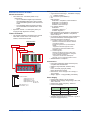
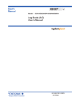
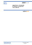
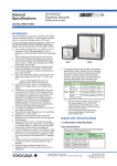
GX60 I/O Base Unit (Expandable I/O)
The GX60 provides a function to expand an I/O
module for recording and controlling, when it is
connected to the expansion module that is connected
to the GX10/GX20/GP10/GP20 using a LAN cable via
a private communication network.
● One GX60 can connect up to six I/O modules.
● Up to six units can be additionally connected to
the GX/GP.
● The communication distance between the
GX/GP and GX60 or between GX60s can be
extended by up to 100 m using a LAN cable.
Power Screw type
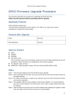
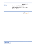
GX90EX Expansion Module
The expansion module is connected to the GX10/
GX20/GP10/GP20, GX60, GM main unit, and GM sub
unit.
[If GX90EX expansion module is connected to the GX/
GP or I/O base unit]
● The expansion module, which is supported by
the GX/GP and GX60, enables a connection
between GX/GP and GX60 or a communication
between GX60s.
● A distributed arrangement with the data
time synchronization secured is provided by
connecting Expansion modules connected to the
GX/GP main unit and GX60 using a LAN cable.
● Data is transferred to the high-order GX/GP via
the expansion module.
[If GX90EX expansion module is connected to the GM
main unit/sub unit]
● The expansion module, which is supported
by the GM main unit and sub unit, enables a
connection between GM main unit and sub unit
or a communication between sub units.
● A distributed arrangement with the data
time synchronization secured is provided by
connecting Expansion modules connected to the
GM main unit and sub unit using a LAN cable.
● Data is transferred to the high-order GM10 via
the expansion module.
GX60
Power inlet type
GX90EX
Yokogawa Electric Corporation
2-9-32, Nakacho, Musashino-shi, Tokyo, 180-8750 Japan
GS 04L53B00-01EN
©Copyright April 2014
3rd Edition Oct. 27, 2014
2
GX60 SPECIFICATIONS
Module Connection
• I/O module: Max. 6 modules (Slots 0 to 5)
Restrictions:
• Up to 10 GX90YD digital output modules
and GX90WD digital input/output modules
can be installed together in the GX/GP and
GX60.
• One GX90WD digital input/output module
can be installed in the GX/GP and in each
GX60.
• Expansion module: 1 module (Slot ("EXT") for
connection with Expansion module)
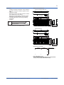
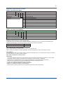
Names of Channels
• The module installed in the GX60 has a channel
name that consists of the unit number, slot
number, and channel number.
Channel name
Unit number
Slot number
Channel number
I/O modules
Safety and EMC Standards
• CSA: CSA22.2 No.61010-1, installation category
II *1, pollution degree 2 *2
• UL: UL61010-1 (CSA NRTL/C)
• CE:
EMC directive
EN61326-1 compliance, Class A Table 2
EN61000-3-2 compliance
EN61000-3-3 compliance
EN55011 Class A Group 1
Low voltage directive
EN61010-1
Installation category II *1
Pollution degree 2 *2
• EMC Regulatory Arrangement in Australia and
New Zealand (RCM): EN55011 compliance,
Class A Group 1
• KC marking: Electromagnetic wave interference
prevention standard, electromagnetic wave
protection standard compliance
*1 Installation category (overvoltage category) II:
Describes a number which defines a transient
overvoltage condition.
Implies the regulation for impulse withstand
voltage.
“II” applies to electrical equipment which
is supplied from the fixed installation like a
distribution board.
*2 Pollution degree 2:
Describes the degree to which a solid, liquid,
or gas which deteriorates dielectric strength or
surface resistivity is adhering.
“2” applies to normal indoor atmosphere.
Normally, only non-conductive pollution occurs.
• WEEE Directive: Compliant
Construction
5 4 3 2 1 0
Channel number;
Analog input: 01 to 10
Digital input: 01 to 16
Digital output: 01 to 06
Digital input/output: DI 01 to 08
DO 09 to 14
Slot number; 0 to 5
Unit number; 1 to 6
• Front panel (terminal): Water and dust-proof,
Complies with IEC529-IP20
• Material: Polycarbonate, aluminum alloy
•Color;
Front: Charcoal grey light (CC28)
Bezel: Smoke blue (CC53)
• Dimensions: 412.5 mm(W) x 164.7 mm(H) x
127.8 mm(D)
• Weight: Approx. 3.2 kg (installing 6 modules)
Power Supply
• Rated supply voltage: 100 to 240 VAC
• Allowable power supply voltage range: 90 to 132,
180 to 264 VAC
• Rated power supply frequency: 50/60 Hz
• Power consumption:
Supply voltage
*
Normal
operation *
Maximum
100 V AC
20 VA
40 VA
240 V AC
30 VA
55 VA
When using 6 analog input modules.
• Allowable interruption time: Less than 1 cycle of
the power supply frequency
All Rights Reserved. Copyright © 2014, Yokogawa Electric Corporation
GS 04L53B00-01EN
Oct. 27, 2014-00
3
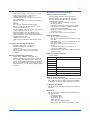
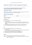
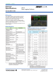
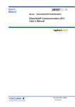
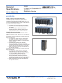
External Dimensions
412.5 (16.2)
156 (6.14)
162 (6.38)
48
6-Φ5 hole
(6-Φ0.2) hole
(1.89)
Input and output module terminal
Input and output module internal circuit
Earth (PE) terminal
Internal circuit
8.7
(0.34)
Power
terminal
Power screw terminal type
148 (5.83)
• Insulation resistance: Between each insulation
terminals, and earth: 20 MΩ or greater at 500
VDC
• Withstand voltage:
Between the power terminal and earth: 3000 V
AC at 50/60 Hz for one minute
Between the input/output modules and earth:
Depends on the specification of I/O module.
• Grounding: Be sure to set a low grounding
resistance.
• Isolation:
164.7 (6.48)
Isolation
The circuits divided by lines are insulated mutually.
127.8 (5.03)
Power inlet type
6-Φ5 hole
(6-Φ0.2) hole
156±0.2
(6.14±0.0078)
162±0.2
(6.38±0.0078)
127.8 (5.03)
6-Φ4.5 hole or M4
(0.24-Φ0.18) hole or M4
148±0.4
(5.83±0.0157)
Dimensions of fixing hole
8.7
(0.34)
148 (5.83)
(1.89)
412.5 (16.2)
156 (6.14)
162 (6.38)
164.7 (6.48)
48
Unit: mm (approx. inch)
Unless otherwise specified, tolerance is ±3% (however,
tolerance is ±0.3 mm when below 10 mm).
All Rights Reserved. Copyright © 2014, Yokogawa Electric Corporation
GS 04L53B00-01EN
Oct. 27, 2014-00
4
Normal Operating Conditions
•
•
•
•
•
•
•
•
•
•
•
Power supply voltage: 100 to 240 V AC ±10 %
Power supply frequency: 50/60 Hz ±2 %
Ambient temperature: 0 to 50 °C
Ambient humidity: 20 to 80 %RH (at 5 to 40°C)
(no condensation)
Magnetic field: 400 A/m or less (DC and 50/60
Hz)
Vibration:
5 ≤ f < 8.4 Hz amplitude 3.5 mm (peak)
8.4 ≤ f ≤ 160 Hz acceleration 9.8 m/s2 or less
Shock (IEC-60068-2-27):
Non-energization, 500 m/s2 or less, approximate
10 ms, 6 directions (±X, ±Y, ±Z)
Mounting position: Can be inclined up to 30
degrees backward. Left and right horizontal
when installing the panel mount and wall mount.
Altitude: 2000 m or less
Installation location: Indoors
Warm-up time: At least 30 minutes after power
on
GX90EX SPECIFICATIONS
Communication Functions
*1 Can be fixed to 10Base-T by DIP switch settings.
Display Functions
• System status LED indicators:
RDY (green): Lights up when the CPU is running
normally.
MASTER (green): Turns on in master mode and
off in slave mode.
FAIL (red): Lights up when a system error
occurs.
• 7-segment LED indicator: Indicates a unit
number or operation error.
• Ethernet status indicator LED: LINK ACT (green),
SPEED (orange)
Transport and Storage Conditions
• Ambient temperature: –25 to 60°C
• Ambient humidity: 5 to 95 %RH (no
condensation)
• Vibration: 10 to 60 Hz, 4.9 m/s2 maximum
• Shock: 392 m/s2 maximum (in packaged
condition)
Effects of Operating Conditions
• Power supply variation: Shall satisfy the
accuracy specification in the range of 90 to 132
VAC or 180 to 250 VAC (frequency: 50/60 Hz).
Power supply frequency fluctuation: Shall satisfy
the accuracy specification in the range of rated
supply frequency +/-2 Hz (power-supply voltage:
100 VAC).
Communication between GX/GP and GX60,
between GX60s, between GM main unit and
sub unit, between GM sub units via dedicated
communication network.
• Baud rate: 10Base-T/100Base-TX (Auto) *1
• Number of ports: 2
• Connection cable: STP cable, CAT5 or greater
• Inter-module connection: Cascade connection
(Ring connection is disabled.)
• Maximum communication distance: 100 m
• Connector: RJ-45
Address Setting Functions
Switch settings:
Switch No.
Descriptions
1
For unit number setting
2
3
4
5
-
6
-
7
10 Mpbs/100 Mbps switching
8
MASTER/SLAVE switching
Master / Slave Functions
Can be set to master mode (when installed in the GX/
GP or GM main unit), or slave mode (when installed
in the GX60 or GM sub unit) using the DIP switches.
10 Mbps Fixed Mode
Can be set to the 10 Mbps fixed mode using the DIP
switches.
Mounting
Can be mounted in the GX/GP, GX60, GM main unit,
and GM sub unit.
• Mounting position:
GX10/GP10: Slot 2
GX20/GP20: Slot 9
GX60: EXT slot
GM main unit: Leftmost position
GM sub unit: Next to the power supply module
All Rights Reserved. Copyright © 2014, Yokogawa Electric Corporation
GS 04L53B00-01EN
Oct. 27, 2014-00
5
• WEEE Directive: Compliant
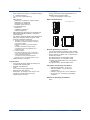
Construction
• Front panel (terminal): Water and dust-proof,
Complies with IEC529-IP20
• Material: Polycarbonate
•Color;
Front: Charcoal grey light (CC28)
Bezel: Smoke blue (CC53)
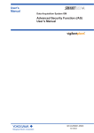
• Dimensions: 45 mm(W) x 100 mm(H) x 133
mm(D) (D: including terminal cover)
• Weight: Approx. 0.18 kg
Suppy from GX/GP, GX60 expandable I/O, or
GM90PS power supply module.
• Power consumption:1.8W or less
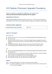
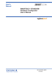
External Dimensions
Unit: mm (approx. inch)
3(0.12)
31.9
100(3.94)
45.1(1.78)
8(0.31)
*1 Installation category (overvoltage category) II:
Describes a number which defines a transient
overvoltage condition.
Implies the regulation for impulse withstand
voltage.
“II” applies to electrical equipment which
is supplied from the fixed installation like a
distribution board.
*2 Pollution degree 2:
Describes the degree to which a solid, liquid,
or gas which deteriorates dielectric strength or
surface resistivity is adhering.
“2” applies to normal indoor atmosphere.
Normally, only non-conductive pollution occurs.
Power Supply
107.1
• CSA: CSA22.2 No.61010-1, installation category
II *1, pollution degree 2 *2
• UL: UL61010-1 (CSA NRTL/C)
• CE:
EMC directive
EN61326-1 compliance, Class A Table 2
EN61000-3-2 compliance
EN61000-3-3 compliance
EN55011 Class A Group 1
Low voltage directive
EN61010-1
Installation category II *1
Pollution degree 2 *2
• EMC Regulatory Arrangement in Australia and
New Zealand (RCM): EN55011 compliance,
Class A Group 1
• KC marking: Electromagnetic wave interference
prevention standard, electromagnetic wave
protection standard compliance
82.1(3.23)
Safety and EMC Standards
Normal Operating Conditions
For normal operating conditions of this module,
please refer to the General Specifications of the
device (GX/GP, I/O Base Unit, or GM) that this
module is mounted.
GX Specifications: GS 04L51B01-01EN
GP Specifications; GS 04L52B01-01EN
I/O Base Unit (Expandable I/O): This General
Specifications
GM Specifications: GS 04L55B01-01EN
Transport and Storage Conditions
• Ambient temperature: –25 to 70°C
• Ambient humidity: 5 to 95 %RH (no
condensation)
• Vibration: 10 to 60 Hz, 4.9 m/s2 maximum
• Shock: 392 m/s2 maximum (in packaged
condition)
Effects of Operating Conditions
None
All Rights Reserved. Copyright © 2014, Yokogawa Electric Corporation
GS 04L53B00-01EN
Oct. 27, 2014-00
6
MODEL AND SUFFIX CODES
MODEL and SUFFIX Code (GX60)
Model
Suffix Code
Description
GX60
I/O Base Unit
-EX
Type
I/O Expansion
N
Area
General
1
Power supply
100 V AC, 240 V AC
Power cord
D
Power cord UL/CSA standard
F
Power cord VDE standard
R
Power cord AS standard
Q
Power cord BS standard
H
Power cord GB standard
N
Power cord NBR standard
W
Screw terminal (M3)
*One GX90EX (I/O expansion module) is provided.
MODEL and SUFFIX Code (GX90EX)
Model
Suffix Code
Description
GX90EX
Port
I/O Expansion Module
-02
2 ports
-TP1
Type
Twisted Pair Cable
N
-
Always N
-N
Area
General
Optional Accessories (Sold Separately)
The dummy cover is for empty slots on GX/GP and GX60. The dummy cover is not attached to the GX60 when
shipped from the factory. If you need the dummy cover, please purchase it separately.
Product
Dummy cover
Part no.
B8740CZ
Test certificate (QIC, sold separately)
When ordering the GX60, GX90EX gets its own QIC (one QIC per unit).
When ordering the expansion modules separately, each module gets its own QIC (one QIC per module).
User's Manual
Product user's manuals can be downloaded or viewed at the following URL. To view the user's manual, you need to
use Adobe Reader 7 or later by Adobe Systems.
URL: www.smartdacplus.com/manual/en/
Trademarks
The TCP/IP software used in this product and the document for that TCP/IP software are based in part on BSD
networking software, Release 1 licensed from The Regents of the University of California.
•SMARTDAC+ and SMARTDACPLUS are registered trademarks of Yokogawa Electric Corporation.
•Microsoft, MS and Windows are registered trademarks of Microsoft Corporation USA.
•Pentium are registered trademarks of Intel Corporation.
•Ethernet is a registered trademark of XEROX Corporation.
Modbus is a registered trademark of AEG Schneider.
•Other company and/or product names are registered trade mark of their manufactures.
All Rights Reserved. Copyright © 2014, Yokogawa Electric Corporation
GS 04L53B00-01EN
Oct. 27, 2014-00