1
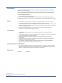
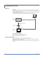
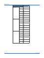
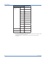
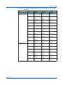
User’s
Manual
Model
GX10/GP10/GX20/GP20
EtherNet/IP Communication (/E1)
User’s Manual
IM 04L51B01-18EN
1st Edition
Introduction
Notes
Trademarks
Thank you for purchasing the SMARTDAC+ Series GX10/GX20/GP10/GP20 (hereafter
referred to as the GX or GP).
This manual explains the EtherNet/IP communication function (/E1 option) of the GX/GP.
In this manual, the GX20/GP20 standard type and large memory type are distinguished
using the following notations.
• Standard type: GX20-1/GP20-1
• Large memory type: GX20-2/GP20-2
To ensure correct use, please read this manual thoroughly before beginning operation.
Please use this manual in conjunction with the GX/GP User’s Manual (IM 04L51B01-01EN)
• The contents of this manual are subject to change without prior notice as a result of
continuing improvements to the instrument’s performance and functions.
• Every effort has been made in the preparation of this manual to ensure the accuracy of its
contents. However, should you have any questions or find any errors, please contact your
nearest YOKOGAWA dealer.
• Copying or reproducing all or any part of the contents of this manual without the
permission of YOKOGAWA is strictly prohibited.
• vigilantplant and SMARTDAC+ are registered trademarks of Yokogawa Electric
Corporation.
• Microsoft and Windows are registered trademarks or trademarks of Microsoft Corporation
in the United States and/or other countries.
• Adobe and Acrobat are registered trademarks or trademarks of Adobe Systems
Incorporated.
• Company and product names that appear in this manual are registered trademarks or
trademarks of their respective holders.
• The company and product names used in this manual are not accompanied by the
registered trademark or trademark symbols (® and ™).
Using Open Source Software
• The TCP/IP software of this product and the document concerning the TCP/IP software
have been developed/created by YOKOGAWA based on the BSD Networking Software,
Release 1 that has been licensed from University of California.
Revisions
May 2014
1st Edition
1st Edition: May 2014 (YK)
All Right Reserved, Copyright © 2014, Yokogawa Electric Corporation
IM 04L51B01-18EN
i
Conventions Used in This Manual
Unit
K
k
Markings
WARNING
CAUTION
Note
Reference Item
Denotes 1024. Example: 768K (file size)
Denotes 1000.
Improper handling or use can lead to injury to the user or damage to
the instrument. This symbol appears on the instrument to indicate that
the user must refer to the user’s manual for special instructions. The
same symbol appears in the corresponding place in the user’s manual
to identify those instructions. In the manual, the symbol is used in
conjunction with the word “WARNING” or “CAUTION.”
Calls attention to actions or conditions that could cause serious or fatal
injury to the user, and precautions that can be taken to prevent such
occurrences.
Calls attention to actions or conditions that could cause light injury
to the user or cause damage to the instrument or user’s data, and
precautions that can be taken to prevent such occurrences.
Calls attention to information that is important for the proper operation
of the instrument.
Reference to related operation or explanation is indicated after this
mark.
Example: section 4.1
Conventions Used in the Procedural Explanations
Bold characters Denotes key or character strings that appear on the screen.
Example: Volt
Indicates the character types that can be used.
Aa#1
A
1
Procedure
Explanation
Path
uppercase alphabet, numbers a
lowercase alphabet,
#
symbol,
Carry out the procedure according to the step numbers. All procedures
are written with inexperienced users in mind; depending on the
operation, not all steps need to be taken.
Explanation gives information such as limitations related the procedure.
Indicates the setup screen and explains the settings.
Description
ii
IM 04L51B01-18EN
Assumption of Explanation
The explanation in this manual assumes that the GX/GP is connected via communications
with Rockwell Automation’s Programmable Logic Controller (PLC) of the Allen-Bradley
brand.The basic items for this configuration are explained. For the operation procedures of
Rockwell Automation products, see the user’s manuals of these products.
This manual is intended for those who have used an Allen-Bradley PLC and EtherNet/IP.
GX/GP Version Described in This Manual
The contents of this manual correspond to the GX/GP with release number 2 (see the
STYLE S number) and style number 1 (see the STYLE H number).
IM 04L51B01-18EN
iii
Contents
Introduction................................................................................................................................................. i
Conventions Used in This Manual............................................................................................................. ii
Assumption of Explanation........................................................................................................................iii
GX/GP Version Described in This Manual.................................................................................................iii
Introduction of Features........................................................................................................................ 1
EtherNet/IP................................................................................................................................................ 1
What the GX/GP Can Do........................................................................................................................... 2
Settings of the GX/GP............................................................................................................................... 2
Access to the GX/GP................................................................................................................................. 2
Connection to a Network...................................................................................................................... 3
Cable Connection...................................................................................................................................... 3
Settings of the GX/GP............................................................................................................................... 3
Preparation for PLC.............................................................................................................................. 4
EDS File4
System Configuration................................................................................................................................ 4
Explicit Message................................................................................................................................... 5
System Configuration on PLC................................................................................................................... 5
Data on the GX/GP.................................................................................................................................. 16
I/O Messages...................................................................................................................................... 17
System Configuration on PLC................................................................................................................. 17
Data on the GX/GP.................................................................................................................................. 20
Communication Considerations.......................................................................................................... 21
About Communication Interval................................................................................................................ 21
Access to Non-existent Data................................................................................................................... 21
Special data............................................................................................................................................. 21
Writing Data to the GX/GP...................................................................................................................... 21
Specifications...................................................................................................................................... 22
Example of an Explicit Message Using RSLogix 5000....................................................................... 23
Example of I/O Message Using RSLogix 5000................................................................................... 25
iv
IM 04L51B01-18EN
Introduction of Features
EtherNet/IP
EtherNet/IP is a protocol that extends Common Industrial Protocol (CIP) to Ethernet.
The use of Ethernet enables high-speed and periodic exchange of massive control and
monitoring data between control devices placed at dispersed locations.
Devices that support EtherNet/IP are available from many vendors. Among them, Rockwell
Automation’s Programmable Logic Controller (PLC) and Remote I/O of the Allen-Bradley
brand are widely used. Yokogawa’s GX/GP, equipped with the EtherNet/IP server function,
supports communications with these PLCs.
Configuration Components
• Scanner (Client)
A device that launches a request on EtherNet/IP. This is either a PLC or PC. For the GX/
GP, PLCs such as Allen-Bradley PLC-2, PLC-5, SLC 500, MicroLogix, CompactLogix,
and ControlLogix represent a Scanner (Client).
• Adapter (Server)
A remote I/O device that the Scanner (Client) can access to read or write data. The GX/
GP is an Adapter (Server).
• Configuration tool
A tool used to configure the system. This is either a PC on which configuration software
has been installed or the software itself. Rockwell Automation RSLogix500 and
RSLogix5000 and the communication driver software RSLinx are configuration tools.
Configuration tool
Scanner
(Client)
Ethernet
EtherNet/IP
Adapter
(Server)
Remote I/O
GX/GP
Note
For details of EtherNet/IP, see the information supplied by the Open DeviceNet Vender Association
(ODVA).
IM 04L51B01-18EN
1
Introduction of Features
What the GX/GP Can Do
The GX/GP provides the following functions:
• Participate in an EtherNet/IP network as an Adapter (Server).
• Communicate with new and old Allen-Bradley PLCs such as MicroLogix, CompactLogix,
ControlLogix, SLC 500, PLC-5, and PLC-2.
• Support both Explicit and I/O messages.
• PLCs can access internal data of the GX/GP.
Data
Input/Output channel data
Computation channel1 data
Communication channel2 data
Access
Read
Read
Read/write
1 Option (/MT)
2 Option (/MC)
The following shows examples of usage.
• Data on devices on a network can be recorded by a PLC to the GX/GP.
• Data measured by the GX/GP can be acquired by a PLC.
Settings of the GX/GP
The GX/GP is ready to use after the following settings have been made.
• IP address and other settings required to connect to Ethernet
• Enabling of EtherNet/IP server function
Access to the GX/GP
The GX/GP is a passive device on an Ethernet network. The GX/GP cannot launch a
request. A PLC launches a request to the GX/GP.
A request is called a “message”. There are two message types: Explicit message and
I/O messages (Implicit message). An Explicit message, included in control logic, is used
to access the GX/GP, only when required, and transmit data. An I/O message is used to
transmit pre-specified GX/GP data at intervals.
The GX/GP can also communicate with PLCs compatible with Programmable Controller
Communication Command (PCCC) using conversion of PCCC to EtherNet/IP at the
gateway. PCCC refers to serial communications that are also called DF1 communications.
The GX/GP supports EtherNet/IP in which PCCC requests are encapsulated. It can
communicate also with PLCs that support encapsulated PCCC.
2
IM 04L51B01-18EN
Connection to a Network
Cable Connection
Connect the Ethernet cable to the Ethernet port provided on the back of the GX/GP.
CAUTION
Be sure to connect an Ethernet cable
with an FCC-compliant plug. Otherwise,
the GX/GP may malfunction.
Ethernet port
Settings of the GX/GP
IP Address, Host Information, and DNS Setting, etc.
See User’s manual (IM 04L51B01-01EN) section 1.16 Configuring the Ethernet
Communication Function.
EtherNet/IP Server Settings
Path
GX/GP: MENU key > Browse tab > Setting > Setting menu Communication (Ethernet)
settings > Server settings > Server list
Web browser: Config. tab > Communication (Ethernet) settings > Server list
Hardware configurator: Communication (Ethernet) settings > Server list
Description
EtherNet/IP
Setup Item
On/Off
Selectable Range or Options
Off, On
Default Value
Off
On/Off
Specify On to enable the EtherNet/IP server.
Note
The EtherNet/IP server settings can be checked on the Network Information Screen of the GX/GP.
You can open the Network Information Screen by pressing the MENU key, tap the Browse tab >
Network information.
IM 04L51B01-18EN
3
Preparation for PLC
EDS File
Installation
To have the GX/GP participate in a network, first install the GX/GP device profile (Electronic
Data Sheet; EDS file) in the configuration tool. A PLC communicates with the GX/GP based
on the information in the EDS file.
Conduct installation using the “EDS Hardware Installation Tool” of RSLinx. For information
on using the configuration tool, see the user’s manual of the configuration tool.
Configuration tool
Scanner
(Client)
PLC
Read/Write message
EtherNet/IP
Ethernet
EDS file
Adapter
(Server)
GX/GP
How to Obtain the EDS File
Obtain the EDS file from the Yokogawa Web site:
URL: www.smartdacplus.com/software/en/
System Configuration
Use the configuration tool to make the communication settings.
Use RSLinx, RSLogix500, or RSLogix5000 to make an Explicit message or I/O message,
download it to the PLC, and execute it.
For information on using the configuration tool and a PLC, see the user’s manuals of these
products.
4
IM 04L51B01-18EN
Explicit Message
An Explicit message is a point-to-point, request/response-type communication.
System Configuration on PLC
Use the configuration tool to code an Explicit message as an MSG instruction in the
control logic. In the MSG instruction, set all the information including a target device,
target register, and read/write. Download the created control logic to a PLC and execute
it.
On the GX/GP, the data count to be accessed per MSG instruction should be 100 or less.
In Case of PLC-2, PLC-5, and SLC
• Commands
When creating an MSG instruction, specify a command. The GX/GP supports the
following commands:
Target PLC
PLC-2
PLC-5
Command name
PLC2 Unprotected Read/Write
PLC5 Word Range Read/Write
PLC5 Typed Read/Write
SLC Typed Read/Write
SLC
• Specification of data to be accessed
Specify which of the data in the GX/GP should be accessed. The PLC-2, PLC-5, and SLC
manage data to be accessed in units of “files.”
Command: PLC2 Unprotected Read/Write
Data to be accessed
Type
Input/Output channel
(GX/GP main unit)
IM 04L51B01-18EN
Number
0001
•••
0050
0101
•••
0150
0201
•••
0250
0301
•••
0350
0401
•••
0450
0501
•••
0550
0601
•••
0650
0701
•••
0750
0801
•••
0850
0901
•••
0950
File number
Data type: INT16
1000
•••
1049
1050
•••
1099
1100
•••
1149
1150
•••
1199
1200
•••
1249
1250
•••
1299
1300
•••
1349
1350
•••
1399
1400
•••
1449
1450
•••
1499
Continued on next page
5
Explicit Message
Data to be accessed
Type
Input/Output channel
Expandable I/O 1
(Expandable I/O 2)
(Expandable I/O 3)
6
Number
1001
•••
1050
1101
•••
1150
1201
•••
1250
1301
•••
1350
1401
•••
1450
1501
•••
1550
2001
•••
2050
2101
•••
2150
2201
•••
2250
2301
•••
2350
2401
•••
2450
2501
•••
2550
3001
•••
3050
3101
•••
3150
3201
•••
3250
3301
•••
3350
3401
•••
3450
3501
•••
3550
File number
Data type: INT16
1500
•••
1549
1550
•••
1599
1600
•••
1649
1650
•••
1699
1700
•••
1749
1750
•••
1799
2000
•••
2049
2050
•••
2099
2100
•••
2149
2150
•••
2199
2200
•••
2249
2250
•••
2299
2500
•••
2549
2550
•••
2599
2600
•••
2649
2650
•••
2699
2700
•••
2749
2750
•••
2799
Continued on next page
IM 04L51B01-18EN
Explicit Message
Data to be accessed
Type
Input/Output channel
(Expandable I/O 4)
(Expandable I/O 5)
(Expandable I/O 6)
IM 04L51B01-18EN
Number
4001
•••
4050
4101
•••
4150
4201
•••
4250
4301
•••
4350
4401
•••
4450
4501
•••
4550
5001
•••
5050
5101
•••
5150
5201
•••
5250
5301
•••
5350
5401
•••
5450
5501
•••
5550
6001
•••
6050
6101
•••
6150
6201
•••
6250
6301
•••
6350
6401
•••
6450
6501
•••
6550
File number
Data type: INT16
3000
•••
3049
3050
•••
3099
3100
•••
3149
3150
•••
3199
3200
•••
3249
3250
•••
3299
3500
•••
3549
3550
•••
3599
3600
•••
3649
3650
•••
3699
3700
•••
3749
3750
•••
3799
4000
•••
4049
4050
•••
4099
4100
•••
4149
4150
•••
4199
4200
•••
4249
4250
•••
4299
Continued on next page
7
Explicit Message
Data to be accessed
Type
Input/Output channel
(Continuous channel
data area)*
File number
Data type: INT16
Number
0001
4500
•••
•••
0010
4509
0101
4510
•••
•••
0110
4519
0201
4520
•••
•••
0210
4529
0301
4530
•••
•••
0310
4539
0401
4540
•••
•••
0410
4549
0501
4550
•••
•••
0510
4559
0601
4560
•••
•••
0610
4569
0701
4570
•••
•••
0710
4579
0801
4580
•••
•••
0810
4589
0901
4590
•••
•••
0910
4599
Computation channel A001
5000
•••
•••
A100
5099
Communication
C001
6000
channel (Read/Write) • • •
•••
C500
6499
“• • •” stands for data in numerical order.
* The “continuous channel data area” is a special area that enables continuous reading by limiting
the number of channels of each module to 10.
For the I/O channels only on the GX/GP main unit, this area can be used to read data
consecutively.
8
IM 04L51B01-18EN
Explicit Message
Commands: PLC5 Word Range Read/Write, PLC5 Typed Read/Write, and SLC Typed
Read/Write
Data to be accessed
Type
Input/Output channel
(GX/GP main unit)
(Expandable I/O 1)
IM 04L51B01-18EN
Number
0001
•••
0050
0101
•••
0150
0201
•••
0250
0301
•••
0350
0401
•••
0450
0501
•••
0550
0601
•••
0650
0701
•••
0750
0801
•••
0850
0901
•••
0950
1001
•••
1050
1101
•••
1150
1201
•••
1250
1301
•••
1350
1401
•••
1450
1501
•••
1550
File number
Data type
INT16
N10:00
•••
N10:49
N10:50
•••
N10:99
N11:00
•••
N11:49
N11:50
•••
N11:99
N12:00
•••
N12:49
N12:50
•••
N12:99
N13:00
•••
N13:49
N13:50
•••
N13:99
N14:00
•••
N14:49
N14:50
•••
N14:99
N15:00
•••
N15:49
N15:50
•••
N15:99
N16:00
•••
N16:49
N16:50
•••
N16:99
N17:00
•••
N17:49
N17:50
•••
N17:99
Data type
INT32
L10:00
•••
L10:49
L10:50
•••
L10:99
L11:00
•••
L11:49
L11:50
•••
L11:99
L12:00
•••
L12:49
L12:50
•••
L12:99
L13:00
•••
L13:49
L13:50
•••
L13:99
L14:00
•••
L14:49
L14:50
•••
L14:99
L15:00
•••
L15:49
L15:50
•••
L15:99
L16:00
•••
L16:49
L16:50
•••
L16:99
L17:00
•••
L17:49
L17:50
•••
L17:99
Data type
FLOAT
F10:00
•••
F10:49
F10:50
•••
F10:99
F11:00
•••
F11:49
F11:50
•••
F11:99
F12:00
•••
F12:49
F12:50
•••
F12:99
F13:00
•••
F13:49
F13:50
•••
F13:99
F14:00
•••
F14:49
F14:50
•••
F14:99
F15:00
•••
F15:49
F15:50
•••
F15:99
F16:00
•••
F16:49
F16:50
•••
F16:99
F17:00
•••
F17:49
F17:50
•••
F17:99
Continued on next page
9
Explicit Message
Data to be accessed
Type
Input/Output channel
(Expandable I/O 2)
(Expandable I/O 3)
(Expandable I/O 4)
10
Number
2001
•••
2050
2101
•••
2150
2201
•••
2250
2301
•••
2350
2401
•••
2450
2501
•••
2550
3001
•••
3050
3101
•••
3150
3201
•••
3250
3301
•••
3350
3401
•••
3450
3501
•••
3550
4001
•••
4050
4101
•••
4150
4201
•••
4250
4301
•••
4350
4401
•••
4450
4501
•••
4550
File number
Data type
INT16
N20:00
•••
N20:49
N20:50
•••
N20:99
N21:00
•••
N21:49
N21:50
•••
N21:99
N22:00
•••
N22:49
N22:50
•••
N22:99
N25:00
•••
N25:49
N25:50
•••
N25:99
N26:00
•••
N26:49
N26:50
•••
N26:99
N27:00
•••
N27:49
N27:50
•••
N27:99
N30:00
•••
N30:49
N30:50
•••
N30:99
N31:00
•••
N31:49
N31:50
•••
N31:99
N32:00
•••
N32:49
N32:50
•••
N32:99
Data type
INT32
L20:00
•••
L20:49
L20:50
•••
L20:99
L21:00
•••
L21:49
L21:50
•••
L21:99
L22:00
•••
L22:49
L22:50
•••
L22:99
L25:00
•••
L25:49
L25:50
•••
L25:99
L26:00
•••
L26:49
L26:50
•••
L26:99
L27:00
•••
L27:49
L27:50
•••
L27:99
L30:00
•••
L30:49
L30:50
•••
L30:99
L31:00
•••
L31:49
L31:50
•••
L31:99
L32:00
•••
L32:49
L32:50
•••
L32:99
Data type
FLOAT
F20:00
•••
F20:49
F20:50
•••
F20:99
F21:00
•••
F21:49
F21:50
•••
F21:99
F22:00
•••
F22:49
F22:50
•••
F22:99
F25:00
•••
F25:49
F25:50
•••
F25:99
F26:00
•••
F26:49
F26:50
•••
F26:99
F27:00
•••
F27:49
F27:50
•••
F27:99
F30:00
•••
F30:49
F30:50
•••
F30:99
F31:00
•••
F31:49
F31:50
•••
F31:99
F32:00
•••
F32:49
F32:50
•••
F32:99
Continued on next page
IM 04L51B01-18EN
Explicit Message
Data to be accessed
Type
Input/Output channel
(Expandable I/O 5)
(Expandable I/O 6)
IM 04L51B01-18EN
Number
5001
•••
5050
5101
•••
5150
5201
•••
5250
5301
•••
5350
5401
•••
5450
5501
•••
5550
6001
•••
6050
6101
•••
6150
6201
•••
6250
6301
•••
6350
6401
•••
6450
6501
•••
6550
File number
Data type
INT16
N35:00
•••
N35:49
N35:50
•••
N35:99
N36:00
•••
N36:49
N36:50
•••
N36:99
N37:00
•••
N37:49
N37:50
•••
N37:99
N40:00
•••
N40:49
N40:50
•••
N40:99
N41:00
•••
N41:49
N41:50
•••
N41:99
N42:00
•••
N42:49
N42:50
•••
N42:99
Data type
INT32
L35:00
•••
L35:49
L35:50
•••
L35:99
L36:00
•••
L36:49
L36:50
•••
L36:99
L37:00
•••
L37:49
L37:50
•••
L37:99
L40:00
•••
L40:49
L40:50
•••
L40:99
L41:00
•••
L41:49
L41:50
•••
L41:99
L42:00
•••
L42:49
L42:50
•••
L42:99
Data type
FLOAT
F35:00
•••
F35:49
F35:50
•••
F35:99
F36:00
•••
F36:49
F36:50
•••
F36:99
F37:00
•••
F37:49
F37:50
•••
F37:99
F40:00
•••
F40:49
F40:50
•••
F40:99
F41:00
•••
F41:49
F41:50
•••
F41:99
F42:00
•••
F42:49
F42:50
•••
F42:99
Continued on next page
11
Explicit Message
Data to be accessed
Type
File number
Data type
Data type
Data type
INT16
INT32
FLOAT
Input/Output channel 0001
N45:00
L45:00
F45:00
(Continuous channel • • •
•••
•••
•••
data area)*
0010
N45:09
L45:09
F45:09
0101
N45:10
L45:10
F45:10
•••
•••
•••
•••
0110
N45:19
L45:19
F45:19
0201
N45:20
L45:20
F45:20
•••
•••
•••
•••
0210
N45:29
L45:29
F45:29
0301
N45:30
L45:30
F45:30
•••
•••
•••
•••
0310
N45:39
L45:39
F45:39
0401
N45:40
L45:40
F45:40
•••
•••
•••
•••
0410
N45:49
L45:49
F45:49
0501
N45:50
L45:50
F45:50
•••
•••
•••
•••
0510
N45:59
L45:59
F45:59
0601
N45:60
L45:60
F45:60
•••
•••
•••
•••
0610
N45:69
L45:69
F45:69
0701
N45:70
L45:70
F45:70
•••
•••
•••
•••
0710
N45:79
L45:79
F45:79
0801
N45:80
L45:80
F45:80
•••
•••
•••
•••
0810
N45:89
L45:89
F45:89
0901
N45:90
L45:90
F45:90
•••
•••
•••
•••
0910
N45:99
L45:99
F45:99
Computation channel A001
N50:00
L50:00
F50:00
•••
•••
•••
•••
A100
N50:99
L50:99
F50:99
Communication
C001
N60:00
L60:00
F60:00
channel (Read/Write) • • •
•••
•••
•••
C500
N64:99
L64:99
F64:99
Specify a data address, for example, as N10:0 (where N is INT16, the file number is 10, and the
element number is 0).
Use only N file for command, “PLC5 Word Range Read/Write”
“• • •” stands for data in numerical order.
Number
* The “continuous channel data area” is a special area that enables continuous reading by limiting
the number of channels of each module to 10.
For the I/O channels only on the GX/GP main unit, this area can be used to read data
consecutively.
12
IM 04L51B01-18EN
Explicit Message
In Case of CompactLogix, etc.
• Command: CIP Data Table Read/Write
The GX/GP supports the following commands:
Target PLC
CompactLogix, etc.
Command name
CIP Data Table Read/Write
• Specifying data to be accessed
Specify which of the data in the GX/GP should be accessed. For Logix, data can be
accessed by a “tag name”.
Data to be accessed
Type
Input/Output channel
(GX/GP main unit)
(Expandable I/O 1)
IM 04L51B01-18EN
Number
0001
•••
0050
0101
•••
0150
0201
•••
0250
0301
•••
0350
0401
•••
0450
0501
•••
0550
0601
•••
0650
0701
•••
0750
0801
•••
0850
0901
•••
0950
1001
•••
1050
1101
•••
1150
1201
•••
1250
1301
•••
1350
1401
•••
1450
1501
•••
1550
Tag name
Data type
INT16
int[1000]
•••
int[1049]
int[1050]
•••
int[1099]
int[1100]
•••
int[1149]
int[1150]
•••
int[1199]
int[1200]
•••
int[1249]
int[1250]
•••
int[1299]
int[1300]
•••
int[1349]
int[1350]
•••
int[1399]
int[1400]
•••
int[1449]
int[1450]
•••
int[1499]
int[1500]
•••
int[1549]
int[1550]
•••
int[1599]
int[1600]
•••
int[1649]
int[1650]
•••
int[1699]
int[1700]
•••
int[1749]
int[1750]
•••
int[1799]
Data type
INT32
dint[1000]
•••
dint[1049]
dint[1050]
•••
dint[1099]
dint[1100]
•••
dint[1149]
dint[1150]
•••
dint[1199]
dint[1200]
•••
dint[1249]
dint[1250]
•••
dint[1299]
dint[1300]
•••
dint[1349]
dint[1350]
•••
dint[1399]
dint[1400]
•••
dint[1449]
dint[1450]
•••
dint[1499]
dint[1500]
•••
dint[1549]
dint[1550]
•••
dint[1599]
dint[1600]
•••
dint[1649]
dint[1650]
•••
dint[1699]
dint[1700]
•••
dint[1749]
dint[1750]
•••
dint[1799]
Data type
FLOAT
real[1000]
•••
real[1049]
real[1050]
•••
real[1099]
real[1100]
•••
real[1149]
real[1150]
•••
real[1199]
real[1200]
•••
real[1249]
real[1250]
•••
real[1299]
real[1300]
•••
real[1349]
real[1350]
•••
real[1399]
real[1400]
•••
real[1449]
real[1450]
•••
real[1499]
real[1500]
•••
real[1549]
real[1550]
•••
real[1599]
real[1600]
•••
real[1649]
real[1650]
•••
real[1699]
real[1700]
•••
real[1749]
real[1750]
•••
real[1799]
Continued on next page
13
Explicit Message
Data to be accessed
Type
Input/Output channel
(Expandable I/O 2)
(Expandable I/O 3)
(Expandable I/O 4)
14
Number
2001
•••
2050
2101
•••
2150
2201
•••
2250
2301
•••
2350
2401
•••
2450
2501
•••
2550
3001
•••
3050
3101
•••
3150
3201
•••
3250
3301
•••
3350
3401
•••
3450
3501
•••
3550
4001
•••
4050
4101
•••
4150
4201
•••
4250
4301
•••
4350
4401
•••
4450
4501
•••
4550
Tag name
Data type
INT16
int[2000]
•••
int[2049]
int[2050]
•••
int[2099]
int[2100]
•••
int[2149]
int[2150]
•••
int[2199]
int[2200]
•••
int[2249]
int[2250]
•••
int[2299]
int[2500]
•••
int[2549]
int[2550]
•••
int[2599]
int[2600]
•••
int[2649]
int[2650]
•••
int[2699]
int[2700]
•••
int[2749]
int[2750]
•••
int[2799]
int[3000]
•••
int[3049]
int[3050]
•••
int[3099]
int[3100]
•••
int[3149]
int[3150]
•••
int[3199]
int[3200]
•••
int[3249]
int[3250]
•••
int[3299]
Data type
INT32
dint[2000]
•••
dint[2049]
dint[2050]
•••
dint[2099]
dint[2100]
•••
dint[2149]
dint[2150]
•••
dint[2199]
dint[2200]
•••
dint[2249]
dint[2250]
•••
dint[2299]
dint[2500]
•••
dint[2549]
dint[2550]
•••
dint[2599]
dint[2600]
•••
dint[2649]
dint[2650]
•••
dint[2699]
dint[2700]
•••
dint[2749]
dint[2750]
•••
dint[2799]
dint[3000]
•••
dint[3049]
dint[3050]
•••
dint[3099]
dint[3100]
•••
dint[3149]
dint[3150]
•••
dint[3199]
dint[3200]
•••
dint[3249]
dint[3250]
•••
dint[3299]
Data type
FLOAT
real[2000]
•••
real[2049]
real[2050]
•••
real[2099]
real[2100]
•••
real[2149]
real[2150]
•••
real[2199]
real[2200]
•••
real[2249]
real[2250]
•••
real[2299]
real[2500]
•••
real[2549]
real[2550]
•••
real[2599]
real[2600]
•••
real[2649]
real[2650]
•••
real[2699]
real[2700]
•••
real[2749]
real[2750]
•••
real[2799]
real[3000]
•••
real[3049]
real[3050]
•••
real[3099]
real[3100]
•••
real[3149]
real[3150]
•••
real[3199]
real[3200]
•••
real[3249]
real[3250]
•••
real[3299]
Continued on next page
IM 04L51B01-18EN
Explicit Message
Data to be accessed
Type
Input/Output channel
(Expandable I/O 5)
(Expandable I/O 6)
IM 04L51B01-18EN
Number
5001
•••
5050
5101
•••
5150
5201
•••
5250
5301
•••
5350
5401
•••
5450
5501
•••
5550
6001
•••
6050
6101
•••
6150
6201
•••
6250
6301
•••
6350
6401
•••
6450
6501
•••
6550
Tag name
Data type
INT16
int[3500]
•••
int[3549]
int[3550]
•••
int[3599]
int[3600]
•••
int[3649]
int[3650]
•••
int[3699]
int[3700]
•••
int[3749]
int[3750]
•••
int[3799]
int[4000]
•••
int[4049]
int[4050]
•••
int[4099]
int[4100]
•••
int[4149]
int[4150]
•••
int[4199]
int[4200]
•••
int[4249]
int[4250]
•••
int[4299]
Data type
INT32
dint[3500]
•••
dint[3549]
dint[3550]
•••
dint[3599]
dint[3600]
•••
dint[3649]
dint[3650]
•••
dint[3699]
dint[3700]
•••
dint[3749]
dint[3750]
•••
dint[3799]
dint[4000]
•••
dint[4049]
dint[4050]
•••
dint[4099]
dint[4100]
•••
dint[4149]
dint[4150]
•••
dint[4199]
dint[4200]
•••
dint[4249]
dint[4250]
•••
dint[4299]
Data type
FLOAT
real[3500]
•••
real[3549]
real[3550]
•••
real[3599]
real[3600]
•••
real[3649]
real[3650]
•••
real[3699]
real[3700]
•••
real[3749]
real[3750]
•••
real[3799]
real[4000]
•••
real[4049]
real[4050]
•••
real[4099]
real[4100]
•••
real[4149]
real[4150]
•••
real[4199]
real[4200]
•••
real[4249]
real[4250]
•••
real[4299]
Continued on next page
15
Explicit Message
Data to be accessed
Type
Input/Output channel
(Continuous channel
data area)*
Computation channel
Communication
channel (Read/Write)
Number
0001
•••
0010
0101
•••
0110
0201
•••
0210
0301
•••
0310
0401
•••
0410
0501
•••
0510
0601
•••
0610
0701
•••
0710
0801
•••
0810
0901
•••
0910
A001
•••
A100
C001
Tag name
Data type
INT16
int[4500]
•••
int[4509]
int[4510]
•••
int[4519]
int[4520]
•••
int[4529]
int[4530]
•••
int[4539]
int[4540]
•••
int[4549]
int[4550]
•••
int[4559]
int[4560]
•••
int[4569]
int[4570]
•••
int[4579]
int[4580]
•••
int[4589]
int[4590]
•••
int[4599]
int[5000]
•••
int[5099]
int[6000]
•••
•••
C500
int[6499]
“• • •” stands for data in numerical order.
Data type
INT32
dint[4500]
•••
dint[4509]
dint[4510]
•••
dint[4519]
dint[4520]
•••
dint[4529]
dint[4530]
•••
dint[4539]
dint[4540]
•••
dint[4549]
dint[4550]
•••
dint[4559]
dint[4560]
•••
dint[4569]
dint[4570]
•••
dint[4579]
dint[4580]
•••
dint[4589]
dint[4590]
•••
dint[4599]
dint[5000]
•••
dint[5099]
dint[6000]
Data type
FLOAT
real[4500]
•••
rea[4509]
rea[4510]
•••
rea[4519]
rea[4520]
•••
rea[4529]
rea[4530]
•••
rea[4539]
rea[4540]
•••
rea[4549]
rea[4550]
•••
rea[4559]
rea[4560]
•••
rea[4569]
rea[4570]
•••
rea[4579]
rea[4580]
•••
rea[4589]
rea[4590]
•••
rea[4599]
real[5000]
•••
real[5099]
real[6000]
•••
dint[6499]
•••
real[6499]
* The “continuous channel data area” is a special area that enables continuous reading by limiting
the number of channels of each module to 10.
For the I/O channels only on the GX/GP main unit, this area can be used to read data
consecutively.
Data Type
For a PLC, you can specify the type of read or write data using a file number or tag name
in a command. However, the data type is fixed to INT16 for commands “PLC2 Unprotected
Read/Write” and “PLC5 Word Range Read/Write.”
Data on the GX/GP
The data count on the GX/GP is as follows:
16
Model
Type (Suffix
code)
GX10,
GP10
GX20-1,
GX20-1
GX20-2,
GX20-2
Standard (-1)
Input/Output channel Computation channel Communication
channel
Count Number
Count Number
Count Number
100
0001 to 6650 50
A001 to A050 50
C001 to C050
Standard (-1)
100
0001 to 6650
100
A001 to A100
300
C001 to C300
Large Memory 500
(-2)
0001 to 6650
100
A001 to A100
500
C001 to C500
IM 04L51B01-18EN
I/O Messages
System Configuration on PLC
An I/O message is also called an Implicit message. An I/O message is used to transmit prespecified I/O data at intervals. An I/O message is exchanged via a connection path which is
first set in RSLinx and read into RSLogix. A connection path defines the IP address of the
GX/GP, communication port of the PLC, and distinction of input/output.
A device, once configured in RSLinx, can be downloaded into an RSLogix project. The GX/
GP is configured as a “Generic Ethernet Module” in RSLogix.
Instance ID
Each data on the GX/GP corresponds to the instance ID of an Assembly object. Each data
value can be accessed as an INT32 or FLOAT type. In an I/O message, use an instance ID
to code the data on the GX/GP to be accessed. The following table lists instance IDs, sizes,
and data types.
• INT32
Type
Number
Input/Output channel 0001 to 0050,
(GX/GP main unit)
0101 to 0150
0201 to 0250,
0301 to 0350
0401 to 0450,
0501 to 0550
0601 to 0650,
0701 to 0750
0801 to 0850,
0901 to 0950
(Expandable I/O 1)
1001 to 1050,
1101 to 1150
1201 to 1250,
1301 to 1350
1401 to 1450,
1501 to 1550
(Expandable I/O 2)
2001 to 2050,
2101 to 2150
2201 to 2250,
2301 to 2350
2401 to 2450,
2501 to 2550
(Expandable I/O 3)
3001 to 3050,
3101 to 3150
3201 to 3250,
3301 to 3350
3401 to 3450,
3501 to 3550
(Expandable I/O 4)
4001 to 4050,
4101 to 4150
4201 to 4250,
4301 to 4350
4401 to 4450,
4501 to 4550
5001 to 5050,
(Expandable I/O 5)
5101 to 5150
5201 to 5250,
5301 to 5350
5401 to 5450,
5501 to 5550
IM 04L51B01-18EN
Operation type
Producer
Instance ID
101
Size
Data type
400 (4 x 100) INT32
Producer
102
400 (4 x 100) INT32
Producer
103
400 (4 x 100) INT32
Producer
104
400 (4 x 100) INT32
Producer
105
400 (4 x 100) INT32
Producer
106
400 (4 x 100) INT32
Producer
107
400 (4 x 100) INT32
Producer
108
400 (4 x 100) INT32
Producer
111
400 (4 x 100) INT32
Producer
112
400 (4 x 100) INT32
Producer
113
400 (4 x 100) INT32
Producer
116
400 (4 x 100) INT32
Producer
117
400 (4 x 100) INT32
Producer
118
400 (4 x 100) INT32
Producer
121
400 (4 x 100) INT32
Producer
122
400 (4 x 100) INT32
Producer
123
400 (4 x 100) INT32
Producer
126
400 (4 x 100) INT32
Producer
127
400 (4 x 100) INT32
Producer
128
400 (4 x 100) INT32
Continued on next page
17
I/O Messages
Type
Number
Input/Output channel 6001 to 6050,
(Expandable I/O 6)
6101 to 6150
6201 to 6250,
6301 to 6350
6401 to 6450,
6501 to 6550
Input/Output channel 0001 to 0010,
(Continuous channel 0101 to 0110,
data area)*
0201 to 0210,
0301 to 0310,
0401 to 0410,
0501 to 0510,
0601 to 0610,
0701 to 0710,
0801 to 0810,
0901 to 0910
Computation channel A001 to A100
Communication
C001 to C100
channel (Read/Write) C101 to C200
C201 to C300
C301 to C400
C401 to C500
-
Operation type
Producer
Instance ID
131
Size
Data type
400 (4 x 100) INT32
Producer
132
400 (4 x 100) INT32
Producer
133
400 (4 x 100) INT32
Producer
136
400 (4 x 100) INT32
Producer
Producer / Consumer
Producer / Consumer
Producer / Consumer
Producer / Consumer
Producer / Consumer
Configuration
Producer / Consumer
137
138
139
140
141
142
195
196
400 (4 x 100)
400 (4 x 100)
400 (4 x 100)
400 (4 x 100)
400 (4 x 100)
400 (4 x 100)
0
0
INT32
INT32
INT32
INT32
INT32
INT32
-
* The “continuous channel data area” is a special area that enables continuous reading by limiting
the number of channels of each module to 10.
For the I/O channels only on the GX/GP main unit, this area can be used to read data
consecutively.
18
IM 04L51B01-18EN
I/O Messages
•FLOAT
Type
Number
Input/Output channel 0001 to 0050,
(GX/GP main unit)
0101 to 0150
0201 to 0250,
0301 to 0350
0401 to 0450,
0501 to 0550
0601 to 0650,
0701 to 0750
0801 to 0850,
0901 to 0950
(Expandable I/O 1)
1001 to 1050,
1101 to 1150
1201 to 1250,
1301 to 1350
1401 to 1450,
1501 to 1550
(Expandable I/O 2)
2001 to 2050,
2101 to 2150
2201 to 2250,
2301 to 2350
2401 to 2450,
2501 to 2550
(Expandable I/O 3)
3001 to 3050,
3101 to 3150
3201 to 3250,
3301 to 3350
3401 to 3450,
3501 to 3550
(Expandable I/O 4)
4001 to 4050,
4101 to 4150
4201 to 4250,
4301 to 4350
4401 to 4450,
4501 to 4550
(Expandable I/O 5)
5001 to 5050,
5101 to 5150
5201 to 5250,
5301 to 5350
5401 to 5450,
5501 to 5550
(Expandable I/O 6)
6001 to 6050,
6101 to 6150
IM 04L51B01-18EN
Operation type
Producer
Instance ID
148
Size
Data type
400 (4 x 100) FLOAT
Producer
149
400 (4 x 100) FLOAT
Producer
150
400 (4 x 100) FLOAT
Producer
151
400 (4 x 100) FLOAT
Producer
152
400 (4 x 100) FLOAT
Producer
153
400 (4 x 100) FLOAT
Producer
154
400 (4 x 100) FLOAT
Producer
155
400 (4 x 100) FLOAT
Producer
158
400 (4 x 100) FLOAT
Producer
159
400 (4 x 100) FLOAT
Producer
160
400 (4 x 100) FLOAT
Producer
163
400 (4 x 100) FLOAT
Producer
164
400 (4 x 100) FLOAT
Producer
165
400 (4 x 100) FLOAT
Producer
168
400 (4 x 100) FLOAT
Producer
169
400 (4 x 100) FLOAT
Producer
170
400 (4 x 100) FLOAT
Producer
173
400 (4 x 100) FLOAT
Producer
174
400 (4 x 100) FLOAT
Producer
175
400 (4 x 100) FLOAT
Producer
178
400 (4 x 100) FLOAT
6201 to 6250, Producer
6301 to 6350
6401 to 6450, Producer
6501 to 6550
179
400 (4 x 100) FLOAT
180
400 (4 x 100) FLOAT
Continued on next page
19
I/O Messages
Type
Input/Output channel
(Continuous channel
data area)*
Number
0001 to 0010,
0101 to 0110,
0201 to 0210,
0301 to 0310,
0401 to 0410,
0501 to 0510,
0601 to 0610,
0701 to 0710,
0801 to 0810,
0901 to 0910
Computation channel A001 to A100
Communication
C001 to C100
channel (Read/Write) C101 to C200
C201 to C300
C301 to C400
C401 to C500
-
Operation type
Producer
Instance ID
183
Size
Data type
400 (4 x 100) FLOAT
Producer
Producer / Consumer
Producer / Consumer
Producer / Consumer
Producer / Consumer
Producer / Consumer
Configuration
Producer / Consumer
184
185
186
187
188
189
195
196
400 (4 x 100)
400 (4 x 100)
400 (4 x 100)
400 (4 x 100)
400 (4 x 100)
400 (4 x 100)
0
0
FLOAT
FLOAT
FLOAT
FLOAT
FLOAT
FLOAT
-
* The “continuous channel data area” is a special area that enables continuous reading by limiting
the number of channels of each module to 10.
For the I/O channels only on the GX/GP main unit, this area can be used to read data
consecutively.
Explanation
• The GX/GP data can be accessed using the INT32 or FLOAT type. Data can be accessed
by the type based on the specified instance ID.
• The operation type “Producer” indicates a read-only instance and “Producer/Consumer”
indicates a read/write instance.
Data on the GX/GP
See the explanation in the previous section on Explicit messages.
20
IM 04L51B01-18EN
Communication Considerations
About Communication Interval
Data Update
The GX/GP data is updated in a scan interval. Even if a PLC accesses the data at shorter
intervals than the GX/GP scan intervals, the data is updated only at scan intervals.
Communication Interval
A PLC should access the GX/GP at intervals of 100 ms or longer.
* This is required to maintain compatibility with other protocols supported by the GX/GP
than EtherNet/IP.
Access to Non-existent Data
If non-existent data is accessed, either of the following operations occur.
• 0 is read if non-existent data is read.
• Nothing is done if non-existent data is written.
Special data
Special data will have the following values:
Channel status
+Over, +Burnout
–Over, –Burnout
Integer (Int)
Maximum expressible value
Minimum expressible value
Data type
Floating (Float)
+∞
–∞
Example: Channel status is “–Over”
Data type
Int16
Int32
Float
Writing Data to the GX/GP
Input value
More than 99999999
–9999999 to 99999999
Less than –9999999
IM 04L51B01-18EN
Output value
–32768 (0x8000)
–2147483648 (0x80000000)
–∞(0xff800000)
GX/GP value
+Over
The data is written without change.
–Over
21
Specifications
The following table shows the basic specifications of the EtherNet/IP server function of the
GX/GP.
Specification
Implementation level
Maximum number of connections
Ports used
Supported protocols
Messaging
Object
Authentication
Description
Level 2 (Message Server + I/O Server)
20 connections (10 sessions)*1*2
44818/tcp, 44818/udp, 2222/udp*3
EIP/PCCC, EIP/native*4
Explicit (UCMM, Class 3) + I/O (Class 1)
Assembly, PCCC, Data Table*5
File No. 11246.01 (Jan 21, 2014)
*1 A “session,” a framework of connection management in the encapsulation protocol layer
of EtherNet/IP, provides similar functions as a TCP connection to carry out message
communications.
*2 Although multiple connections can be made in one session, the total number of connections
cannot exceed the maximum number of connections.
*3 44818/tcp is used mainly for Explicit messages, 2222/udp for I/O messages, and 44818/udp for
communications of response to RSWho of RSLinx.
*4 CSP/PCCC (Allen Bradley Ethernet) is not supported.
*5 The description of common object is omitted.
22
IM 04L51B01-18EN
Example of an Explicit Message Using RSLogix 5000
This is an example of using RSLogix 5000 to configure an Explicit message to be sent to the
GX/GP by a PLC supporting the CIP Data Table Read/Write command.
This section assumes that the reader is familiar with the operations of RSLogix 5000 and
RSLinx and that RSLogix 5000 can communicate with the target GX/GP via RSLinx.
Tag
Making tags initially will be useful. Go to Controller Organizer (a tree on the left side of the
screen) and open Controller Tag to make a tag with Data Type of Message (Name the tag
as MSG1). Also, make a tag used to retain data to be written to the GX/GP (Name the tag
as DATATransfer and store 10 FLOAT values). Make a bit used to launch a message as
WriteMessageBit.
Controller Tags
Name
DATATransfer
MSG1
WriteMessageBit
Data Type
REAL [10]
Message
BOOL
MSG Instruction
Go to the Input/Output tab, then the Ladder Element toolbar to select MSG. The MSG block
is inserted as ladder output. Tag MSG1 is assigned to the MSG block.
MSG
Message
Message Control
MSG1 ...
(EN)
(DN)
(ER)
Make the MSG block settings (Click the ... button in the MSG block). The following shows
an example in which the PLC writes data to the communication channel data C001 to C010
on the GX/GP.
Set the Message Type as “CIP Data Table Write,” Source Element as “DATATransfer”
(a tag in the PLC described earlier), Number of Element as “10” (which can be set to a
larger value if more data should be read or written per message). Set the Destination
Element as “real [6000]. “This corresponds to communication channel data C001 on the GX/
GP.
Message Configuration
Configuration Tab
Message Type
Source Element
Number Of Element
Destination Element
CIP Data Table Write
DATATransfer
10
real [6000]
Next, go to the Communication tab and set a connection path to the GX/GP. The path name
should consist of the PLC Ethernet port name (LocalENB in this example), comma, 2,
comma, and the GX/GP IP address in this order.
Message Configuration
Communication Tab
Path
IM 04L51B01-18EN
LocalENB,2,192.168.1.126
23
Example of an Explicit Message Using RSLogix 5000
If the connection path to the GX/GP is configured using RSLinx, the connection path is
changed to an automatically named pathname (GX of ETHERNET-MODULE GX shown in
the figure below in this example). If the GX/GP is not configured, the I/O Configuration tree
does not show ETHERNET-MODULE GX. The connection path in the Communication tab is
not replaced, either.
I/O Configuration
Ethernet
ETHERNET-MODULE GX
Message Launch Logic
Lastly, configure the message launch logic. In the example shown in the figure below, the
MSG block is launched and writes data to the GXGP when the WriteMessageBit is On. At
the same time, the WriteMessageBit is changed to Off and writing is ended.
WriteMessageBit
24
MSG1 EN
MSG
Message
Message Control
MSG1 ...
(EN)
(DN)
(ER)
WriteMessageBit
(U)
IM 04L51B01-18EN
Example of I/O Message Using RSLogix 5000
Connection with GX/GP
First, define the connection with GX/GP using RSLinx. Go to Communication on the menu
bar and select Configure Drivers.
Next, select Ethernet Devices and click Add New....
Enter a driver name. In this example, GX is entered but other names can also be
entered.
Enter the IP address of GX/GP and click OK.
GX is displayed on the RSWho list of RSLinx.
Configuration of Communication Settings
Open RSLogix 5000 and select a PLC used to communicate with GX/GP. Right-click
Ethernet in I/O Configuration and select New Module.
Click + to open the list. Select ETHERNET-MODULE and click OK. An ETHERNETMODULE
setup window will open.
The following shows an example of reading data in input/output channels 0001 to 0010 and
writing the data to communication channel data C001 to C020. Data can be accessed using
the INT32 type.
In the Name field, enter GX (or other communication connection name). Since data is
accessed using INT32, keep Comm Format as Data-DINT. In IP Address, enter the IP
address of GX/GP.
In Connection Parameter, define the input and output. In Input and Output, enter a
respective instance ID and size. In Configuration, enter an instance ID of 195 and a size
of 0.
New Module
Name
Comm Format
Address/Host Name
IP Address
Connection Parameter
Input
Output
Configuration
GX
Data-DINT
10.0.232.126
Assembly Instance
110
130
195
Size
10
20
0
(32-bit)
(32-bit)
(8-bit)
Tag
In Controller Tag, the GX:I and GX:O tags to be used in control logic have been
made. Click + to expand the tag and see all the points of a size specified in the module
definition.
IM 04L51B01-18EN
25
Blank