1
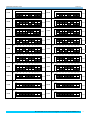
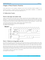
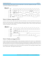
ART2543
User’s Manual
Beijing ART Technology Development Co., Ltd.
ART2542 Counter Card
V6.0.15
Contents
Contents ................................................................................................................................................................................2
Chapter 1 Overview ..............................................................................................................................................................3
Chapter 2 Components Layout Diagram and a Brief Description .......................................................................................4
2.1 The Main Component Layout Diagram ..................................................................................................................4
2.2 The Function Description for the Main Component ...............................................................................................4
2.2.1 Signal Input and Output Connectors ............................................................................................................4
2.2.2 Board Base Address Selection .....................................................................................................................5
Chapter 3 Signal Connectors................................................................................................................................................7
3.1 The Definition of Signal Input and Output Connectors ..........................................................................................7
3.2 Timer/Counter Signal Connection...........................................................................................................................8
Chapter 4 Timer/Counter Function.......................................................................................................................................9
4.1 Subtraction Counter ................................................................................................................................................9
4.2 Addition Counter...................................................................................................................................................12
4.3 Frequency Measurement Function ........................................................................................................................15
Chapter 5 Address Allocation Table....................................................................................................................................16
Chapter 6 Notes, Calibration and Warranty Policy............................................................................................................20
6.1 Notes .....................................................................................................................................................................20
6.2 Warranty Policy.....................................................................................................................................................20
Products Rapid Installation and Self-check ........................................................................................................................21
Rapid Installation ........................................................................................................................................................21
Self-check ...................................................................................................................................................................21
Delete Wrong Installation ...........................................................................................................................................21
BUY ONLINE at art-control.com/englishs or CALL+86-(0)10-51289836(CN)
2
ART2542 Counter Card
V6.0.15
Chapter 1 Overview
ART2543 is a Counter card based on PC104 bus. It can be directly connected with PC104 interface of computer to
constitute the laboratory, product quality testing center and systems for different areas of data acquisition, waveform
analysis and processing. It may also constitute the monitoring system for industrial production process.
Unpacking Checklist
Check the shipping carton for any damage. If the shipping carton and contents are damaged, notify the local dealer or
sales for a replacement. Retain the shipping carton and packing material for inspection by the dealer.
Check for the following items in the package. If there are any missing items, contact your local dealer or sales.
¾ ART2543 Data Acquisition Board
¾ ART Disk
a) user’s manual (pdf)
b) drive
c) catalog
¾ Warranty Card
Counter/Timer Function
¾
¾
¾
¾
¾
¾
¾
32-bit counter/timer, 8 independent counters (can be set to Up or Down Counter by the software)
Count Mode: 6 modes
Electrical Standards: TTL level
Gate (GATEn): rising edge, high level, low level
Counter Output (OUTn): high level, low level
Operating Temperature Range: 0℃~55℃
Storage Temperature Range: -20℃~70℃
Frequency Measurement Function
¾
¾
¾
¾
¾
Frequency Measurement Channels: 8-channel software selectable
Frequency Measurement Signal: 0 ~ 5V TTL level
Frequency Measurement Type: counting
Frequency Measurement Range: 1Hz~10MHz
Frequency Measurement Accuracy: ±1Hz
Other Features
Board Base Address: 300H
Dimension: 90.3mm (L)*96mm (W) *16mm (H)
BUY ONLINE at art-control.com/englishs or CALL+86-(0)10-51289836(CN)
3
ART2542 Counter Card
V6.0.15
Chapter 2 Components Layout Diagram and a Brief Description
2.1 The Main Component Layout Diagram
2.2 The Function Description for the Main Component
2.2.1 Signal Input and Output Connectors
CN1: signal input/output connector
BUY ONLINE at art-control.com/englishs or CALL+86-(0)10-51289836(CN)
4
ART2542 Counter Card
V6.0.15
2.2.2 Board Base Address Selection
ADDR1: board base address DIP switches. Board base address can be set to binary code which from 200H to 3E0H be
divided by 16, board base address defaults 300H, will occupy the base address of the date of 20consecutive I/O addresses.
Switch No. 1, 2, 3, 4, 5, 6, 7 correspond to address bits A4, A5, A6, A7, A8, A9, A10, A11(A10, A11 are reserved).
Board base address selection is as follows: when the ADDR1 switches dial to "ON" that means high virtual value is 1,
the switch to the other side means the low virtual is 0.
Board base address selection switch ADDR1shown as following:
For example, the default base addresses is300H, shown as the following:
A4
ON
A5
A6
A7
A8
A9 A10 A11
ON
ADDR1
1
2
3
4
5
6
7
8
Common base address
Adr
ADDR1
ON
A4
A5
A6
A7
A8
Adr
A9 A10 A11
ADDR1
ON
ON
ADDR
1
2
3
4
5
A4
A5
A6
A7
A8
6
7
A9 A10 A11
ON
A9 A10 A11
1
2
3
4
5
A4
A5
A6
A7
A8
6
7
8
A9 A10 A11
1
2
3
4
5
A4
A5
A6
A7
A8
6
7
230H
ADDR1
1
2
3
4
5
A4
A5
A6
A7
A8
8
A9 A10 A11
ON
ON
6
7
8
A9 A10 A11
ON
240H
ADDR
1
2
3
4
5
A4
A5
A6
A7
A8
6
7
250H
ADDR1
1
2
3
4
5
A4
A5
A6
A7
A8
8
A9 A10 A11
ON
ON
6
7
8
A9 A10 A11
ON
260H
ADDR
1
2
3
4
5
A4
A5
A6
A7
A8
6
7
270H
E
1
2
3
4
5
A4
A5
A6
A7
A8
8
A9 A10 A11
ON
ON
ADDR1
6
7
8
A9 A10 A11
ON
280H
ADDR
ON
A8
ON
ADDR
ON
A7
ADDR1
8
220H
ON
A6
210H
ON
ON
A5
ON
200H
ON
A4
1
2
3
4
5
A4
A5
A6
A7
A8
6
7
290H
ADDR1
1
2
3
4
5
A4
A5
A6
A7
A8
8
A9 A10 A11
ON
ON
6
7
8
A9 A10 A11
ON
2A0H
ADDR
1
2
3
4
5
6
7
8
2B0H
ADDR1
1
2
3
4
5
6
7
8
BUY ONLINE at art-control.com/englishs or CALL+86-(0)10-51289836(CN)
5
ART2542 Counter Card
ON
A4
A5
V6.0.15
A6
A7
A8
A9 A10 A11
ON
ON
2C0H
ADDR
ON
1
2
3
4
5
A4
A5
A6
A7
A8
6
7
A9 A10 A11
ON
1
2
3
4
5
A4
A5
A6
A7
A8
6
A9
7
A10 A11
ON
1
2
3
4
5
A4
A5
A6
A7
A8
6
7
4
5
A4
A5
A6
A7
A8
6
7
8
A9 A10 A11
1
2
3
4
5
A4
A5
A6
A7
A8
6
7
8
A9 A10 A11
310H
A9 A10 A11
ADDR1
ON
1
2
3
4
5
A4
A5
A6
A7
A8
6
7
8
A9 A10 A11
ON
1
2
3
4
5
A4
A5
A6
A7
A8
6
7
330H
ADDR1
1
2
3
4
5
A4
A5
A6
A7
A8
8
A9 A10 A11
ON
ON
6
7
8
A9 A10 A11
ON
340H
ADDR
1
2
3
4
5
A4
A5
A6
A7
A8
6
7
350H
ADDR1
1
2
3
4
5
A4
A5
A6
A7
A8
8
A9 A10 A11
ON
ON
6
7
8
A9 A10 A11
ON
360H
ADDR
1
2
3
4
5
A4
A5
A6
A7
A8
6
7
370H
ADDR1
1
2
3
4
5
A4
A5
A6
A7
A8
8
A9 A10 A11
ON
ON
6
7
8
A9 A10 A11
ON
380H
ADDR
1
2
3
4
5
A4
A5
A6
A7
A8
6
7
390H
ADDR1
1
2
3
4
5
A4
A5
A6
A7
A8
8
A9 A10 A11
ON
ON
6
7
8
A9 A10 A11
ON
3A0H
ADDR
1
2
3
4
5
A4
A5
A6
A7
A8
6
7
3B0H
ADDR1
1
2
3
4
5
A4
A5
A6
A7
A8
8
A9 A10 A11
ON
ON
6
7
8
A9 A10 A11
ON
3C0H
ADDR
ON
3
8
ADDR
ON
2
ON
320H
ON
A9 A10 A11
ADDR1
ON
ON
1
8
ADDR1
ON
A8
2F0H
ON
ON
A7
ON
ADDR
ON
A6
ADDR1
ON
300H
A5
2D0H
8
2E0H
ON
A4
ON
1
2
3
4
5
A4
A5
A6
A7
A8
6
7
3D0H
ADDR1
1
2
3
4
5
A4
A5
A6
A7
A8
8
A9 A10 A11
ON
ON
6
7
8
A9 A10 A11
ON
3E0H
ADDR
1
2
3
4
5
6
7
8
3F0H
ADDR1
1
2
3
4
5
6
7
8
BUY ONLINE at art-control.com/englishs or CALL+86-(0)10-51289836(CN)
6
ART2542 Counter Card
V6.0.15
Chapter 3 Signal Connectors
3.1 The Definition of Signal Input and Output Connectors
30-pin CN1 definition
+5V
1
2
+5V
OUT0
3
4
CLK0
GATE0
5
6
OUT1
CLK1
7
GATE1
OUT2
9
8
10
GATE2
11
12
OUT3
CLK3
13
14
GATE3
OUT4
15
16
CLK4
GATE4
17
18
OUT5
CLK5
19
20
GATE5
OUT6
21
22
CLK6
GATE6
23
24
OUT7
CLK7
25
26
GATE7
DGND
27
DGND
DGND
29
28
30
CLK2
DGND
Pin definition:
Pin name
Type
Pin function definition
CLK0~7
Input
Timer/Counter clock source input, the reference ground use O. GND
GATE0~7
Input
Timer/Counter gate input, the reference ground use O. GND
OUT0~8
Output
Timer/Counter output, the reference ground use O. GND
+5V
Output
Output +5V power
DGND
GND
Digital ground
BUY ONLINE at art-control.com/englishs or CALL+86-(0)10-51289836(CN)
7
ART2542 Counter Card
V6.0.15
3.2 Timer/Counter Signal Connection
BUY ONLINE at art-control.com/englishs or CALL+86-(0)10-51289836(CN)
8
ART2542 Counter Card
V6.0.15
Chapter 4 Timer/Counter Function
In the counter mode, we can use CNTPara. CNTMode to set Up or Down count: When CNTPara. CNTMode = 0, it is
subtraction, do subtract "1" operation, until the count value becomes 0; when CNTPara . CNTMode = 1, it is addition, do
add "1" operation, until the counter value becomes 4294967295 (232-1).
4.1 Subtraction Counter
Mode 0: Interrupt on terminal count
Under this mode, when given the initial value, if GATE is high level, the counter immediately begins to count by
subtracting “1” each time, the counter output OUT turns into low level; when the count ends and the count value
becomes 0, the counter output OUT becomes and keeps high level until given the initial value or reset. If a counter which
is counting is given a new value, the counter will begin to count from the new value by subtracting “1” each time. GATE
can be used to control the count, GATE=1 enables counting; GATE=0 disables counting.
OUT signal changes high from low can be used as interrupt request.
Time diagram is shown in Figure 1.
Figure 1
Mode 1: Hardware retriggerable one-shot
The mode can work under the role of GATE. After given the initial count value N, OUT becomes high level, the counter
begins to count until the appearance of the rising edge of GATE, at this moment OUT turns into low level; when the
count ends and the count value becomes 0, OUT becomes high level, that is, the output one-shot pulse width is
determined by the initial count value N. If the current operation does not end and another rising edge of GATE appears,
then the current count stops, the counter begins to count from N once again, and then the output one-shot pulse will be
widened. When the count reduction of the counter has not yet reached zero, but it is given a new value N1. Only when it
is the rising edge of GATE, the counter starts to count from N1.
Time diagram is shown in Figure 2.
BUY ONLINE at art-control.com/englishs or CALL+86-(0)10-51289836(CN)
9
ART2542 Counter Card
V6.0.15
Figure 2
Mode 2: Rate Generator
Under this mode, the counter is given the initial count value N and begins to count from (N-1), OUT becomes high level.
When the count value becomes 0, OUT turns into low level. After a CLK cycle, OUT resumes high level, and the counter
automatically load the initial value N and begin to count from (N-1). Thus the output will continue to output a negative
pulse, its width is equal to one clock cycle, the clock number between the two negative pulses is equal to the initial value
that is given to the counter. GATE=1 enables counting; GATE=0 disables counting. GATE has no effect on OUT. If
change the initial count when counting, it will be effective next time.
Time diagram is shown in figure 3.
Figure 3
Mode 3: Square wave mode
Similar to Mode 2, the counter is given the initial count value N and begins to count from (N-1). When the signal of
GATE is high level, it starts to count, timer/counter begins to count by subtracting “1” each time, more than half the
initial count value. The output OUT has remained high level, when the count value is more than half of the initial count
value; but the output OUT becomes low level, when the count value is less than half of the initial value. If the initial
count value N is an even number, the output is 1:1 square-wave; if the initial count value N is an odd number, the output
OUT has remained high level during the previous (n +1)/2 count period; but the output OUT becomes low level during
the post (n-1)/2 count period, that is, the high level has one clock cycle more than the low level. If change the initial
BUY ONLINE at art-control.com/englishs or CALL+86-(0)10-51289836(CN)
10
ART2542 Counter Card
V6.0.15
count when counting, it will be effective next time. When GATE = 0, the count is prohibited, when GATE = 1, the count
is permitted. Time diagram is shown in figure 4.
Figure 4
Mode 4: Software triggered strobe
Under this mode, the counter is given the initial count value N and begins to count, the output OUT becomes high level.
When the count value becomes 0, it immediately outputs a negative pulse which is equal to the width of one clock cycle.
If given a new count value when counting, it will be effective immediately. GATE=1 enables counting; GATE=0 disables
counting. Time diagram is shown in figure 5.
Figure 5
Mode 5: Hardware triggered strobe
Under this mode, when the signal of GATE is on the rising edge, the counter starts to count (so it is called hardware
trigger), the output OUT has remained high level. When the count value becomes 0, it outputs a negative pulse which is
equal to the width of one clock cycle. And then the rising edge of GATE signal can re-trigger, the counter starts to count
from the initial count value again, in the count period, the output has remained high level. When the count reduction of
the counter has not yet reached zero, but it is given a new value N1. Only when it is the rising edge of GATE, the counter
starts to count from N1. Time diagram is shown in figure 6.
BUY ONLINE at art-control.com/englishs or CALL+86-(0)10-51289836(CN)
11
ART2542 Counter Card
V6.0.15
Figure 6
4.2 Addition Counter
For illustration, make M = 4294967295 = 232-1, the maximum count value of the addition.
If the initial value is 4,294,967,291, is recorded as (M-4); if it is 4,294,967,292, is recorded as (M-3), and so on.
Mode 0: Interrupt on terminal count
Under this mode, when given the initial value n, if GATE is high level, the counter immediately begins to count by
addition “1” each time, the counter output OUT turns into low level; when the count ends and the count value becomes
M, the counter output OUT becomes and keeps high level until given the initial value or reset. If a counter which is
counting is given a new value, the counter will begin to count from the new value by addition “1” each time. GATE can
be used to control the count, GATE=1 enables counting; GATE=0 disables counting.
OUT signal changes from low to high can be used as interrupt request.
Time diagram is shown in Figure 7.
Figure 7
Mode 1: Hardware retriggerable one-shot
The mode can work under the role of GATE. After given the initial count value n, OUT becomes high level, the counter
begins to count until the appearance of the rising edge of GATE, at this moment OUT turns into low level; when the
count ends and the count value becomes M, OUT becomes high level, that is, the output one-shot pulse width is
determined by the M and initial count value n (M-n). If the current operation does not end and another rising edge of
BUY ONLINE at art-control.com/englishs or CALL+86-(0)10-51289836(CN)
12
ART2542 Counter Card
V6.0.15
GATE appears, then the current count stops, the counter begins to count from n once again, and then the output one-shot
pulse will be widened. When the count reduction of the counter has not yet reached M, but it is given a new value n1.
Only when it is the rising edge of GATE, the counter starts to count from n1.
Time diagram is shown in Figure 8.
Figure 8
Mode 2: Rate Generator
Under this mode, the counter is given the initial count value n and begins to count from (n+1), OUT becomes high level.
When the count value becomes M, OUT turns into low level. After a CLK cycle, OUT resumes high level, and the
counter automatically load the initial valuen and begin to count from (n+1). Thus the output will continue to output a
negative pulse, its width is equal to one clock cycle, the clock number between the two negative pulses is equal to the
difference of the M and initial value that is given to the counter (M-n). GATE=1 enables counting; GATE=0 disables
counting. GATE has no effect on OUT. If change the initial count when counting, it will be effective next time.
Time diagram is shown in figure 9.
Figure 9
Mode 3: Square wave mode
Similar to Mode 2, the counter is given the initial count value n and begins to count from (n+1). When the signal of
GATE is high level, it starts to count, timer/counter begins to count by addition “1” each time, after finish the first half
count, the output OUT has remained high level, when do the post half count, the output OUT becomes low leve. If the
initial count value n is an even number, the output is 1:1 square-wave; if the initial count value n is an odd number, the
output OUT has remained high level during the previous (M-n+1)/2 count period; but the output OUT becomes low level
BUY ONLINE at art-control.com/englishs or CALL+86-(0)10-51289836(CN)
13
ART2542 Counter Card
V6.0.15
during the post (M-n-1)/2 count period, that is, the high level has one clock cycle more than the low level. If change the
initial count when counting, it will be effective next time. GATE=1 enables counting; GATE=0 disables counting. the
count is permitted. Time diagram is shown in figure 10.
Figure 10
Mode 4: Software triggered strobe
Under this mode, the counter is given the initial count value n and begins to count, the output OUT becomes high level.
When the count value becomes M, it immediately outputs a negative pulse which is equal to the width of one clock cycle.
If given a new count value when counting, it will be effective immediately. GATE=1 enables counting; GATE=0 disables
counting. Time diagram is shown in figure 11.
Figure 11
Mode 5: Hardware triggered strobe
Under this mode, when the signal of GATE is on the rising edge, the counter starts to count (so it is called hardware
trigger), the output OUT has remained high level. When the count value becomes M, it outputs a negative pulse which is
equal to the width of one clock cycle. And then the rising edge of GATE signal can re-trigger, the counter starts to count
from the initial count value again, in the count period, the output has remained high level. When the count addition of the
counter has not yet reached M, but it is given a new value n1. Only when it is the rising edge of GATE, the counter starts
to count from n1. Time diagram is shown in figure 12.
BUY ONLINE at art-control.com/englishs or CALL+86-(0)10-51289836(CN)
14
ART2542 Counter Card
V6.0.15
Figure 12
4.3 Frequency Measurement Function
When the unknown frequency signal is a digital high-frequency signal, we can use of frequency measurement counting.
In this mode, first, set the timing t0 of the counter, hardware test count the number n in t0, then we can calculate the
frequency signal cycle to get the signal frequency, see figure below:
Time t0, the number of pulses n
Frequency Measurement Function
As shown above, the frequency of the signal is 1/ (t0/n).
BUY ONLINE at art-control.com/englishs or CALL+86-(0)10-51289836(CN)
15
ART2542 Counter Card
V6.0.15
Chapter 5 Address Allocation Table
ART2543 register address allocation table
Base address+0x0
write control address
Base address +0x2 write data
Base address +0x2 read data
0x0000
Low 16-bit initial value of counter 0
Low 16-bit current value of counter 0
0x0001
High 16-bit initial value of counter 0
High 16-bit current value of counter 0
0x0002
Low 16-bit initial value of counter 1
Low 16-bit current value of counter 1
0x0003
High 16-bit initial value of counter 1
High 16-bit current value of counter 1
0x0004
Low 16-bit initial value of counter 2
Low 16-bit current value of counter 2
0x0005
High 16-bit initial value of counter 2
High 16-bit current value of counter 2
0x0006
Low 16-bit initial value of counter 3
Low 16-bit current value of counter 3
0x0007
High 16-bit initial value of counter 3
High 16-bit current value of counter 3
0x0008
Low 16-bit initial value of counter 4
Low 16-bit current value of counter 4
0x0009
High 16-bit initial value of counter 4
High 16-bit current value of counter 4
0x000a
Low 16-bit initial value of counter 5
Low 16-bit current value of counter 5
0x000b
High 16-bit initial value of counter 5
High 16-bit current value of counter 5
0x000c
Low 16-bit initial value of counter 6
Low 16-bit current value of counter 6
0x000d
High 16-bit initial value of counter 6
High 16-bit current value of counter 6
0x000e
Low 16-bit initial value of counter 7
Low 16-bit current value of counter 7
Ox000f
High 16-bit initial value of counter 7
High 16-bit current value of counter 7
0x0010
Low 3-bit, counter 0 mode control word
Read counter 0 mode control word
0x0011
Low 3-bit, counter 1 mode control word
Read counter 1 mode control word
0x0012
Low 3-bit, counter 2 mode control word
Read counter 2 mode control word
0x0013
Low 3-bit, counter 3 mode control word
Read counter 3 mode control word
0x0014
Low 3-bit, counter 4 mode control word
Read counter 4 mode control word
0x0015
Low 3-bit, counter 5 mode control word
Read counter 5 mode control word
0x0016
Low 3-bit, counter 6 mode control word
Read counter 6 mode control word
0x0017
Low 3-bit, counter 7 mode control word
Read counter 7 mode control word
0x0018
Low 8-bit, counter UP and Down control
Lowest bit [0]: counter 0 addition and
subtraction control
...
Highest bit [7]: counter 7 addition and
subtraction control
Read counter UP and Down control signal
Lowest bit [0]: counter 0 addition and
subtraction control
…
Highest bit [7]: counter 7 addition and
subtraction control
0x0019
Lowest bit [0]: I/O device interrupt enable
output
Lowest bit [0]: read I/O device interrupt enable
output
0x001a
Lowest bit [0]: I/O device DMA enable
interrupt request
Lowest bit [0]: read I/O device DMA enable
interrupt request
0x001b
Lowest bit [0]: IO channel ready to enable
output
Lowest bit [0]: read IO channel ready to enable
output
0x001c
Low 3-bit, interrupt control
Lowest bit [0]: interrupt request
Read interrupt control
Lowest bit [0]: interrupt request
BUY ONLINE at art-control.com/englishs or CALL+86-(0)10-51289836(CN)
16
ART2542 Counter Card
V6.0.15
Higher bit [1]: DMA interrupt request
Highest bit [2]: IO channel ready
Higher bit [1]: DMA interrupt request
Highest bit [2]: IO channel ready
0x001d
Lowest bit [0]: The first channel function
selection
0: timer count 1: frequency measurement
Lowest bit [0] is valid, the end flag signal of the
first channel frequency measurement
= 0: the end of frequency measurement
= 1: doing frequency measurement counting
0x001e
Lowest bit [0]: The first channel clear signal
0: clear 1: normal count
Lowest bit [0] is valid, the end flag signal of the
second channel frequency measurement
= 0: the end of frequency measurement
= 1: doing frequency measurement counting
0x001f
Lowest bit [0] is effective, the first channel
test frequency pulse width setting,
a
period of high-level that time 1s
Lowest bit [0] is valid, the end flag signal of the
third channel frequency measurement
= 0: the end of frequency measurement
= 1: doing frequency measurement counting
0x0020
Lowest bit [0] is effective, the second
channel test frequency pulse width setting,
a period of high-level that time 1s
Lowest bit [0] is valid, the end flag signal of the
fourth channel frequency measurement
= 0: the end of frequency measurement
= 1: doing frequency measurement counting
0x0021
Lowest bit [0] is effective, the third channel
test frequency pulse width setting,
a
period of high-level that time 1s
Lowest bit [0] is valid, the end flag signal of the
fifth channel frequency measurement
= 0: the end of frequency measurement
= 1: doing frequency measurement counting
0x0022
Lowest bit [0] is effective, the fourth
channel test frequency pulse width setting,
a period of high-level that time 1s
Lowest bit [0] is valid, the end flag signal of the
sixth channel frequency measurement
= 0: the end of frequency measurement
= 1: doing frequency measurement counting
0x0023
Lowest bit [0] is effective, the fifth channel
test frequency pulse width setting,
a
period of high-level that time 1s
Lowest bit [0] is valid, the end flag signal of the
seventh channel frequency measurement
= 0: the end of frequency measurement
= 1: doing frequency measurement counting
0x0024
Lowest bit [0] is effective, the sixth channel
test frequency pulse width setting,
a
period of high-level that time 1s
Lowest bit [0] is valid, the end flag signal of the
eighth channel frequency measurement
= 0: the end of frequency measurement
= 1: doing frequency measurement counting
0x0025
Lowest bit [0] is effective, the seventh
channel test frequency pulse width setting,
a period of high-level that time 1s
The first channel frequency measurement,
standard counting value low 16-bit
0x0026
Lowest bit [0] is effective, the eighth
channel test frequency pulse width setting,
a period of high-level that time 1s
The first channel frequency measurement,
standard counting value high 16-bit
0x0027
Lowest bit [0]: The second channel clear
signal
0: clear 1: normal count
The second channel frequency measurement,
standard counting value low 16-bit
0x0028
Lowest bit [0]: The third channel clear
signal
The second channel frequency measurement,
standard counting value high 16-bit
BUY ONLINE at art-control.com/englishs or CALL+86-(0)10-51289836(CN)
17
ART2542 Counter Card
V6.0.15
0: clear 1: normal count
0x0029
Lowest bit [0]: The fourth channel clear
signal
0: clear 1: normal count
The third channel frequency measurement,
standard counting value low 16-bit
0x002a
Lowest bit [0]: The fifth channel clear
signal
0: clear 1: normal count
The third channel frequency measurement,
standard counting value high 16-bit
0x002b
Lowest bit [0]: The sixth channel clear
signal
0: clear 1: normal count
The fourth channel frequency measurement,
standard counting value low 16-bit
0x002c
Lowest bit [0]: The seventh channel clear
signal
0: clear 1: normal count
The fourth channel frequency measurement,
standard counting value high 16-bit
0x002d
Lowest bit [0]: The eighth channel clear
signal
0: clear 1: normal count
The fifth channel frequency measurement,
standard counting value low 16-bit
0x002e
Lowest bit [0]: The second channel function
selection
0: timer count 1: frequency measurement
The fifth channel frequency measurement,
standard counting value high 16-bit
0x002f
Lowest bit [0]: The third channel function
selection
0: timer count 1: frequency measurement
The sixth channel frequency measurement,
standard counting value low 16-bit
0x0030
Lowest bit [0]: the fourth channel function
selection
0: timer count 1: frequency measurement
The sixth channel frequency measurement,
standard counting value high 16-bit
0x0031
Lowest bit [0]: the fifth channel function
selection
0: timer count 1: frequency measurement
The seventh channel frequency measurement,
standard counting value low 16-bit
0x0032
Lowest bit [0]: the sixth channel function
selection
0: timer count 1: frequency measurement
The seventh channel frequency measurement,
standard counting value high 16-bit
0x0033
Lowest bit [0]: the seventh channel function
selection
0: timer count 1: frequency measurement
The eighth channel frequency measurement,
standard counting value low 16-bit
0x0034
Lowest bit [0]: the eighth channel function
selection
0: timer count 1: frequency measurement
The eighth channel frequency measurement,
standard counting value high 16-bit
0x0035
The first channel frequency measurement, the
measured frequency counting value low 16-bit
0x0036
The first channel frequency measurement, the
measured frequency counting value high 16-bit
0x0037
The second channel frequency measurement, the
measured frequency counting value low 16-bit
0x0038
The second channel frequency measurement, the
measured frequency counting value high 16-bit
BUY ONLINE at art-control.com/englishs or CALL+86-(0)10-51289836(CN)
18
ART2542 Counter Card
V6.0.15
0x0039
The third channel frequency measurement, the
measured frequency counting value low 16-bit
0x003a
The third channel frequency measurement, the
measured frequency counting value high 16-bit
0x003b
The fourth channel frequency measurement, the
measured frequency counting value low 16-bit
0x003c
The fourth channel frequency measurement, the
measured frequency counting value high 16-bit
0x003d
The fifth channel frequency measurement, the
measured frequency counting value low 16-bit
0x003e
The fifth channel frequency measurement, the
measured frequency counting value high 16-bit
0x003f
The sixth channel frequency measurement, the
measured frequency counting value low 16-bit
0x0040
The sixth channel frequency measurement, the
measured frequency counting value high 16-bit
0x0041
The seventh channel frequency measurement,
the measured frequency counting value low
16-bit
0x0042
The seventh channel frequency measurement,
the measured frequency counting value high
16-bit
0x0043
The eighth channel frequency measurement, the
measured frequency counting value low 16-bit
0x0044
The eighth channel frequency measurement, the
measured frequency counting value high 16-bit
BUY ONLINE at art-control.com/englishs or CALL+86-(0)10-51289836(CN)
19
ART2542 Counter Card
V6.0.15
Chapter 6 Notes, Calibration and Warranty Policy
6.1 Notes
In our products’ packing, user can find a user manual, ART2543 module and a quality guarantee card. Users must keep
quality guarantee card carefully, if the products have some problems and need repairing, please send products together
with quality guarantee card to ART, we will provide good after-sale service and solve the problem as quickly as we can.
When using ART2543, in order to prevent the IC (chip) from electrostatic harm, please do not touch IC (chip) in the
front panel of ART2543module.
6.2 Warranty Policy
Thank you for choosing ART. To understand your rights and enjoy all the after-sales services we offer, please read the
following carefully.
1. Before using ART’s products please read the user manual and follow the instructions exactly. When sending in
damaged products for repair, please attach an RMA application form which can be downloaded from:
www.art-control.com.
2. All ART products come with a limited two-year warranty:
¾ The warranty period starts on the day the product is shipped from ART’s factory
¾ For products containing storage devices (hard drives, flash cards, etc.), please back up your data before sending
them for repair. ART is not responsible for any loss of data.
¾ Please ensure the use of properly licensed software with our systems. ART does not condone the use of pirated
software and will not service systems using such software. ART will not be held legally responsible for products
shipped with unlicensed software installed by the user.
3. Our repair service is not covered by ART's guarantee in the following situations:
¾ Damage caused by not following instructions in the User's Manual.
¾ Damage caused by carelessness on the user's part during product transportation.
¾ Damage caused by unsuitable storage environments (i.e. high temperatures, high humidity, or volatile chemicals).
¾ Damage from improper repair by unauthorized ART technicians.
¾ Products with altered and/or damaged serial numbers are not entitled to our service.
4. Customers are responsible for shipping costs to transport damaged products to our company or sales office.
5. To ensure the speed and quality of product repair, please download an RMA application form from our company
website.
BUY ONLINE at art-control.com/englishs or CALL+86-(0)10-51289836(CN)
20
ART2542 Counter Card
V6.0.15
Products Rapid Installation and Self-check
Rapid Installation
Product-driven procedure is the operating system adaptive installation mode. After inserting the disc, you can select the
appropriate board type on the pop-up interface, click the button【driver installation】; or select CD-ROM drive in
Resource Explorer, locate the product catalog and enter into the APP folder, and implement Setup.exe file. After the
installation, pop-up CD-ROM, shut off your computer, insert the PCI card. If it is a USB product, it can be directly
inserted into the device. When the system prompts that it finds a new hardware, you do not specify a drive path, the
operating system can automatically look up it from the system directory, and then you can complete the installation.
Self-check
At this moment, there should be installation information of the installed device in the Device Manager (when the device
does not work, you can check this item.). Open "Start -> Programs -> ART Demonstration Monitoring and Control
System -> Corresponding Board -> Advanced Testing Presentation System", the program is a standard testing procedure.
Based on the specification of Pin definition, connect the signal acquisition data and test whether AD is normal or not.
Connect the input pins to the corresponding output pins and use the testing procedure to test whether the switch is
normal or not.
Delete Wrong Installation
When you select the wrong drive, or viruses lead to driver error, you can carry out the following operations: In Resource
Explorer, open CD-ROM drive, run Others-> SUPPORT-> PCI.bat procedures, and delete the hardware information that
relevant to our boards, and then carry out the process of section I all over again, we can complete the new installation.
BUY ONLINE at art-control.com/englishs or CALL+86-(0)10-51289836(CN)
21