1
MOACON User’s Manual
Modular Industrial Controller
MOACON
User's Manual
Last Updated: 2015-10-13
* This manual is published in electronic format only.
“Everything for Embedded Control”
Comfile Technology Inc.
www.ComfileTech.com
Copyright 1996,2011 Comfile Technology
Comfile Technology
MOACON – User's Manual
1 of 162
MOACON User’s Manual
Notice
This manual may be changed or updated without notice. Comfile Technology Inc. is not responsible for any
actions taken outside the explanation of this manual. This product is protected by patents across the world.
You may not change, copy, reproduce, or translate it without the consent of Comfile Technology Inc.
Warranty
Comfile Technology provides a one-year warranty on its products against defects in materials and
workmanship. If you discover a defect, Comfile Technology will, at its option, repair the product, replace the
product, or refund the purchase price. Simply return the product with a description of the problem and a
copy of your invoice (if you do not have your invoice, please include your name and telephone number). This
warranty does not apply if the product has been modified or damaged by accident, abuse, or misuse.
30-Day Money-Back Guarantee
If, within 30 days of having received your product, you find that it does not suit your needs, you may return
it for a refund. Comfile Technology will refund the purchase price of the product, excluding
shipping/handling costs. This does not apply if the product has been altered or damaged.
Disclaimer of Liability
Comfile Technology Inc. is not responsible for special, incidental, or consequential damages resulting from
any breach of warranty, or under any legal theory, including lost profits, downtime, goodwill, damage to or
replacement of equipment or property, and costs or recovering, reprogramming, or reproducing any data
stored in or use with Comfile Technology products.
Copyright & Trademarks
CUBLOC™ is a registered trademark of Comfile Technology Inc.
WINDOWS is a trademark of Microsoft Corporation.
Other trademarks are of their respective owners.
Copyright © 2006, 2011 by Comfile Technology Inc. All rights reserved.
Comfile Technology
MOACON – User's Manual
2 of 162
MOACON User’s Manual
Introduction
The MOACON is a C-programmable modular industrial controller. Its modular design enables customers to
purchase just the modules needed, and aggregate them in a way that customizes the MOACON precisely for
a product's specific requirements, and provides adaptability should those requirements change.
MOACON's Primary Features
1.
2.
3.
4.
5.
Modular Design
C Programmable
32 bit ARM Processor
USB Downloading and Debugging
MOACON Studio - Free Integrated Development
Environment (IDE) Software
The MOACON boasts a 32-bit ARM CPU Module for fast and complex computation and data processing.
Individual modules include features for Digital I/O, Relay Output, Analog-to-Digital and Digital-toAnalog Conversion, Motor control, Temperature Monitoring, RS-232 Communication, Ethernet, and
the potential for more.
The free integrated development environment software, MOACON Studio, features a C compiler, source
editor, RS-232 communication, USB downloading and debugging, and more. The source editor features
syntax highlighting, command completion, and context sensitive help making learning, developing, and
testing MOACON software projects a truly productive and enjoyable experience.
We hope that you find the MOACON's unique features and flexibility ideally suited for both your current and
future projects.
Comfile Technology
Comfile Technology
MOACON – User's Manual
3 of 162
MOACON User’s Manual
Frequently Asked Questions
Q: What software is needed to use the MOACON?
You only need MOACON Studio. It is an integrated development environment that contains everything
you need to program the MOACON. It can be downloaded from www.ComfileTech.com.
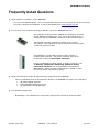
Q: I'm currently using Comfile Technology's CUBLOC. How is the MOACON different?
The CUBLOC is a microcontroller capable of simultaneous execution
of both BASIC and Ladder Logic. The code is interpreted which, in
comparison with the MOACON, results is a slower execution speed.
The CUBLOC is primary targeted for customers who wish to
manufacture mass quantities of custom PCB products with the goal
of reducing production costs.
The MOACON is a 32-bit ARM processor based, modular, C
programmable controller. The code is compiled, rather than
interpreted resulting in much faster execution.
Due to the MOACON's modular design, a variety of features, such
as Ethernet, temperature monitoring, digital-to-analog
conversion, and more, can be aggregated to customize the
MOACON for a specific product's requirements or added at a later
time as a product's requirements change.
Q: What's the maximum number of digital I/O ports supported by the MOACON?
Used
in combination with the I/O Expansion Modules, the MOACON can support up to 256 ports
48 Default Digital I/O Ports
128 Expandable Digital Input Ports
80 Expandable Relay Output Ports
Q: Is multitasking supported?
Multitasking is not supported, but using timers, background processing can be simulated.
Comfile Technology
MOACON – User's Manual
4 of 162
MOACON User’s Manual
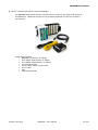
Q: What is needed to get started using the MOACON?
The MOACON START PACK contains everything that is needed to get started and should be
purchased first. Additional modules can be purchased separately to fulfill any remaining
requirements.
START PACK Contents:
MOACON CPU Module: DP-CPU500
8-Pin Digital Input Module: CF-DIDC8
8-Pin Digital Output Module: CF-DORL8
10-Slot Module Base
Power Supply: 24VDC 0.62A Output
Power Cable
Wire
USB Download Cable
Comfile Technology
MOACON – User's Manual
5 of 162
MOACON User’s Manual
Table of Contents
Chapter 1 MOACON Overview....................................................................................................... 10
MOACON Studio...........................................................................................................................11
CPU Module.................................................................................................................................12
Modules......................................................................................................................................13
Module Board...............................................................................................................................14
Installing General DIO Modules.......................................................................................................15
Installing Expansion DIO Modules...................................................................................................17
Installing Analog Modules..............................................................................................................20
Installing Special Purpose Modules..................................................................................................21
Installing Motion Control Modules...................................................................................................22
Module Installation Summary.........................................................................................................23
Special Purpose Modules.......................................................................................................23
Digital IO Modules................................................................................................................23
Analog Modules, Motion Control Modules, Expansion Digital I/O Modules......................................23
Small System Configuration...........................................................................................................24
Chapter 2 Setup.............................................................................................................................. 26
MOACON CPU Module....................................................................................................................27
DP-CPU500 Specifications......................................................................................................27
Installation..................................................................................................................................28
Supplying Power...........................................................................................................................29
Surge Killer..................................................................................................................................30
Power Relay Wiring.......................................................................................................................31
Relay Power Wiring.......................................................................................................................32
Software Installation.....................................................................................................................34
Chapter 3 Programming the MOACON......................................................................................... 42
MOACON Studio...........................................................................................................................43
Creating a Project.........................................................................................................................44
Compiling and Executing a Project..................................................................................................46
Compiler Errors............................................................................................................................49
Adding Source Files to a Project......................................................................................................50
Debug Terminal............................................................................................................................52
debugCls..................................................................................................................................52
debugLocate.............................................................................................................................52
debugPut..................................................................................................................................52
printf.......................................................................................................................................52
Data Types..................................................................................................................................54
Memory.......................................................................................................................................55
Chapter 4 System Library.............................................................................................................. 56
delay.......................................................................................................................................57
statusLed.................................................................................................................................58
Real-Time Clock...........................................................................................................................59
rtcRead....................................................................................................................................60
rtcWrite....................................................................................................................................60
FRAM Functions............................................................................................................................61
framWrite.................................................................................................................................61
framRead.................................................................................................................................61
Watchdog Timer...........................................................................................................................63
Comfile Technology
MOACON – User's Manual
6 of 162
MOACON User’s Manual
wdtOn......................................................................................................................................63
wdtClear...................................................................................................................................63
Timer..........................................................................................................................................65
startTimerEvent........................................................................................................................65
timerEvent................................................................................................................................65
stopTimerEvent.........................................................................................................................66
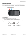
External Interrupts.......................................................................................................................67
startExtIntEvent........................................................................................................................67
extIntEvent...............................................................................................................................68
stopExtIntEvent.........................................................................................................................69
Chapter 5 Digital I/O Modules........................................................................................................ 70
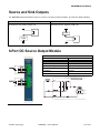
Source and Sink Outputs...............................................................................................................71
8-Port DC Source Output Module....................................................................................................71
CF-DOSO8 Specifications.......................................................................................................71
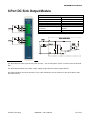
8-Port DC Sink Output Module........................................................................................................72
CF-DOSI8 Specifications........................................................................................................72
8-Port Relay Output Module...........................................................................................................73
CF-DORL8 Specifications.......................................................................................................73
Digital Output Module Library.........................................................................................................74
portInit....................................................................................................................................74
portOut....................................................................................................................................76
portBlockOut.............................................................................................................................76
portOff.....................................................................................................................................76
portOn.....................................................................................................................................76
portReverse..............................................................................................................................77
portOutStat..............................................................................................................................77
8-Port Digital Input Module............................................................................................................78
Digital Input Module Library...........................................................................................................79
portIn......................................................................................................................................79
portBlockIn...............................................................................................................................79
16-Port Digital Input Expansion Module...........................................................................................80
I2-EDI16 Specifications.........................................................................................................80
Digital Input Expansion Module Library............................................................................................81
eportIn.....................................................................................................................................81
eportBlockIn.............................................................................................................................81
8-Port Relay Output Expansion Module............................................................................................82
RS-EDOR8 Specifications.......................................................................................................82
Relay Output Expansion Module Library...........................................................................................83
eRelay.....................................................................................................................................83
eRelayBlock..............................................................................................................................83
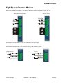
Chapter 6 High-Speed Counter Module........................................................................................ 84
High-Speed Counter Module...........................................................................................................85
High-Speed Counter Module Library................................................................................................86
countMode................................................................................................................................86
count.......................................................................................................................................87
countPrescaler..........................................................................................................................88
countReset...............................................................................................................................88
pwm........................................................................................................................................89
pwmOff....................................................................................................................................90
Comfile Technology
MOACON – User's Manual
7 of 162
MOACON User’s Manual
freqOut....................................................................................................................................91
Using the PWM Output..................................................................................................................92
Chapter 7 Communication Module................................................................................................ 94
Communication Module.................................................................................................................95
Communication Module Library.......................................................................................................97
openCom..................................................................................................................................97
comPut....................................................................................................................................99
comPrint.................................................................................................................................100
comGet..................................................................................................................................101
comGetInterval.......................................................................................................................102
comFlush................................................................................................................................103
comGets.................................................................................................................................103
comPuts.................................................................................................................................104
comPower...............................................................................................................................104
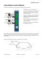
Chapter 8 Motion Control Module............................................................................................... 106
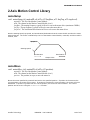
2-Axis Motion Control Module.......................................................................................................107
Open-Loop System.............................................................................................................108
2-Axis Motion Control Library.......................................................................................................109
motorSetup.............................................................................................................................109
motorMove.............................................................................................................................109
setMotorPos............................................................................................................................110
getMotorPos............................................................................................................................110
motorStop..............................................................................................................................110
motorStat...............................................................................................................................111
Chapter 9 Analog Modules.......................................................................................................... 112
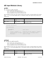
AD Input Module.........................................................................................................................113
RS-ADIN4, RS-HADIN4 Specifications....................................................................................113
RS-SADIN6 Specifications....................................................................................................113
RS-ADIN4, RS-HADIN4 Analog Input Module..................................................................................114
RS-SADIN6 6-Channel 12-bit Analog Input Module..........................................................................115
AD Input Module Library..............................................................................................................116
getAdc....................................................................................................................................116
getHadc..................................................................................................................................116
getSadc..................................................................................................................................117
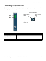
DA Voltage Output Module..........................................................................................................119
RS-DAOUT2 Specifications...................................................................................................119
dacOut...................................................................................................................................120
DA Current Output Module...........................................................................................................121
RS-DAOUT2B Specifications.................................................................................................121
dacOut2.................................................................................................................................122
Temperature Input Module...........................................................................................................123
Temperature Input Module Library................................................................................................124
getTemp.................................................................................................................................124
Chapter 10 Ethernet Module........................................................................................................ 126
Ethernet Module.........................................................................................................................127
LED Descriptions................................................................................................................127
Network Connectivity..................................................................................................................127
TCP Client-Server Communication.................................................................................................128
Ethernet Module Library...............................................................................................................129
Comfile Technology
MOACON – User's Manual
8 of 162
MOACON User’s Manual
netBegin.................................................................................................................................129
socketOpen.............................................................................................................................129
socketClose.............................................................................................................................130
listen......................................................................................................................................130
connect..................................................................................................................................130
disConnect..............................................................................................................................130
netStatus................................................................................................................................131
netSend..................................................................................................................................131
netPrint..................................................................................................................................131
netTxFree...............................................................................................................................132
netRecv..................................................................................................................................132
netRxLen................................................................................................................................132
Sample Program.........................................................................................................................132
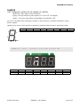
Chapter 11 Display Library.......................................................................................................... 136
Display Devices..........................................................................................................................137
CLCD Library..............................................................................................................................138
clcdI2cInit...............................................................................................................................138
clcdUartInit.............................................................................................................................138
clcdCls....................................................................................................................................138
clcdCsr...................................................................................................................................138
clcdPrint.................................................................................................................................138
clcdLocate...............................................................................................................................139
clcdBlit...................................................................................................................................139
clcdPower...............................................................................................................................139
CSG Library...............................................................................................................................140
csgPrint..................................................................................................................................141
csgPrintDot.............................................................................................................................142
csgNput..................................................................................................................................143
csgXput..................................................................................................................................144
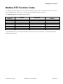
Chapter 12 Modbus RTU.............................................................................................................. 146
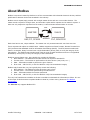
About Modbus............................................................................................................................147
Function Code 01/02: Read Coil/Input Status................................................................................149
Function Code 03/04: Read Holding/Input Registers.......................................................................150
Function Code 05: Force Single Coil..............................................................................................151
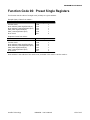
Function Code 06: Preset Single Registers.....................................................................................152
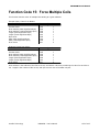
Function Code 15: Force Multiple Coils..........................................................................................153
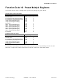
Function Code 16: Preset Multiple Registers..................................................................................154
Modbus RTU Library....................................................................................................................155
startModbusRtu.......................................................................................................................155
RTU_readCoils.........................................................................................................................155
RTU_readRegs.........................................................................................................................156
RTU_readInRegs......................................................................................................................156
RTU_writeCoil..........................................................................................................................157
RTU_writeReg.........................................................................................................................157
RTU_writeCoils........................................................................................................................157
getCrc....................................................................................................................................158
Chapter 14 Appendix.................................................................................................................... 160
External Dimensions....................................................................................................................161
Comfile Technology
MOACON – User's Manual
9 of 162
MOACON User’s Manual
Chapter 1
MOACON
Overview
Comfile Technology
MOACON – User's Manual
10 of 162
MOACON User’s Manual
MOACON Studio
MOACON Studio is the integrated development environment software needed to develop for the MOACON. It
can be downloaded from the Comfile Technology website at www.ComfileTech.com.
MOACON Studio features a C compiler, source editor, RS-232 communication, USB downloading and
debugging, and more. The source editor features syntax highlighting, command completion, and context
sensitive help making learning, developing, and testing MOACON software projects a truly productive and
enjoyable experience.
By just clicking the "Run" icon (
) MOACON Studio compiles and downloads the current MOACON project
to the CPU module where it begins executing immediately.
Once downloaded, the MOACON can be disconnected from the PC and the MOACON will execute the compiled
code as a standalone program. The program will be retained in the CPU module's flash memory even if the
MOACON is powered off.
When powered back on, the MOACON will immediately begin executing the downloaded program. A new
program can be downloaded from MOACON Studio at any time, replacing any existing program in the CPU
module's flash memory.
Comfile Technology
MOACON – User's Manual
11 of 162
MOACON User’s Manual
CPU Module
The CPU module is the MOACON's core processing module.
The CPU module features the following:
32-bit ARM Processor (ARM CORTEX)
Clock Speed: 72MHz
Program Memory: 512KB Flash Memory
Data Memory: 64KB SRAM
Non-volatile Memory: 32KB F-RAM
Built-in Real-Time Clock and Battery
Built-in RS-232 Port
LCD and 7-Segment Control Port
24V Power Input (Built -in Power Regulator)
Comfile Technology
MOACON – User's Manual
12 of 162
MOACON User’s Manual
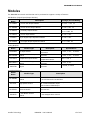
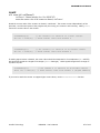
Modules
The MOACON has several modules that can be purchased to support a variety of features.
DIO Modules (Digital Input/Output Modules)
Model
Description
Name
Voltage/Current Rating
CF-DOSI8
8-pin DC Sink Output Module
DC 3.3V ~ 27V 1A
CF-DOSO8
8-pin DC Source Output Module
DC 12V ~ 24V 1A
CF-DORL8
8-pin Relay Output Module
DC 6 ~ 27V 4A
AC 6 ~ 240V 4A
CF-DIDC8
8-pin DC Input Module
DC 12V ~ 24V
I2-EDI16
16-pin Digital Input Expansion Module
DC 12V ~ 24V
RS-EDOR8
8-pin Digital Output Expansion Module
DC 6 ~ 27V 4A
AC 6 ~ 240V 4A
Analog Modules
Model
Name
RS-ADIN4
RS-HADIN4
RS-THRT4
RS-DAOUT2
RSDAOUT2B
Module Type
Description
AD Input Module
High Resolution AD Input
Module
Temperature Input Module
2-Channel DA Voltage
Output
2-Channel DA Current
Output
Specifications
4-Channel 13.3 bit AD
Conversion
4-Channel 16.6 bit AD
Converter
4-Channel PT100
Temperature Sensor
2-Channel 16-bit DA
Converter
2-Channel 16-bit DA
Converter
0~10V, 1~5V,
4~20mA
0~10V, 1~5V,
4~20mA
-100 ~ 500 C
0~10V, 0~5V
4~20mA, 0~20mA
Specialized Modules
Model
Name
Module Type
Description
Serial Communication
Module
2 RS-232 Ports
1 RS-232 Port and 1 RS-485 Port
DP-HCNT
High Speed Counter
2-Channel High-Speed Counter Input
OR 2-Channel Encoder Input
AND 8-Channel PWM Output
DP-ETHER
Ethernet Module
Ethernet Port
RS-MOT2
2-Axis Motion Control
Module
2-Axis Stepper Motor Control
DP-COMM2
Comfile Technology
MOACON – User's Manual
13 of 162
MOACON User’s Manual
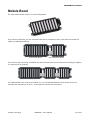
Module Board
The main module board comes in a 10-slot configuration.
If 10 slots are insufficient, a 5-slot extension board can be connected to the 10-slot board to increase the
capacity for additional modules.
10-Slot Main Board
5-Slot Extension Board
If 15 slots are still not enough, an additional 5-slot Extension board can be connected increasing the capacity
to a maximum of 20 modules.
The module board array must be terminated, so if you connected additional module boards, be sure to
terminate the last board in the array. A terminator is included with each board.
Comfile Technology
MOACON – User's Manual
14 of 162
MOACON User’s Manual
Installing General DIO Modules
WARNING: Do not plug or unplug modules while the power is on.
Module Name
CF-DOSI8
CF-DOSO8
CF-DORL8
CF-DIDC8
8-pin
8-pin
8-pin
8-pin
Module Type
DC Sink Output
DC Source Output
RELAY Output
DC Input
Maximum Number of Concurrent Modules
6
6
6
6
The CPU module must be mounted on the far left of the 10-slot main board in the position labeled "CPU".
General Digital I/O (DIO) modules can be installed in the 6 slots directly to the right of the CPU module in
the slots labeled "DIO". The slot in which the DIO module is installed determines its I/O port number.
+0
C
P
U
+10
+20
+30
+40
+50
DIO Port Number
0
10
20
30
40
50
7
17
27
37
47
57
When a general DIO module is installed in position "+0" its ports will be assigned numbers 0 through 7.
When installed in position "+30" its ports will be assigned numbers 30 through 37.
Comfile Technology
MOACON – User's Manual
15 of 162
MOACON User’s Manual
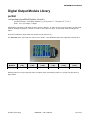
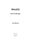
The following image illustrates a CPU module installed with 6 general DIO modules.
[One CPU module installed with 6 DIO modules]
More than one of the same type of general DIO module can be installed concurrently as shown below.
[One CPU module installed with 3 identical output modules]
Comfile Technology
MOACON – User's Manual
16 of 162
MOACON User’s Manual
Installing Expansion DIO Modules
WARNING: Do not plug or unplug modules while the power is on.
Model Name
I2-EDI16
RS-EDOR8
Maximum Number of Concurrent
Modules
Model Type
16-pin Expansion Digital Input Module
8-pin Expansion Relay Output Module
8
10
The MOACON provides a total of 48 digital I/O ports. If more than 48 are needed, these expansion DIO
modules can be used to increase the number of digital I/O ports.
Up to 8 I2-EDI16 modules can be installed to expand DC input to a maximum of 128 pins. Up to 10 RSEDOR8 modules can be installed to expand relay output to a maximum of 80 pins.
The expansion DIO modules can be installed in any slot on either the 10-slot main board or the 5-slot
expansion board, except the CPU slot.
Comfile Technology
MOACON – User's Manual
17 of 162
MOACON User’s Manual
The dipswitch on the side of the I2-EDI16 digital input expansion module is used to assign the module to a
port block
Dipswitch
Configuration
1
2 3
OFF
ON
1
2 3
1
2 3
1
2 3
1
2 3
1
2 3
1
2 3
1
2 3
OFF
ON
OFF
ON
OFF
ON
OFF
ON
OFF
ON
OFF
ON
OFF
ON
Comfile Technology
Port Block
Number
Port Number
(Hexadecimal)
0
00 - 0F
1
10 - 1F
2
20 - 2F
3
30 - 3F
4
40 - 4F
5
50 - 5F
6
60 - 6F
7
70 - 7F
MOACON – User's Manual
18 of 162
MOACON User’s Manual
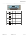
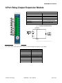
The rotary switch on the face of the RS-EDOR8 relay output expansion module is used to assign the module
to a port block.
ID (Port Block)
0
1
2
3
4
5
6
7
8
9
Comfile Technology
Output Ports
0-7
10 - 17
20 - 27
30 - 37
40 - 47
50 - 57
60 - 67
70 - 77
80 - 87
90 - 97
MOACON – User's Manual
19 of 162
MOACON User’s Manual
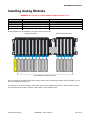
Installing Analog Modules
WARNING: Do not plug or unplug modules while the power is on.
Module Name
RS-ADIN4
RS-HADIN4
RS-THRT4
RS-DAOUT2
RS-DAOUT2B
4-Channel
4-Channel
4-Channel
2-Channel
2-Channel
Module Type
AD Input
High-Resolution AD Input
Temperature Input
DA Voltage Output
DA Current Output
Maximum Number of Concurrent Modules
10
10
10
10
10
Analog modules can be installed in any slot except the CPU slot.
10-Slot Main Board
5-Slot Extension Board
C
P
U
Analog Module Installation Slots
If the 10-slot main board does not have enough vacant slots, the analog modules can be installed in any of
the 5-slot expansion board slots.
A maximum of 10 analog modules of the same type can be installed concurrently. Each module must be
given a different ID number using the rotary switch on the module's face.
Comfile Technology
MOACON – User's Manual
20 of 162
MOACON User’s Manual
Installing Special Purpose Modules
WARNING: Do not plug or unplug modules while the power is on.
Model Name
DP-COMM2
DP-HCNT
DP-ETHER
Model Type
Communication Module
High-Speed Counter Module
Ethernet Module
Maximum Number of Concurrent Modules
1
1
1
Only one of each type of special purpose module can be installed at a time. For example, you can install one
communication module, one high-speed counter module, and one Ethernet module concurrently, but you
can't install 2 or more communication modules, high-speed counter modules, or Ethernet modules
concurrently.
5-Slot Expansion Board
10-Slot Main Board
C
P
U
DIO
Special
Purpose
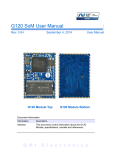
As shown in the image above, special purpose modules can be installed in any vacant slot on the 10-slot
main board. Special Purpose Modules cannot be installed in the expansion boards.
Comfile Technology
MOACON – User's Manual
21 of 162
MOACON User’s Manual
Installing Motion Control Modules
WARNING: Do not plug or unplug modules while the power is on.
Module Name
RS-MOT2
Module Type
2-Axis Motion Control Module
Maximum Number of Concurrent Modules
10
Analog modules can be installed in any slot except the CPU slot. Up to 10 Motion Control Modules can be
installed concurrently.
If the 10-slot main board does not have enough vacant slots, the motion control modules can be installed in
any of the 5-slot expansion board slots.
Up to 10 Motion Control Modules can be installed concurrently, so a maximum of 20 stepper motors can be
controlled simultaneously.
*Module names starting with "RS" imply that the module is connected internally to an RS-485 network.
Comfile Technology
MOACON – User's Manual
22 of 162
MOACON User’s Manual
Module Installation Summary
The following image summarizes the installation of each type of module.
Special Purpose Modules
(Module names beginning with "DP")
CPU
Module
Digital IO Modules
(Module names beginning
with "CF")
10-Slot Main
Board
5-Slot Expansion
Board
Analog Modules, Motion Control Modules, Expansion Digital I/O Modules
(Module names beginning with "RS" or "I2")
The appropriate installation slot can be determined just by the mode name. The special purpose modules
whose names begin with "DP" (e.g. DP-COMM2 communication module, DP-HCNT high-speed counter
module, or the DP-ETHER Ethernet module) can be installed in any of the main board's slots except the CPU
slot.
Comfile Technology
MOACON – User's Manual
23 of 162
MOACON User’s Manual
Small System Configuration
If you only require five modules or less, the 5-slot extension board can be used independently as a main
board. This is referred to as the "Small System Configuration".
With the CPU module installed in the slot labeled "CPU", the remaining 4 slots can be used to host DIO
modules, expansion DIO modules, analog modules, motion control modules, and/or special purpose
modules.
C
P
U
DIO, expansion DIO,
analog, motion
control, and/or
special purpose
modules
Note that when using the Small System Configuration, the general DIO modules can be installed in any of
the board's slots labeled "DIO". Just like the 10-slot board, the slot in which the general DIO module is
installed determines its port number.
When the 5-slot board is used as an expansion board, however, the general DIO modules cannot be installed
in the 5-slot board. When the 5-slot board is used as an expansion board, the expansion DIO modules must
be used instead.
Comfile Technology
MOACON – User's Manual
24 of 162
MOACON User’s Manual
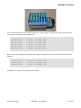
The following image shows the 5-slot board being used independently as a main board.
[CPU module, 3 DIO modules, and one communication module]
[CPU module, a high-speed counter module, and one communication module]
Comfile Technology
MOACON – User's Manual
25 of 162
MOACON User’s Manual
Chapter 2
Setup
Comfile Technology
MOACON – User's Manual
26 of 162
MOACON User’s Manual
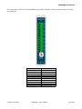
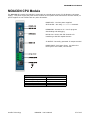
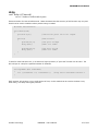
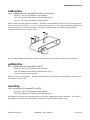
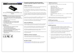
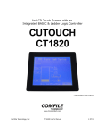
MOACON CPU Module
The MOACON CPU module (DP-CPU500) comes with an external power supply (5V 2A Output, 10W power
supply). This power supply will power all the modules in the system when connected to the CPU module, so
power supplies are not included with any other IO module.
POWER LED: Lit when power supplied.
STATUS LED: Set using statusLed command.
DOWNLOAD: Connect to PC. Use for program
downloading and debugging.
RS232 CH0: Built-in RS-232 Channel 0 for
interfacing to RS-232 capable devices.
5V OUTPUT: Internally generated 5V output terminal
POWER INPUT: 24V Power Input. Use either the
barrel jack or the header, but not both.
DP-CPU500 Specifications
Input Voltage
24VDC
Input Voltage Range
18 – 28VDC
Approx. RTC Battery Life
10 years
Operating Temperature
0 ~ 55 C
Storage Temperature
-20 ~ 70 C
Comfile Technology
MOACON – User's Manual
27 of 162
MOACON User’s Manual
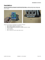
Installation
All modules should be secured to the slot board with screws. Vibration and shock can result in poor
electrical contact and other problems. Failure to secure the modules with screws may result in malfunction
and/or damage.
Please avoid operating the MOACON in the following conditions:
Where ambient temperature exceeds 55 C
Where relative humidity is not within 30 ~ 60%
Where the MOACON could be subject to excessive vibration or shock
In direct sunlight
Near a heat source
Near a transformer of other high-voltage source.
Comfile Technology
MOACON – User's Manual
28 of 162
MOACON User’s Manual
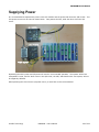
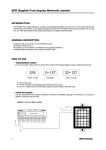
Supplying Power
It is recommended to separate the power to the CPU module and the power that drives the I/O circuits. Two
24V power sources can be used as shown below. One powers the CPU, while the other drives the I/O
circuit.
Separating the CPU's power and I/O power will result in a more stable operation. The system will be less
susceptible to noise, and if a short occurs in the I/O circuit, the CPU, and therefore the rest system, will not
be negatively affected.
When powering the CPU from an A/C power source, a noise filter is also recommended.
Comfile Technology
MOACON – User's Manual
29 of 162
MOACON User’s Manual
Surge Killer
When using the Relay Output Module with a large capacity product, it is recommended to add a relay that
can bear a large load.
When such a relay is added, turning the relay on and off can cause a large voltage surge to occur due to the
coil's inductance. This voltage surge should be removed to ensure the stability of the entire system, and the
longevity of the relay's life.
A spark killer or surge killer can be used to guard against this anomaly. As shown in the pictures below, the
surge killer should be connected in parallel to the source of the surge.
Comfile Technology
MOACON – User's Manual
30 of 162
MOACON User’s Manual
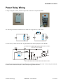
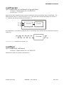
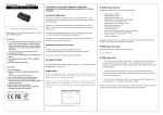
Power Relay Wiring
If using a magnetic contact, attach a surge killer as shown in the pictures below
The following schematic illustrates how to attach the surge killer to an AC circuit.
In a DC circuit, a diode can be used. A typical diode used for this purpose is the 1N4148.
DC OUTPUT (SINK)
Relay
DIODE
This method is less expensive and more effective in eliminating noise in the circuit. When using this method,
be sure not to switch the relay on or off at a frequency greater than 2Hz.
Comfile Technology
MOACON – User's Manual
31 of 162
MOACON User’s Manual
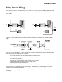
Relay Power Wiring
Do not wire the power for an external relay to the same circuit as the controller's SMPS (Switched Mode
Power Supply) as noise from the relay switching on and off can negatively influence the operation of the
power supply.
Incorrect
AC
Correct
AC
S.M.P.S
S.M.P.S
AC
RELAY
RELAY
To achieve a more reliable operation, connect a shield transformer (1:1) before the controller's power
supply.
1:1 Transformer
Noise Filter
Ground
Ground
Power Supply
Power wiring is very important. If power supply noise cannot be controlled, the system will not be stable.
Ensure the following to keep noise at a minimum.
1.
2.
3.
4.
5.
6.
7.
Power wires should be thick and twisted together to reduce noise.
Isolation transformer wires should also be twisted together to reduce noise and connected in close
proximity to the controller.
Be sure the SMPS is properly grounded.
Do not put AC and DC signals in close proximity to one another.
Separate signal wires and power wires by at least 20cm.
Separate input and output signal wires.
Keep magnetic switches, potential relays, and power relays away from the controller.
Also, be aware of the capabilities of your power supply. Overloading your power supply may result in
overheating and ultimate system failure.
Keeping your control panel properly ventilated, especially in hot weather, will help reduce the risk of
overheating.
Comfile Technology
MOACON – User's Manual
32 of 162
MOACON User’s Manual
Wiring
PVC coated wire with a thickness of about AWG20 is suitable for most I/O signals. (AWG20 wire is
available at www.ComfileTech.com).
Strip the wire with a wire-stripping tool, insert into the module's terminal block, and tighten with a
screwdriver. Soldering the ends of the wires is not recommended.
Correct
Incorrect
Be sure no bare wire is exposed outside of the terminal block as shown above.
For power signals, using a wire thickness between AWG16 ~ AWG12 is recommended.
Comfile Technology
MOACON – User's Manual
33 of 162
MOACON User’s Manual
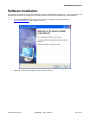
Software Installation
This section will explain how to install MOACON Studio and the MOACON's USB driver. These instructions will
describe the procedure for Windows XP, but the procedure is similar for Windows Vista and Windows 7.
1.
Download MOACON Studio setup program from the Comfile Technology website at
www.ComfileTech.com and execute in on a PC.
2.
When the window above appears, click the "Next" button.
Comfile Technology
MOACON – User's Manual
34 of 162
MOACON User’s Manual
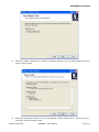
3.
When the window above appears, accept the default or change the installation folder to your liking
and click the "Next" button.
4.
When the window above appears, accept the default or change the start menu folder and click the
"Next" button.
Comfile Technology
MOACON – User's Manual
35 of 162
MOACON User’s Manual
5.
Check the "Create a desktop icon" checkbox to indicate whether or not you want a desktop icon and
click the "Next" button.
6.
Review the installation summary. If you need changes, click the "Back" button. If everything is to
your liking, click the "Install" button.
Comfile Technology
MOACON – User's Manual
36 of 162
MOACON User’s Manual
7.
MOACON Studio will begin installing. Wait for it to finish.
8.
When the installation is finished, decide if you want to run MOACON Studio immediately by checking
the "Launch Moacon Studio" checkbox, and click the "Finish" button.
Comfile Technology
MOACON – User's Manual
37 of 162
MOACON User’s Manual
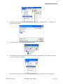
9.
When MOACON Studio is run, the main window will appear.
10. Before MOACON Studio can be used with the MOACON, the USB driver must be installed. Go to
"Start" "Programs" "Comfile Tools" "USB driver for Moacon" to begin the installation.
Comfile Technology
MOACON – User's Manual
38 of 162
MOACON User’s Manual
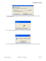
11. When the window above appears, accept the defaults or change the installation location and click
the "Install" button.
12. The installation program will scan your computer for existing drivers.
13. When the installation is complete the window above will appear. Click the "OK" button to finish.
Comfile Technology
MOACON – User's Manual
39 of 162
MOACON User’s Manual
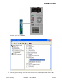
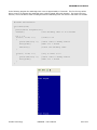
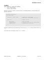
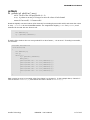
14. Once the installation is finished, power on the MOACON, and connect PC to the MOACON's
"Download" port with a USB cable.
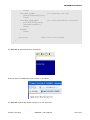
15. In the PC's Device Manager, you'll see that a COM port was created (Silicon Labs CP210x USB to
UART Bridge). In the image above the MOACON is on COM4, but every PC will be different.
Comfile Technology
MOACON – User's Manual
40 of 162
MOACON User’s Manual
16. Open MOACON Studio and select "Tools" "Comm Port Settings" from the menu.
17. Select the COM port on which the MOACON is connected. This should be the port shown in step 15
(COM4).
MOACON projects can now be created and downloaded to the MOACON using MOACON Studio.
Comfile Technology
MOACON – User's Manual
41 of 162
MOACON User’s Manual
Chapter 3
Programming
the MOACON
Comfile Technology
MOACON – User's Manual
42 of 162
MOACON User’s Manual
The MOACON is programmed using the ANSI-C programming language. C is an extremely common
programming language that has been around for more than 40 years and there are many great C
programming resources available. It would be futile and unproductive to try and reproduce that material
here, so this manual will only discuss the aspects of C programming that are applicable to the MOACON.
Readers are encouraged to obtain additional material on programming in C to supplement this manual.
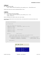
MOACON Studio
MOACON Studio is the integrated software development environment used to program the MOACON. The
image below describes the main window.
1. Source Editor
2. Project View
3. Help Window
4. Debug
Terminal
5. Output Window
1.
2.
3.
4.
5.
Source Editor – Text editor for source code.
Project View – Displays a list of all files in the current project.
Help Window – Shows command syntax and other documentation as you type in the source editor.
Debug Terminal – Output window for debugging messages.
Output Window – Shows compiler messages, download messages, and more.
Comfile Technology
MOACON – User's Manual
43 of 162
MOACON User’s Manual
Creating a Project
To create a project in MOACON Studio, choose "Project" "New Project…" from the main menu.
From the "New Project" dialog that appears, create or browse to an empty folder. The folder's name will
become the project's name. When the project is created a [ProjectName].csp file will be created in this
folder; this is the MOACON Studio project file. In the example above, a file named MyProject.csp will be
created in the folder "C:\Moacon Studio\Projects\MyProject".
Comfile Technology
MOACON – User's Manual
44 of 162
MOACON User’s Manual
3. Open File Tabs
1. Project Root
2. Default .c File
After creating a new project, the project will open in MOACON Studio and create a default [ProjectName].c
file. In the example above, for project "MyProject" a default MyProject.c file was created.
1.
2.
Project Root – The root of the project. Source files will appear as children of this root.
Default .c File – The default source file. New source files can be created and added to the project.
The source files do not have to reside in the project folder.
Open File Tabs – Any file open for editing will appear as a tab in the Source Editor Window.
3.
#include "moacon500.h"
void cmain(void)
{
//Device Declaration
//Program's Entry Point
}
The #include "moacon500.h" statement is a device declaration statement used to include code that is
specific to the model of the CPU module – in this case the DP-CPU500. It should be included at the top of
the main source file.
cmain is the program's entry point (i.e. the first function the program calls when it is executed). Note that
in most C programs, the program's entry point is usually called main, but for the MOACON, it is cmain.
Comfile Technology
MOACON – User's Manual
45 of 162
MOACON User’s Manual
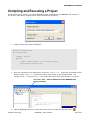
Compiling and Executing a Project
In this section we will create a very simple MOACON project, download it to the MOACON, and execute it.
The famous "Hello World" program will be used to illustrate the procedure.
1.
Create a new project called "HelloWorld".
#include "moacon500.h"
void cmain(void)
{
//Repeat Forever
while(1)
{
//Print "Hello World" to the debug console
printf("Hello World\r\n");
}
}
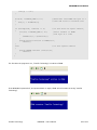
2.
Enter the code above in the HelloWorld.c source file. The while(1) code block will execute forever
without exiting. The printf statement will print "Hello World" to the Debug Terminal. The
carriage return (\r) and new line (\n) will ensure each "Hello Word" gets printed on a new line.
The "Run" Icon – Click to download to the MOACON and
begin executing
3.
With the MOACON powered on, and connected to the PC via USB, click the "Run" icon (
Comfile Technology
MOACON – User's Manual
).
46 of 162
MOACON User’s Manual
Output from the
compiler will be
displayed in the Output
Window
4.
MOACON Studio will compile the program and download it to the MOACON.
Comfile Technology
MOACON – User's Manual
47 of 162
MOACON User’s Manual
Output from the
MOACON is displayed in
the Debug Terminal
5.
The MOACON will begin executing the program immediately. Output from the programs printf
statement will be displayed in the Debug Terminal.
Note that the program is not running on the PC, it is running on the MOACON. If you disconnect the
MOACON from the PC, there will be no output in the Debug Terminal.
Comfile Technology
MOACON – User's Manual
48 of 162
MOACON User’s Manual
Compiler Errors
Often during development, syntax errors and other errors can prevent a program from being compiled.
#include "moacon500.h"
void cmain(void)
{
//Repeat Forever
while(1)
{
//Print "Hello World" to the debug console
printf("Hello World\r\n")
//ERROR: No semicolon
}
}
For example, in the source above, there is no semicolon after the printf statement. This is a syntax error
in C.
Double-Click to
scroll to the line
with the error.
When the compiler encounters such an error, a message will be displayed in the output window. You can
double-click the message in the output window, and the source editor will scroll to the line with the error.
Comfile Technology
MOACON – User's Manual
49 of 162
MOACON User’s Manual
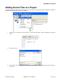
Adding Source Files to a Project
A project can contain many source files, and may be necessary to keep a large project organized. Follow the
procedure below to add source files to a project.
1.
Choose "File" "New File" from the menu. A new source file called "Text2" will appear in the source
editor.
2.
Enter some code.
3.
Save the file ("File" "Save File"), and give it a new name. In the image above, the file name will
be "sum.c".
Comfile Technology
MOACON – User's Manual
50 of 162
MOACON User’s Manual
4.
The file has now been saved, but is not yet part of the project. Choose "Project" "Add Files To
Project" from the menu.
5.
Browse to the file to add, and click the "Open" button.
6.
The new file will then appear in the Project View window. At this point, if you compile the project,
all source files will be compiled.
7.
Choose "Project" "Save Project" from the menu to save your changes to the current project.
Comfile Technology
MOACON – User's Manual
51 of 162
MOACON User’s Manual
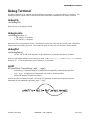
Debug Terminal
The Debug Terminal is an essential tool for displaying information on a program while it is executing. The
following functions can be used to customize the way information is displayed in the Debug Terminal.
debugCls
void debugCls()
Clears all text in the debug terminal.
debugLocate
void debugLocate(x, y)
x: The cursor's x coordinate
y: The cursor's y coordinate
Moves the cursor to the position that is x characters from the left of the Debug Terminal, and y characters
from the top of the Debug Terminal. This will be the point at which the next character will be printed.
debugPut
void debugPut(ch)
ch: The ASCII code of the character, or the character to be printed to the Debug Terminal
Prints a single ASCII character to the Debug Terminal. Both debugPut('a') and debugPut(97) print the
character "a". 97 is the ASCII code for the character "a" in decimal.
printf
u32 printf(char *formatString[, arg0, ..., argn])
formatString: A character string to be printed that can optionally contain format specifiers
arg0,...,argn: An optional set of arguments to be used by format specifiers.
returns The number of characters printed.
Prints a string to the Debug Terminal. The string may optionally contain format specifiers that are
substituted by the additional arguments (arg0,…, argn).
Comfile Technology
MOACON – User's Manual
52 of 162
MOACON User’s Manual
The MOACON supports the following format specifiers:
Specifier
%d
%u
%x
%X
%c
%f
%s
%e
%%
Description
Signed decimal integer
Unsigned decimal integer
Unsigned lower case hexadecimal integer
Unsigned upper case hexadecimal integer
A character
A decimal floating point number
A string of characters
Scientific notation
Escape '%' character
Prints
100 -10
100 12
Ab 12ab
AB 12AB
a
0.123534
Comfile Technology
7.3458485e+07
%
Examples:
int x=345;
float y=34.564;
printf("%10d\r\n",x);
printf("%-10d\r\n",x);
printf("%010d\r\n",x);
printf("%.2f\r\n",y);
//
//
//
//
prints
prints
prints
prints
"
345"
"345
"
"0000000345"
34.57
printf is an extremely common output statement in the C programming language, and readers are
encouraged to obtain additional C programming resources to learn more about this function.
Comfile Technology
MOACON – User's Manual
53 of 162
MOACON User’s Manual
Data Types
The MOACON Studio compiler supports the following data types:
char
unsigned char
short
unsigned char
int
unsigned int
long
unsigned long
float
double
long long
Signed 8-bit number
Unsigned 8-bit number
Signed 16-bit number
Unsigned 16-bit number
Signed 32-bit number
Unsigned 32-bit number
Same as int
Same as unsigned int
32-bit floating point number (IEEE single-precision)
64-bit floating point number (IEEE single-precision)
Signed 64-bit number
To make the syntax more compact, the following types have also been defined:
#define
#define
#define
u8
u16
u32
unsigned char
unsigned short
unsigned long
These types have already been pre-defined, so it is not necessary for users to define them. They can be
used right out of the box.
void cmain(void)
{
u8
i;
// 8-bit unsigned number
u32
li;
// 32-bit unsigned number
//...
}
Comfile Technology
MOACON – User's Manual
54 of 162
MOACON User’s Manual
Memory
The MOACON has 512KB of flash memory for executable code. However, some of this memory is consumed
by the MOACON OS. The exact amount of memory depends on the MOACON OS version, but at the time this
manual was written it was about 20KB.
The MOACON also has 64KB of data memory. Like the program memory, some of this is consumed by the
MOACON OS. Again the exact amount consumed depends on the MOACON OS version, but at the time this
manual was written it was about 10KB.
512KB
64KB
OS AREA
FLASH
Program
SRAM
Data
32KB
F-RAM
Nonvolatile Data
The size of the program can be determined when a program is compiled. If the program exceeds the
amount of available memory, an "out of memory" error will occur.
The MOACON also has 32KB of non-volatile memory that is retained even when the MOACON is powered off.
This memory can be accessed with the framRead and framWrite functions. The MOACON does not have a
battery backup feature, so, if data must be retained between power cycles, be sure to store this data in
FRAM.
Comfile Technology
MOACON – User's Manual
55 of 162
MOACON User’s Manual
Chapter 4
System Library
Comfile Technology
MOACON – User's Manual
56 of 162
MOACON User’s Manual
delay
void delay (u32 interval)
interval : Number of milliseconds to pause
Pauses execution for interval milliseconds. Please be aware that the accuracy of this function may vary and
should not be used in situations where precise timing is needed.
#include "moacon500.h"
void cmain(void)
{
portInit(2,0);
while(1)
{
portOut(20,1);
delay(100);
portOut(20,0);
delay(100);
//Initialize ports 20~27 for output
//Run forever
//Set port 20 High
//Wait for 100ms
//Set port 20 Low
//Wait for 100ms
}
}
To wait for times less than 1ms, or to achieve a higher precision, a "spin-wait" function can be used. The
CPU will spin in a loop for a specified number of iterations.
void spinWait(u32 countdown)
{
for (;countdown > 0; countdown--);
}
//Loop until countdown reaches 0
Each iteration will consume a very small amount of time, so this method can be used to simulate a very
short delay, or a delay with higher precision.
Comfile Technology
MOACON – User's Manual
57 of 162
MOACON User’s Manual
statusLed
void statusLed (u8 onoff)
onoff : 0=Off, 1=ON
Turns the status LED on the CPU Module on or off. Lighting or flashing the status LED is a simple way to
convey the status of the system. The status LED is off by default.
statusLed(1);
Comfile Technology
//Turns the status LED On.
MOACON – User's Manual
58 of 162
MOACON User’s Manual
Real-Time Clock
The MOACON CPU Module has a built in Real-Time Clock (RTC). The chip contains a temperature sensor to
compensate for drift due to temperature fluctuations. Please note, however, that although the MOACON's
RTC is better than most, it is not 100% accurate.
The RTC is powered by a battery that keeps the RTC counting when no power is supplied to the MOACON.
The battery's life span is approximately 10 years.
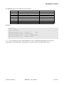
The following table illustrates the format in which the RTC data is stored in memory. Data is stored in Binary
Coded Decimal (BCD).
RTC
Address
0
1
2
3
4
5
6
Value
Second
Minute
Hour
Day
Date
Month
Year
Range
0 to 59
0 to 59
0 to 23
1 to 7
1 to 31
1 to 12
00 to 99
Bit7
Bit6
Bit5
Bit4
nd
Bit3
Bit2
Bit1
Bit0
st
2 digit
2nd digit
1 digit
1st digit
1st digit
2nd digit
1st digit
2nd digit
2nd digit
2nd digit
1st digit
1st digit
1st digit
Days of the week (the "Day" field) are coded as shown in the following table
Sunday
Monday
Tuesday
Wednesday
Thursday
Friday
Saturday
1
2
3
4
5
6
7
The hour field ranges from 0 to 23 so one can distinguish between AM and PM.
Comfile Technology
MOACON – User's Manual
59 of 162
MOACON User’s Manual
rtcRead
u8 rtcRead (u8 rtcAdr)
rtcAdr : Address of the RTC data field (e.g. day, month, year, etc...) from which to read.
Reads the RTC value from the RTC data field's address, rtcAdr.
rtcWrite
void rtcWrite(u8 rtcAdr, u8 rtcData)
rtcAdr : Address of the RTC data field (e.g. day, month, year, etc...) to set.
rtcData: Value to set
Sets the RTC data field at address rtcAdr to the value rtcData.
The following program sets the current date and time, and then prints the current date and time to the
debug console.
#include "moacon500.h"
void cmain(void)
{
//Set the current date and time
rtcWrite(6, 0x11);
//2011-03-15 (March 15, 2011)
rtcWrite(5, 0x03);
rtcWrite(4, 0x15);
rtcWrite(2, 0x13);
rtcWrite(1, 0x17);
rtcWrite(0, 0x23);
//01:17:23 pm
while(1)
//Run forever
{
//Print the current date and time to the debug
printf("The current date and time is:\r\n");
printf("20%02X-%02X-%02X %02X:%02X:%02X\r\n",
rtcRead(6), rtcRead(5), rtcRead(4),
rtcRead(2), rtcRead(1), rtcRead(0));
console
//yyyy-mm-dd hh:mm:ss
//year, month, day
//hour, minute, second
delay(1000);
}
}
Comfile Technology
MOACON – User's Manual
60 of 162
MOACON User’s Manual
FRAM Functions
The MOACON has 32KB of FRAM (Ferroelectric Random Access Memory) memory. It is non-volatile so it
retains data even without power.
Retaining memory between power cycles has traditionally been implemented using EEPROMs or battery
backup.
Battery backup uses a battery to maintain memory in internal SRAM. However, the battery must be
monitored to ensure it has a charge and is replaced periodically, which places a maintenance burden on the
operators.
EEPROMs incur a few milliseconds of latency when writing and are limited in the number of write-erase
cycles.
FRAM can retain data for about 10 years without the need for a battery backup, has a lower writing latency,
and has a greater maximum number of write-erase cycles.
framWrite
void framWrite(u16 fadr, u8 fData)
fAdr : Address in FRAM to write data
fData: Data to write
Writes fData to FRAM address fAdr. Addresses 0 through 0x7EFF are available for use. The last 256 bytes,
addresses 0x7F00 through 0x7FFF, are reserved for the system and should not be used.
framRead
u8 framRead(u16 fadr)
fAdr : Address in FRAM to read from
returns the data read
Gets a byte of data from FRAM address fAdr.
The following program demonstrates reading and writing to FRAM. If FRAM does not contain the string
"Comfile Technology" at address 0, the string is written to FRAM. After writing to FRAM, if the MOACON is
powered off and powered back on, the string will be retained.
#include "moacon500.h"
#include <string.h>
void cmain(void)
{
char text[STRING_LEN];
const char* const comfile = "Comfile Technology";
const u8 STRING_LEN = 19;
//"Comfile Technology" plus '\0' terminator
u8 i = 0;
for(i=0; i< STRING_LEN; i++)
{
Comfile Technology
//Clear text one character at a time
MOACON – User's Manual
61 of 162
MOACON User’s Manual
text[i] = '\0';
}
for(i=0; i<STRING_LEN-1; i++)
{
text[i] = framRead(i);
}
//Read data from FRAM one byte at a
//time and store in variable text
if (strcmp(text, comfile) != 0)
//If text does not equal comfile,
{
for(i=0; i<STRING_LEN-1; i++)
//write comfile to FRAM
{
//one byte at a time
framWrite(i, *(comfile+i));
}
printf("\"%s\" written to FRAM\r\n",
comfile);
}
else
//if text equals comfile
{
printf("FRAM contains \"%s\"\r\n",
comfile);
}
}
The first time the program is run, "Comfile Technology" is written to FRAM.
If the MOACON is powered off, and powered back on again, FRAM will still contain the string "Comfile
Technology".
Comfile Technology
MOACON – User's Manual
62 of 162
MOACON User’s Manual
Watchdog Timer
A watchdog timer is a timer that triggers a system reset if the system does not service the timer before a
specified timeout is reached.
The Watchdog timer will count up from 0 to
a specified timeout. When the timeout is
reached, it will reset the CPU.
Watchdog Timer
Watch Dog Timer
To prevent the CPU from being reset, the
watchdog timer must be cleared before the
timeout is reached.
CPU
Watchdog
Timer
Watch Dog
Timer
Clear
Timeout
Time Over
CPU
Run wdtClear();
Reset
wdtOn
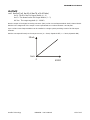
void wdtOn(u8 timeout)
timeout : A number corresponding to a specified timeout (0 ~ 6)
Enables the watchdog timer with a specified timeout, timeout. The following table maps timeout to a
corresponding time span.
timeout
0
1
2
3
4
5
6
Time Span
0.4 seconds
0.8 seconds
1.6 seconds
3.2 seconds
6.5 seconds
13 seconds
26 seconds
Time Span is accurate within 5%.
wdtClear
void wdtClear()
Resets the watchdog timer back to 0.
Comfile Technology
MOACON – User's Manual
63 of 162
MOACON User’s Manual
In the following program the watchdog timer is set to approximately 6.5 seconds. The first for-loop will be
able to count to 10 because the watchdog timer is being cleared after each iteration. The second for-loop,
however, will not be able to finish counting because the watchdog timer will reset the CPU after 6.5 seconds.
#include "moacon500.h"
void cmain(void)
{
printf("Start Program\r\n");
wdtOn(4);
//Set watchdog timer to 6.5 seconds
int i = 0;
for(i=1; i<=10; i++)
{
printf("%d\r\n", i);
delay(1000);
wdtClear();
//Count to 10
//Print count to debug console
//Wait for 1 second
//Clear the watchdog timer
}
for(i=1; i<=10; i++)
{
printf("%d\r\n", i);
delay(1000);
}
//Try to Count to 10
//Print count to debug console
//Wait for 1 second
}
Comfile Technology
MOACON – User's Manual
64 of 162
MOACON User’s Manual
Timer
A timer triggers an event at a specified periodic interval.
as 1ms.
Intervals can be as long as 65 seconds or as short
startTimerEvent
void startTimerEvent(u16 interval)
interval : The amount of time between each event in milliseconds (1 ~ 65,535)
Starts a timer that triggers events every interval milliseconds.
These timers can be used to trigger background processes at regular intervals, thus simulating multitasking.
Care must be taken when using these timers. The process triggered by the event, i.e. service routine,
must execute in less time than the timer's interval. If the service routine cannot finish in time, the
system will never be able to exit out to the main routine.
timerEvent
void timerEvent()
This is the function that is called when a timer's event fires.
The following program demonstrates how to use the startTimerEvent function with the timerEvent
function.
#include "moacon500.h"
void cmain(void)
{
startTimerEvent(500);
//Execute timerEvent() every 500ms
while(1)
{
delay(2000);
}
//Run forever
//Pause for 2 seconds
}
void timerEvent()
{
printf("Timer Event Fired!\r\n");
}
Comfile Technology
//Print to the debug console
MOACON – User's Manual
65 of 162
MOACON User’s Manual
stopTimerEvent
void stopTimerEvent()
Stops the timer.
Comfile Technology
MOACON – User's Manual
66 of 162
MOACON User’s Manual
External Interrupts
The MOACON has the ability to receive external interrupts on ports 10 through 17. When an interrupt is
received, an interrupt service routine (ISR) is executed. A Digital Input Module can be installed in slot +10
to receive interrupt signals.
Port 10~17
CPU Module External Interrupt
startExtIntEvent
void startExtIntEvent(u8 extIntPort, u16 extIntType)
extIntPort : The port to use as an external interrupt port (10~17)
extIntType: 0=Rising Edge, 1=Falling Edge, 2=Rising and Falling Edge
Tells the MOACON to configure extIntPort as an external interrupt port. extIntType configures the interrupt
to trigger when turned on (0), when turned off(1), or when turned on or off (2).
Comfile Technology
0
1
2
Rising Edge
Turned ON
Falling Edge
Turned OFF
Rising and Falling Edge
Turned ON or OFF
MOACON – User's Manual
67 of 162
MOACON User’s Manual
extIntEvent
void extIntEvent(u8 extIntPort)
extIntPort : The port on which the interrupt was triggered
The interrupt service routine for the external interrupts. This function is executed when any of the external
events are triggered. extIntPort is the port on which the external interrupt was triggered.
#include "moacon500.h"
void cmain(void)
{
startExtIntEvent (10,0);
startExtIntEvent (11,2);
//Port 10, triggerd on rising edge
//Port 11, triggered on rising and falling edge
while(1)
//Run forever
{
printf("Main Routine \r\n");
delay(1000);
}
}
void extIntEvent(u8 extIntPort)
{
switch(extIntPort)
{
case 10:
//If event was triggered on port 10
printf("Interrupt on port 10 \r\n");
break;
case 11:
//If event was triggered on port 11
printf("Interrupt on port 11 \r\n");
break;
}
}
Comfile Technology
MOACON – User's Manual
68 of 162
MOACON User’s Manual
stopExtIntEvent
void stopExtIntEvent(u8 extIntPort)
extIntPort : The port to stop using as an external interrupt (10~17)
Stops using port extIntPort as an external interrupt.
Comfile Technology
MOACON – User's Manual
69 of 162
MOACON User’s Manual
Chapter 5
Digital I/O
Modules
Comfile Technology
MOACON – User's Manual
70 of 162
MOACON User’s Manual
Source and Sink Outputs
The MOACON Digital I/O Modules come in 2 flavors: the Source Output Module, and the Sink Output Module.
Source Output
When turned on, the load's positive terminal is
connected to the positive supply rail.
Sink Output
When turned on, the load's negative terminal is
connected to the negative supply rail.
+
Load
+
Load
8-Port DC Source Output Module
CF-DOSO8 Specifications
Ports
8
Operating Voltage
12 – 24VDC
Output Voltage
10 – 30VDC
Maximum Output Current
1A / Port, 4A / COMMON
Minimum Output Current
0.5mA
Maximum On/Off switching
1KHz (1000 times per
frequency
second)
Status LED
Lights when port is ON
Common Terminals
2 (independent)
Comfile Technology
MOACON – User's Manual
71 of 162
MOACON User’s Manual
8-Port DC Sink Output Module
CF-DOSI8 Specifications
Ports
8
Operating Voltage
3.3 – 27 VDC
Output Voltage
3 – 30VDC
Maximum Output Current
1A / Port, 4A / COMMON
Minimum Output Current
0.5mA
Maximum On/Off switching
1KHz (1000 times per
frequency
second)
Status LED
Lights when port is ON
Common Terminals
2 (independent)
The Sink Output module requires two power sources. The DC 24V power source is used to drive the internal
FET.
The Sink Output Module has a wider output voltage range than the Source Output Module.
DC Output Modules can output a pulse of up to 1KHz meaning it can be switched on and off at about 1000
times per second.
Comfile Technology
MOACON – User's Manual
72 of 162
MOACON User’s Manual
8-Port Relay Output Module
CF-DORL8 Specifications
Ports
8
Operating Voltage
6-27VDC / 6-240VAC
Output Voltage
5-30VDC / 5-264 VAC
Maximum Output Current
4 A / Port, 4A / COMMON
Minimum Output Current
100 mA @ 5VDC
Maximum On/Off Switching
25Hz (25 times per second)
Frequency
Status LED
Lights when port is ON
Common Terminals
8 (Independent)
Internal module circuitry
OUTPUT
COM
This is a 4A load per port relay output module capable of up to AC 240V.
If a high switching frequency is needed, using the DC Output Modules is recommended.
After prolonged used, the relay's mechanical contacts may become worn and will need to be replaced.
(Individual relays are not available, so the entire module will need to be replaced).
Comfile Technology
MOACON – User's Manual
73 of 162
MOACON User’s Manual
Digital Output Module Library
portInit
void portInit(u8 portBlockNumber, u8 mode)
portBlockNumber: Port Block Number (e.g. 0 for ports 0~7, 1 for ports 10~17, etc...)
mode: 0 or 1 (0=Output, 1=Input)
Intitializes a port block's I/O mode as either Input or Output. In order to use a port for output, its I/O mode
must be changed to Output. Likewise, in order to use a port for input, its I/O mode must be changed to
Input.
Ports are initialized to Input when the system is first powered on.
The MOACON ports' I/O mode can only be set in blocks. The MOACON's ports are organized in blocks of 8.
Block
Number
Ports
Block 0
(+0)
Ports 0 - 7
Block 1
(+10)
Ports 10 - 17
Block 2
(+20)
Ports 20 - 27
Block 3
(+30)
Ports 30 - 37
Block 4
(+40)
Ports 40 - 47
Block 5
(+50)
Ports 50 - 57
Setting mode to 0 will put the port block in Output mode, and setting mode to 1 will put the port block in
Input mode.
Comfile Technology
MOACON – User's Manual
74 of 162
MOACON User’s Manual
In the image above there are 3 output modules and 3 input modules. The following code would be used to
set the ports' I/O mode for this configuration.
portInit(0,0);
portInit(1,0);
portInit(2,0);
portInit(3,1);
portInit(4,1);
portInit(5,1);
//
//
//
//
//
//
Block
Block
Block
Block
Block
Block
0
1
2
3
4
5
in
in
in
in
in
in
Output mode
Output mode
Output mode
Input mode
Input mode
Input mode
Because ports are initialized to Input when the system is first powered on, this code can be reduced to the
following:
portInit(0,0);
portInit(1,0);
portInit(2,0);
// Block 0 in Output mode
// Block 1 in Output mode
// Block 2 in Output mode
Port blocks 3, 4, and 5 are in Input mode by default.
Comfile Technology
MOACON – User's Manual
75 of 162
MOACON User’s Manual
portOut
void portOut (u16 portNumber, u8 value)
portNumber : Port Number of an individual port (not a port block)
value : 0 or 1 (0=Off, 1=On)
Sets portNumber's output state on (value=1) or off (value= 0). The port block containing the given port,
portNumber, must have its I/O mode set to Output beforehand.
portOut(20,1);
portOut(20,0);
// Turns port 20 on
// Turns port 20 off
portBlockOut
void portBlockOut (u8 portBlockNumber, u8 value)
portBlockNumber : Port block number (0 through 5)
value : 0 through 255
Sets the output state of all ports in the given port block, portBlockNumber. value is a bit array
corresponding to the 8 individual ports in the port block. If portBlockNumber were 1, value's bit 0 would
correspond to port 10 and value's bit 7 would correspond to port 17.
portBlockOut(1,7);
// Ports 10-12: ON, Ports 13-17 OFF
// 7 = b0000 0111
portOff
void portOff (u16 portNumber)
portNumber : The port number to turn off
Sets the output state of the given port, portNumber, to off.
portOff(20); // Turns port 20 off
portOn
void portOn (u16 portNumber)
portNumber : The port number to turn on
Sets the output state of the given port, portNumber, to on.
portOn(20);
Comfile Technology
// Turns port 20 on
MOACON – User's Manual
76 of 162
MOACON User’s Manual
portReverse
void portReverse (u16 portNumber)
portNumber : The port number to toggle
Toggles the output state of the given port, portNumber.
portOn(20);
// Turns port 20 on
portReverse(20); // Turns port 20 off
portReverse(20); // Turns port 20 back on
portOutStat
void portOutStat (u16 portNumber)
portNumber : The port number to toggle
Reads the current output state of portNumber.
u8 state = portOutStat(20);
Comfile Technology
// Reads the current output state of port 20
MOACON – User's Manual
77 of 162
MOACON User’s Manual
8-Port Digital Input Module
CF-DIDC8 Specifications
Ports
8
Operating Voltage
12 –24VDC
Input Voltage Range
11V – 26VDC
Input Current
Approx. 5mA @ 24VDC
ON/ OFF Response
3ms
Input Impedance
4.7KΩ @ 24VDC
OFF Level
< 6.2VDC
ON Level
> 7.2VDC
Internal module circuitry
12-24VDC
COM
Optical
Isolator
Sinking
Field
Device
Sourcing
Field
Device
INPUT
Comfile Technology
MOACON – User's Manual
78 of 162
MOACON User’s Manual
Digital Input Module Library
portIn
u8 portIn (u16 portNumber)
portNumber : The port number from which to read
returns the input state of portNumber
Reads the input state of the given port, portNumber. If the voltage on the port is less than the module's Off
Level, portIn returns 0 (Off). If the voltage on the port is greater the module's On Level, portIn returns
1 (On).
u8 i = portIn(20);
// Reads the input state of port 20 and stores the
// result in variable i
portBlockIn
u8 portBlockIn (u8 portBlockNumber)
portBlockNumber : The port block to read (0 through 5)
returns a bit array containing the input state of each port in portBlockNumber
Reads the input state of all ports in the given port block, portBlockNumber, returning a 8-bit array containing
the input state of each of the 8 ports in the port block. If portBlockNumber is 1, bit 0 of the return value
would correspond to port 10, and bit 7 would correspond to port 17. If portBlockIn(1) returned a value
of 7 (b0000 0111), this would mean ports 10~12 would be on, and ports 13-17 would be off.
u8 i = portBlockIn(20);
Comfile Technology
// Reads the input state of ports 20 ~ 27
MOACON – User's Manual
79 of 162
MOACON User’s Manual
16-Port Digital Input Expansion Module
I2-EDI16 Specifications
Ports
16
Operating Voltage
12 –24VDC
Input Voltage
11V – 26VDC
Input Current
Approx. 5mA @ 24VDC
ON/ OFF Response
3 ms
Input Impedance
4.7KΩ @ 24VDC
OFF Level
< 7.4VDC
ON Level
> 7.5VDC
Internal module circuitry
12-24VDC
COM
Optical
Isolator
Sinking
Field
Device
Sourcing
Field
Device
INPUT
The DIP switch on the side of the module is used to assign the module to a port block.
DIP Switch
1
Port Block
Port
Number
0
0x00 ~0x0F
1
0x10 ~0x1F
2
0x20 ~0x2F
3
0x30 ~0x3F
2 3
OFF
ON
1
2 3
OFF
ON
1
2 3
OFF
ON
1
DIP Switch
2 3
OFF
ON
Comfile Technology
1
2 3
1
2 3
1
2 3
1
2 3
OFF
ON
OFF
ON
OFF
ON
OFF
ON
MOACON – User's Manual
Port Block
Port
Number
4
0x40 ~0x4F
5
0x50 ~0x5F
6
0x60 ~0x6F
7
0x70 ~0x7F
80 of 162
MOACON User’s Manual
Digital Input Expansion Module Library
eportIn
u8 eportIn (u16 eportNumber)
eportNumber : The expansion port number from which to read
returns the input state of eportNumber
Reads the input state of the given expansion port, eportNumber. If the voltage on the port is less than the
module's Off Level, portIn returns 0 (Off). If the voltage on the port is greater the module's On Level,
portIn returns 1 (On).
u8 i = eportIn(0x10);
// Reads the input state of port 0x10 and stores the
// result in variable i
eportBlockIn
u16 eportBlockIn (u8 eportBlockNumber)
eportBlockNumber : The expansion port block to read (0 through 5)
returns a bit array containing the input state of each port in portBlockNumber
Reads the input state of all ports in the given expansion port block, eportBlockNumber, returning a 16-bit
array containing the input state of each of the 16 ports in the port block. If eportBlockNumber is 0x10, bit 0
of the return value would correspond to port 0x10, and bit 15 would correspond to port 0x1F. If
eportBlockIn(1) returned a value of 257 (b0000 0001 0000 0001), this would mean ports 0x10 and 0x18
would be on, and the other 14 ports would be off.
u8 i = eportBlockIn(0x10);
Bit
Port
(Hex)
// Read input state of ports 0x10 ~ 0x1F
15
14
13
12
11
10
9
8
7
6
5
4
3
2
1
0
1F
1E
1D
1C
1B
1A
19
18
17
16
15
14
13
12
11
10
Comfile Technology
MOACON – User's Manual
81 of 162
MOACON User’s Manual
8-Port Relay Output Expansion Module
RS-EDOR8 Specifications
Ports
8
Operating Voltage
6-27VDC / 6-240VAC
Output Voltage
5-30VDC / 5-264 VAC
Maximum Output Current
4 A / Port, 4A / COMMON
Minimum Output Current
100 mA @ 5VDC
Maximum On/Off Switching
10Hz (10 times per second)
Frequency
Status LED
Lights when port is ON
Common Terminal
8(Independent)
Internal module circuitry
OUTPUT
COM
The rotary switch on the face of the module is used to assign the module to a port block.
ID (Port Block)
0
1
2
3
4
5
6
7
8
9
Comfile Technology
Output Ports
0~7
10 ~17
20 ~ 27
30 ~ 37
40 ~ 47
50 ~ 57
60 ~ 67
70 ~ 77
80 ~ 87
90 ~ 97
MOACON – User's Manual
82 of 162
MOACON User’s Manual
Relay Output Expansion Module Library
eRelay
void eRelay (u16 eportNumber, u8 value)
eportNumber : The expansion port number of an individual port (not a port block)
value : 0 or 1 (0=Off, 1=On)
Sets eportNumber's output state on (value=1) or off (value= 0).
eRelay(60,1);
eRelay(60,0);
// Turns port 60 on
// Turns port 60 off
eRelayBlock
void eRelayBlock (u16 eRelayID, u8 value)
eRelayID : The module's ID (port block number) (0 through 9)
value : 0 through 255
Sets the output state of all ports in the given port block, eRelayID. value is a bit array corresponding to the
8 individual ports in the port block. If eRelayID were 1, value's bit 0 would correspond to port 10 and
value's bit 7 would correspond to port 17.
eRelayBlock(1,7);
// Ports 10-12: ON, Ports 13-17 OFF
// 7 = b0000 0111
*Keep in mind the Expansion Relay Output Module's maximum on/off switching speed is 10 times a second
(10Hz).
Comfile Technology
MOACON – User's Manual
83 of 162
MOACON User’s Manual
Chapter 6
High-Speed
Counter
Module
Comfile Technology
MOACON – User's Manual
84 of 162
MOACON User’s Manual
High-Speed Counter Module
The high-speed counter module features high-speed counter input (or encoder input), and PWM outputs.
Unlike other MOACON I/O modules, care needs to be taken to ensure signals stay within 0 ~ 5V.
High-Speed Counter Input
Encoder Input
Encoder
Input signals should be within 0 ~ 5V. (2V and greater is a Logic High)
When inputting between 12V ~ 24V connect a 2.2kΩ (0.5W) resistor in series.
High Speed Pulse
Comfile Technology
Encoder
MOACON – User's Manual
85 of 162
MOACON User’s Manual
High-Speed Counter Module Library
countMode
void countMode (u8 cntChannel, u8 cntMode)
cntChannel : Channel number (0 or 1 for DP-HCNT)
cntMode : Operation mode (0: basic counter, 1: encoder counter)
cntMode 0: basic counter increments on both the rising and falling edge of the input.
cntMode 2: basic counter increments on the rising edge of the input.
cntMode 3: basic counter increments on the falling edge of the input.
cntMode 1: encoder counter that counts up or down based on the phase difference between A and B
When cntMode is 0, 2, or 3 the channel functions as a basic counter. The module reads from port A (A0 for
channel 0, A1 for channel 1). When in this mode, nothing should be connected to port B (B0 for channel 0,
B1 for channel 1).
High Speed Pulse
When cntMode is 1, the channel functions as an encoder counter.
Encoder
The module counts up or down based on the phase difference between A and B. If A leads B, the counter
counts up. If B leads A, the counter counts down.
countMode will always initialize the count to 0. The count will roll over (65,535 to 0 if increasing, and 0 to
65,535 if decreasing) when the count exceeds 65,535 (16 bit maximum) or falls below 0.
Comfile Technology
MOACON – User's Manual
86 of 162
MOACON User’s Manual
count
u16 count (u8 cntChannel)
cntChannel : Channel number (0 or 1 for DP-HCNT)
returns the current value of the counter on channel, cntChannel.
Reads the current value of the counter on channel, cntChannel. The counter counts independently of the
processor, so while other parts of the program may be running, the counter is still counting. Calling count
returns the current value in the counter.
countMode(0,0);
u16 cnt = count(0);
// Set channel 0 to function as a basic counter
// Read current count from channel 0
countMode(0,1);
u16 cnt = count(0);
// Set channel 0 to function as an encoder counter
// Read current count from channel 0
If reading signed values is desired, the return value should be interpreted in 2's complement (-1 = 0xFFFF)
and should be stored as a singed 16 bit integer ( short data type). 16 bit signed integers have a range of –
32,768 to 32,767.
countMode(0,1);
short cnt = count(0);
// Set channel 0 to function as an encoder counter
// Read current count from channel 0 (signed numbers)
If you need to scale the counter to support higher count values, use the countPrescaler function.
Comfile Technology
MOACON – User's Manual
87 of 162
MOACON User’s Manual
countPrescaler
void countPrescaler (u8 cntChannel, u16 prescaleValue)
cntChannel : Channel number (0 or 1 for DP-HCNT)
prescaleValue: 0 ~ 65,535
Scales the counter to support a higher count by dividing the count by a prescale value, prescaleValue. The
default prescale value is 0, which is division by 1 (i.e. each pulse will increment/decrement the counter by
1). Therefore, the divisor is equal to prescaleValue + 1.
A0
Prescaler
B0
Counter
If prescaleValue is 5, the divisor would then be 5+1=6 meaning every 6 pulses will increment/decrement the
counter by 1.
Prescaler
countPrescaler initializes the counter to 0.
countReset
void countReset(u8 cntChannel)
cntChannel : Channel number (0 or 1 for DP-HCNT)
Initializes the counter on channel cntChannel to 0.
Comfile Technology
MOACON – User's Manual
88 of 162
MOACON User’s Manual
pwm
void pwm(u8 pwmChannel, u16 pwmDuty, u16 pwmWidth)
pwmChannel : PWM channel
pwmDuty: Duration for which the pulse is ON
pwmWidth: Pulse period
Sets the duty cycle and period of the pulse width modulator (PWM) on channel pwmChannel. pwmWidth
specifies the width of an entire pulse (i.e. the pulse period) and pwmDuty specifies the duration for which
the pulse is ON. This, therefore, implies that pwmDuty should always be less than pwmWidth.
Pwm(0,500,1000);
50%
Pwm(0,800,1000);
80%
Pwm(0,200,1000);
20%
The pulse is started once pwm is called. pwmOff is used to turn off the pulse.
The High-Speed Counter Module has a total of 8 PWM channels. The channels, however, are organized into
two groups. Each group's period (pwmWidth) must be the same.
GROUP1
GROUP2
Comfile Technology
MOACON – User's Manual
pwm(0,
pwm(1,
pwm(2,
pwm(3,
10, 400);
40, 400);
200, 400);
350, 400);
pwm(4,
pwm(5,
pwm(6,
pwm(7,
1000, 1024);
160, 1024);
80, 1024);
10, 1024);
89 of 162
MOACON User’s Manual
The PWM's frequency can be determined by the following formula:
frequency
72,000,000
pwmWidth
For a pwmWidth of 65,535, the frequency would be 1099Hz.
pwm(0, 32768, 65535 );
// A 1099Hz pulse
Please note that this formula is just an approximation, so when precision is needed, the actual frequency
should be measured and adjusted as necessary.
pwmOff
void pwmOff(u8 pwmChannel)
pwmChannel : PWM channel
Stops the pulse on channel pwmChannel.
Comfile Technology
MOACON – User's Manual
90 of 162
MOACON User’s Manual
freqOut
void freqOut (u8 pwmChannel, u32 freqVal)
pwmChannel : PWM channel
freqValue: Approximate frequency
Creates a pulse on PWM channel pwmChannel of frequency freqValue.
freqOut can only be used on one channel in a group at a time. The High-Speed Counter Module has 2 PWM
groups, so 2 waveforms with different frequencies can be created.
FreqOut (0, 440);
GROUP1
GROUP2
Creates a waveform of approximately 440Hz
on PWM channel 0. pwm functions cannot be
used on channels 1, 2, or 3.
FreqOut (5, 30000);
Creates a waveform of approximately 30kHz.
pwm functions cannot be used on channels 4,
6, or 7.
freqOut is just a specialized form of the pwm function, so to turn off the pulse, use the pwmOff function.
freqOut(0,435);
delay(1000);
pwmoff(0);
Comfile Technology
// Create a 435Hz pulse on PWM channel 0
// Run the pulse for 1 second
// Turn off the pulse
MOACON – User's Manual
91 of 162
MOACON User’s Manual
Using the PWM Output
The 5V PWM output does not provide much current to drive certain loads. An NPN transistor can be used as
shown below to provide more current to loads such as a DC fan motor.
C
B
E
The transistor will have to be one that can bear the load of the motor. A heat sink may be needed to keep
the transistor from overheating.
Comfile Technology
MOACON – User's Manual
92 of 162
MOACON User’s Manual
MEMO
Comfile Technology
MOACON – User's Manual
93 of 162
MOACON User’s Manual
Chapter 7
Communication
Module
Comfile Technology
MOACON – User's Manual
94 of 162
MOACON User’s Manual
Communication Module
The MOACON can support up to 3 RS-232/485 channels. One (channel 0) is built into the CPU Module.
Channels 1 and 2 can be found on the Communication Module.
RS232 CH1
RS232 CH0
RS232
CH2
RS485
CPU Module
Communication Module
Channel 0 can be used with Comfile Tehnology's User Interface Panels (e.g. UIF-420A). It includes a 5V
power source on pin 9 that can be turned on and off with the comPower function.
RS-232 pin configuration is shown in the image below. Like channel 0, channels 1 and 2 have a 5V power
source on pin 9, but unlike channel 0, it cannot be turned off.
Comfile Technology
MOACON – User's Manual
95 of 162
MOACON User’s Manual
On the Communication Module, channel 1 is dedicated to RS-232, but channel 2 can be switched between
RS-232 and RS-485.
If the MOACON is used as a master in an RS-485 network, be sure to turn the RS-485 terminator (DIP
Switch 1) ON as shown in the image below.
MOACON
If several MOACONs are used as slaves in an RS-485 network, only the MOACON located at the end needs its
terminator turned ON.
MOACON
MOACON
MOACON
Generally, when using RS-485, users need to manage the "Transmit Enable" signal. The MOACON, however,
manages this internally, so the user doesn't have to. All MOACON RS-232 send and receive signals are
±12V.
Comfile Technology
MOACON – User's Manual
96 of 162
MOACON User’s Manual
Communication Module Library
openCom
void openCom (u8 comCh, u32 comBaud, u8 comMode)
comCh : Channel number
comBaud : Baud rate
comMode: Communication mode (data bits, parity, and stop bits)
Opens the port on channel comCh with the given baud rate, comBaud, and the communication mode,
comMode.
comBaud is the baud rate. It can be set to any value between 300 and 115200, but generally it is set to one
of the following values.
1200, 2400, 4800, 9600, 14400, 19200, 28800, 38400, 57600, 76800, 115200
comMode sets the number of data bits, stop bits, and parity for the port. Several constants have been
predefined to make this argument easier to set and understand. They are shown in the table below.
comMode
C7E1
C7O1
C8N1
C8E1
C8O1
C7E2
C7O2
C8N2
C8E2
C8O2
Comfile Technology
Data Bits
7
7
8
8
8
Parity
EVEN
ODD
NONE
EVEN
ODD
Stop Bits
1
1
1
1
1
7
7
8
8
8
EVEN
ODD
NONE
EVEN
ODD
2
2
2
2
2
MOACON – User's Manual
97 of 162
MOACON User’s Manual
openCom clears and allocates 255 bytes for the receive buffer. The receive buffer's size cannot be set by the
user.
The following is a sample programming demonstrating the use of openCom.
#include "moacon500.h"
void cmain(void)
{
openCom(0, 115200, C8N1);
while (1)
{
delay(500);
comPrint(0,"abc\r\n");
comPut(0,0x41);
}
// Channel 0, 115200 Baud,
// data bits: 8, no parity, stop bits: 1
// Repeat forever
// Wait for 500ms
// transmits "abc" and a new line
// transmits the letter 'A' (ASCII 0x41)
}
Connect a PC to MOACON's RS-232 channel 0 and use HyperTerminal to view the output.
Comfile Technology
MOACON – User's Manual
98 of 162
MOACON User’s Manual
comPut
void comPut (u8 comCh, u8 comChar)
comCh : Channel number
comChar : Byte to transmit
Transmits a single byte, comChar, on channel comCh. To send ASCII characters, comChar should be the
character's ASCII code.
#include "moacon500.h"
void cmain(void)
{
openCom(0, 115200, C8N1);
while (1)
{
delay(500);
comPut(0,0x41);
comPut(0,'B');
}
// Channel 0, 115200 Baud,
// data bits: 8, no parity, stop bits: 1
// Repeat forever
// Wait for 500ms
// transmits the letter 'A' (ASCII 0x41)
// transmits the letter 'B'
}
A character's ASCII code can be specified using a numeric literal (e.g. 0x41) or using a character literal (e.g.
'A').
To send more than one character, use the comPrint function.
Comfile Technology
MOACON – User's Manual
99 of 162
MOACON User’s Manual
comPrint
void comPrint (u8 comCh, char* comString[, arg0, ..., argn] )
comCh : Channel number
comString : String of characters to transmit
Transmits a string of characters, comString, on channel comCh.
#include "moacon500.h"
void cmain(void)
{
openCom(0, 115200, C8N1);
while (1)
{
delay(500);
comPrint(0, "abc\r\n");
}
// Channel 0, 115200 Baud,
// data bits: 8, no parity, stop bits: 1
// Repeat forever
// Wait for 500ms
// Transmits "abc" and a new line
}
comString can be specified as a string literal by surrounding text in quotes. In the example above, "abc" is
the text, and "\r\n" are carriage return and new line characters respectively so each "abc" appears on a
new line.
Like the printf function comPrint may optionally contain format specifiers that are substituted by the
additional arguments (arg0,…, argn).
comPrint(0, "2 + 1 = %d", 2+1);
Comfile Technology
// Transmits "2 + 1 = 3" on channel 0
MOACON – User's Manual
100 of 162
MOACON User’s Manual
comGet
short comGet (u8 comCh)
comCh : Channel number
returns 0~0xFF if successful, and -1 (0xFFFF) otherwise
Reads a sing character from the receive buffer for channel comCh. Bytes received are stored in a 255-byte
receive buffer. comGet reads from this buffer one byte at a time. The comLen function can be used to see
if there is any data in the receive buffer.
The following program echoes received data back to the sender one byte at a time.
#include "moacon500.h"
void cmain(void)
{
short c;
openCom(0, 115200, C8N1);
while (1)
{
if(comLen(0) > 0)
{
c = comGet(0);
comPut(0,c);
}
}
// Channel 0, 115200 Baud,
// data bits: 8, no parity, stop bits: 1
// Repeat forever
// if data exists in the receive buffer
// Get one byte
// Send byte back to sender
}
Comfile Technology
MOACON – User's Manual
101 of 162
MOACON User’s Manual
comGetInterval
u8 comGetInterval (u8 comCh)
comCh : Channel number
returns the time interval in milliseconds between packets
Gets the time interval in milliseconds between packets of data received on channel comCh.
Often packets of data are sent wrapped in a start and stop code, and therefore, when parsing data, it is easy
to know when all data has been received.
However, one problem with this approach is the start and stop codes cannot be used in the data (payload)
unless they are escaped.
To get around this limitation, some protocols separate packets by intervals of time ( t). Modbus RTU is one
example of this method.
t
t
t
comGetInterval is needed to implement this kind of protocol. When a packet of data arrives in the
receive buffer, comGetInterval will return the amount of time in milliseconds that has elapsed between
when data was removed from the receive buffer and when data arrived in the receive buffer (up to 255ms).
To accurately measure the time between packets, packets should be removed from the receive buffer
immediately when they arrive.
#include "moacon500.h"
void cmain(void)
{
u8 deltaT = 0;
char c[64];
openCom(0, 115200, C8N1);
// Channel 0, 115200 Baud,
// data bits: 8, no parity, stop bits: 1
while (1)
// Repeat forever
{
if(comLen(0) >= 64)
// if data exists in the receive buffer
{
deltaT = comGetInterval(0); // Time since last packet was received
comGets(0, c, 64);
// Remove data from receive buffer
}
}
}
In the program above, comGets is used to remove data from the receive buffer as it arrives.
comGetInterval will report the amount of time in milliseconds since the last comGets function call.
Comfile Technology
MOACON – User's Manual
102 of 162
MOACON User’s Manual
comLen
u16 comLen (u8 comCh)
comCh : Channel number
Gets the amount of data in receive buffer for channel comCh.
If data is not taken out of the receive buffer with functions like comGet, and the receive buffer is filled, any
additional incoming data will be discarded. To avoid losing incoming data, be sure to read data as it arrives.
comFlush
void comFlush (u8 comCh)
comCh : Channel number
Clears the receive buffer for channel comCh.
comGets
short comGets (u8 comCh, u8* dest, u16 length)
comCh : Channel number
dest: Pointer to where data that is read should be stored
length: The amount of data (in bytes) to read.
Returns –1 if data is read; 0 if data is not read.
Reads length bytes from the receive buffer on channel comCh, and stores the data in memory at address
dest.
#include "moacon500.h"
void cmain(void)
{
char c[64];
openCom(0, 115200, C8N1);
while (1)
{
if(comLen(0) > 0)
{
comGets(0, c, 64);
// Channel 0, 115200 Baud,
// data bits: 8, no parity, stop bits: 1
// Repeat forever
// if data exists in the receive buffer
// Read data from receive buffer in store it
// and store it in char array, c.
}
}
}
The example program above reads data from the receive buffer as it arrives and stores it in char array c.
Comfile Technology
MOACON – User's Manual
103 of 162
MOACON User’s Manual
comPuts
void comPuts (u8 comCh, u8* src, u16 length)
comCh : Channel number
src: Pointer to data that should be sent
length: The amount of data (in bytes) to send.
Transmits length bytes of data from memory address src out channel comCh.
#include "moacon500.h"
void cmain(void)
{
char* c = "Hello World!";
openCom(0, 115200, C8N1);
while (1)
{
comPuts(0, c, 5);
}
// Channel 0, 115200 Baud,
// data bits: 8, no parity, stop bits: 1
// Repeat forever
// Transmits "Hello" on channel 0
}
The example program above prints 5 characters, "Hello", from the string stored at address c.
comPower
void comPower (u8 onoff)
onoff: 0=off, 1=on
Turns the 5V power to RS-232 channel 0 on or off.
Comfile Technology
MOACON – User's Manual
104 of 162
MOACON User’s Manual
MEMO
Comfile Technology
MOACON – User's Manual
105 of 162
MOACON User’s Manual
Chapter 8
Motion Control
Module
Comfile Technology
MOACON – User's Manual
106 of 162
MOACON User’s Manual
2-Axis Motion Control Module
The Motion Control Module is a 2-Axis, pulse output, stepper motor control module.
STEP and DIR are DC 5V output signals.
STEP is a pulse signal used to control the speed
of the motor. It cannot drive a motor and is
intended to be used by a motor driver rather
than the motor itself
step 0
dir 0
Driver
DIR is the signal used to control the direction of
rotation. It, too, cannot drive a motor and is
intended to be used by a motor driver. (CW –
5V, CCW – 0V)
Limit Input
DC24V
LIMIT is the signal used for stopping the motor.
When the LIMIT signal is received, STEP is
stopped immediately.
step1
Driver
dir 1
Each channel has two limit inputs that should
be supplied with DC 24V
Limit Input
DC24V
Up to 10 Motion Control Modules can be installed in a single system by giving each module a unique ID using
the rotary switch on the face of the module. With the ability to install up to 10 Motion Control Modules in a
single system, and each module providing 2 channels, up to 10 independent motion controllers can be used
simultaneously.
The Motion Control Module can create an accelerating pulse up to 50KHz.
Maximum Frequency
50KHz
Starting Frequency
Acceleration
Deceleration
Output Pulse
Comfile Technology
MOACON – User's Manual
107 of 162
MOACON User’s Manual
To drive a stepper motor, a separate motor driver is needed. In general, there are two types of motion
control systems: Open-loop systems and closed-loop systems. Closed-loop systems receive feedback from
the motor about the motor's current speed, while open-loop systems receive no feedback from the motor.
Step Motor
Step
Dir
MOACON
Step
Dir
Motor Driver
Open-Loop System
MOACON
Close Loop Control
Step Motor
Step
Dir
A B
Encoder
Step
Dir
Motor Driver
Closed-Loop System (Moacon controlled)
It is possible to implement a closed-loop system with the MOACON using the High-Speed Counter Module as
shown in the figure above, but this approach is not recommended because the MOACON likely cannot be
solely dedicated to monitoring the motor's movement. Therefore, an external closed-loop motion control
system, as shown below, is recommended.
MOACON
Step
Dir
Servo Driver Step Motor
Step
Dir
Encoder
A B
Closed Loop System (External to the Moacon)
Comfile Technology
MOACON – User's Manual
108 of 162
MOACON User’s Manual
2-Axis Motion Control Library
motorSetup
void motorSetup (u8 motionID, u8 stCh, u32 freqBase, u32 freqTop, u32 stepAccel)
motionID : The ID of the Motion Control Module
stCh: The channel on the Motion Control Module (0 or 1)
freqBase: The starting frequency (speed) in Hz to be sent to the motor driver (maximum: 50KHz).
freqTop: The top frequency (speed) in Hz to be sent to the motor driver.
freqAccel: The acceleration/deceleration in Hz/sec to be sent to the motor driver.
Sets the starting speed, top speed, and acceleration/deceleration that the motor should use when the motor
starts and stops. The motor is identified by the id of the Motion Control Module, motionID, and the module's
channel, stCh.
Top Speed
Starting Speed
Acceleration
Deceleration
Output Pulse
motorMove
void motorMove (u8 motionID, u8 stCh, u32 position)
motionID : The ID of the Motion Control Module
stCh: The channel on the Motion Control Module (0 or 1)
position: The position, in steps, to move the motor to.
Moves the motor specified by motionID and stCh to the specified position. If position is the same as the
current position, the motor will not move. If position is less than the current position, the motor will move
backwards. If position is greater than the current position, the motor will move forward. The current
position can be set to 0 using the setMotorPos function.
Comfile Technology
MOACON – User's Manual
109 of 162
MOACON User’s Manual
setMotorPos
void setMotorPos (u8 motionID, u8 stCh, u32 position)
motionID : The ID of the Motion Control Module
stCh: The channel on the Motion Control Module (0 or 1)
position: The value of the motor's current position
Sets the motor's current position to position. The motor's starting position (home) can be set by moving the
motor to it's home and calling setMotorPos with position equal to 0. This method essentially calibrates the
motor to its position in the physical world. The motor is identified by id of the Motion Control Module,
motionID, and the module's channel, stCh.
It is recommend that this function be called at least once when the system is powered on or initialized.
getMotorPos
u32 getMotorPos (u8 motionID, u8 stCh)
motionID : The ID of the Motion Control Module
stCh: The channel on the Motion Control Module (0 or 1)
returns the motor's current position
Gets the motor's current position. The motor is identified by id of the Motion Control Module, motionID, and
the module's channel, stCh.
motorStop
void motorStop (u8 motionID, u8 stCh)
motionID : The ID of the Motion Control Module
stCh: The channel on the Motion Control Module (0 or 1)
Immediately terminates any pulses being sent to the motor, stopping the motor's movement. The motor is
identified by id of the Motion Control Module, motionID, and the module's channel, stCh.
Comfile Technology
MOACON – User's Manual
110 of 162
MOACON User’s Manual
motorStat
u32 motorStat (u8 motionID, u8 stCh)
motionID : The ID of the Motion Control Module
stCh: The channel on the Motion Control Module (0 or 1)
returns the number of pulses left to send to the motor.
Returns the number of pulses left to send to the motor from the last call to motorMove. The motor is
identified by id of the Motion Control Module, motionID, and the module's channel, stCh.
When motorMove is called, the Motion Control Module sends a stream of pulses that cause the motor to
move. motorMove essentially tells the Motion Control Module how many pulses to send in total. If the
stream of pulses is rather long and/or the wavelength of the pulse (the motor's speed) is rather slow, it may
take some time for the motor to arrive at its final position. motorStat can be used to determine if the
motor is moving and/or how much longer the motor has left to move by returning how many pulses the
Motion Control Module has left to send.
The following program moves a motor to position 100,000, waits for the movement to finish, and then
moves the motor back to its starting position.
#include "moacon500.h"
//Waits for motor to finish moving
void motorWaitToFinish(u8 motionId, u8 stChannel)
{
//Get the current number of pulses left to send
u32 pulseCount = motorStat(motionId, stChannel);
//While there are still pulses remaining
//(i.e. the motor is still moving)
while(pulseCount > 0)
{
//Get the current number of pulses left to send
pulseCount = motorStat(motionId, stChannel);
//Print the number of pulses remaining to the debug console
printf("%d pulses remaining\r\n", pulseCount);
delay(500);
//Give the CPU a break.
}
}
void cmain(void)
{
motorSetup(0, 0, 500, 5000, 1000); //Initialize the motor
setMotorPos(0,0,0);
//Current position is starting position
motorMove(0,0,100000);
motorWaitToFinish(0,0);
//Move the motor to position 100,000
//Wait for the motor to finish moving
motorMove(0,0,0);
motorWaitToFinish(0,0);
//Move motor back to starting position
//Wait for the motor to finish moving
}
Comfile Technology
MOACON – User's Manual
111 of 162
MOACON User’s Manual
Chapter 9
Analog Modules
Comfile Technology
MOACON – User's Manual
112 of 162
MOACON User’s Manual
AD Input Module
There are 3 AD input modules: RS-ADIN4 is a low resolution module, and RS-HADIN4 is a high resolution
module, and RS-SADIN6 is a high-speed module.
Module Name
RS-ADIN4
RS-HADIN4
RS-SADIN6
Operating Temperature
Operating Humidity
Input Resistance
Input Voltage Range
Communication Method
Packet Transmission
Isolation Method
Output Value
0 ~ 10,000
0 ~ 100,000
0 ~ 4095
Resolution
13.3-bit
16.6-bit
12-bit
Precision
0.1%
0.1%
0.1%
Conversion Speed
30ms per channel
240ms per channel
< 100μs per channel
RS-ADIN4, RS-HADIN4 Specifications
-10 ~ 50 C (no condensation)
35 ~ 85%RH
590K
1~5V mode: 0.5 ~ 5.5V (Damage may occur if used in excess of this range)
0~10V mode: -0.5 ~ 10.5V (Damage may occur if used in excess of this range)
RS-485
3ms
No Isolation
Operating Temperature
Operating Humidity
0~5V Input Impedance
Maximum Input Voltage
Communication Method
6-Channel Conversion Speed
Isolation Method
RS-SADIN6 Specifications
-10 ~ 50 C (no condensation)
35 ~ 85%RH
450k
0 ~7V (voltages outside of this range risk damage)
RS-485
6ms
No Isolation
The AD Input Modules' inputs are not isolated, so please be sure not to provide voltage or current
in excess of the specified ranges. Doing so could cause permanent damage.
Comfile Technology
MOACON – User's Manual
113 of 162
MOACON User’s Manual
RS-ADIN4, RS-HADIN4 Analog Input Module
The AD Input Modules can be wired to read voltage sources or current sources. When reading voltages
sources, the modules can be configured for a 0 ~ 10V range or a 1 ~ 5V range using the dipswitch on the
side of the module. When reading a current source (4-20mA), connect a 250 resister across the input
terminals.
Reading a voltage source (0~10V, 1~5V)
Reading a 4-20mA Current Source
The input voltage range can be adjusted using dipswitch #2. Dipswitch #1 is not used.
Dipswitch #2 ON: 0 ~ 10V
Dipswitch #2 OFF: 1 ~ 5V
Comfile Technology
MOACON – User's Manual
114 of 162
MOACON User’s Manual
RS-SADIN6 6-Channel 12-bit Analog Input Module
The RS-SADIN6 is a high-speed, 6-channel, 12-bit analog-to-digital conversion module capable of reading all
6 channels in approximately 6ms. Switching between voltage and current readings does not require a
separate dipswitch. To read current ranges from 0 ~ 20mA, simply connect a 250 (1% tolerance) across
the + and - input terminals.
Comfile Technology
MOACON – User's Manual
115 of 162
MOACON User’s Manual
AD Input Module Library
getAdc
int getAdc (u8 adcId, u8 adcCh)
adcId : The ID of the AD Input Module (0 ~ 9)
adcCh: The channel on the AD Input Module (1 ~ 4)
returns the digitally converted value read from the ADC
Gets the digitally converted value from analog-to-digital converter (ADC) on AD Input Module adcId, channel
adcCh. getAdc is for the RS-ADIN4 module. The module ID, adcId, is set using the rotary switch on the
module's face.
Dipswitch #2
ON (0 ~ 10V)
Return Value
Value between 0
10,000
OFF (1 ~ 5V)
Value between
10,000
0
and
and
Exceptions
Open Circuit: 310 ~ 320
Below 0.8V: 11,111
Above 5.2V: 55,555
Open Circuit: 11,111
#include "moacon500.h"
void cmain(void)
{
int voltage;
while(1)
{
voltage = getAdc(0, 1);
printf("%d\r\n", voltage);
delay(100);
}
}
//Run forever
//Read from the ADC (Module 0, Channel 1)
//Print value to the debug console
//Wait for 100ms
getHadc
int getHadc (u8 adcId, u8 adcCh)
adcId : The ID of the AD Input Module (0 ~ 9)
adcCh: The channel on the AD Input Module (1 ~ 4)
returns the digitally converted value read from the ADC
Gets the digitally converted value from analog-to-digital converter (ADC) on AD Input Module adcId, channel
adcCh. getHadc is for the RS-HADIN4 module. The module ID, adcId, is set using the rotary switch on the
module's face.
Dipswitch #2
ON (0 ~ 10V)
OFF (1 ~ 5V)
Comfile Technology
Return Value
Value between 0 and
100,000
Value between 0 and
100,000
Exceptions
Open Circuit: 3100 ~ 3200
Below 0.8V: 111,111
Above 5.2V: 555,555
Open Circuit: 111,111
MOACON – User's Manual
116 of 162
MOACON User’s Manual
getSadc
int getSadc (u8 adcId, int * array)
adcId : The ID of the AD Input Module (0 ~ 9)
array: A pointer to an array of 6 integers to store the values of each channel
returns 0 if successful, -1 if unsuccessful.
Reads the digitally converted values (all 6 channels) from Analog Input module adcId, and stores the values
in array. getSadc is for the RS-SADIN6 module. The usage differs slightly getAdc and getHadc, as all
channels can be read with one function call.
int sAdcData[6];
aj = getSadc(0,sAdcData);
If reading fails, whether due to a wrong module ID or other factors, -1 is returned. If reading is successful,
0 is returned.
#include "moacon500.h"
void cmain(void)
{
int sAdcData[6];
u16 aj;
while (1) {
aj = getSadc(0,sAdcData);
delay(500);
printf("sadin ch1 = %x \r\n",sAdcData[0]);
printf("sadin ch2 = %x \r\n",sAdcData[1]);
printf("sadin ch3 = %x \r\n",sAdcData[2]);
printf("sadin ch4 = %x \r\n",sAdcData[3]);
printf("sadin ch5 = %x \r\n",sAdcData[4]);
printf("sadin ch6 = %x \r\n",sAdcData[5]);
}
}
Data is copied to array in increasing order from channel 1 to channel 6. In the example above, channel 1’s
value is stored in sAdcData[0] and channel 6’s value is stored in sAdcData[5].
Comfile Technology
MOACON – User's Manual
117 of 162
MOACON User’s Manual
AD Input Module's Sampling Frequency
The RS-ADIN4's sampling frequency is 30ms per channel, so sampling all 4 channels will take 120ms.
Therefore, it is unnecessary to perform call getAdc faster than 120ms, as it will always return the same
value.
The getAdc function call takes approximately 3ms.
The RS-HADIN4's sampling frequency is 240ms per channel, so sampling all 4 channels will take
approximately 960ms. Therefore, it is also unnecessary to call getHadc at a rate greater than 960ms, as it
too will always return the same value.
When the system is first powered on, all four channels are scanned once. Calling getAdc or getHadc at
this time will return an invalid value. When using the RS-ADIN4 module, please allow at least 120 ms from
the time the system is powered on before calling getAdc. Similarly, when using the RS-HADIN4 module,
please allow at least 960ms from the time the system is powered on before calling getHadc.
The RS-SADIN6’s sampling frequency is the fastest of all analog input modules at 10s of microseconds.
There is no need to wait for sampling before calling getSadc.
AD Input Module's Internals
The AD Input Modules have built in low pass filter and noise canceling circuitry. Since the A/D pins are not
exposed, the user is not expected to design additional circuitry.
In addition, the AD Input Modules have their own dedicated microcontroller for performing the conversion, so
they do not have to rely on the MOACON's CPU. Conversion is performed by the AD Input Module itself and
the getAdc/getHadc functions just read the results.
The RS-HADIN4 has the benefit of a higher resolution using Voltage-to-Frequency chips, but takes longer to
do the conversion. Therefore, the RS-HADIN4 may not be suitable for high frequency signals.
Comfile Technology
MOACON – User's Manual
118 of 162
MOACON User’s Manual
DA Voltage Output Module
The DA Voltage Output Module is a 2-channel, 0 ~ 5V / 0 ~ 10V digital-to-analog voltage converter module.
The voltage range is configured using the dipswitch on the side of the module.
Dipswitch Configuration
딥스위치 설정
Channel 1 Output
1 번채널 출력범위
Voltage
Channel 2 Output
2 번채널 출력범위
Voltage
OFF: 0 ~ 10V
ON : 0 ~ 5V
Analog Output
Operating Temperature
Operating Humidity
Output Resolution
Communication Method
Maximum Conversion Rate
Isolation Method
Comfile Technology
RS-DAOUT2 Specifications
DC 0~5V Or 0~10V (1K or higher load)
-10 ~ 50 C (no condensation)
35 ~ 85%RH
0 ~ 60,000
RS-485
0 ~ 60,000, 600ms
No Isolation
MOACON – User's Manual
119 of 162
MOACON User’s Manual
dacOut
void dacOut (u8 dacId, u8 dacCh, u16 daValue)
dacId : The ID of the DA Output Module (0 ~ 9)
dacCh: The channel on the DA Output Module (1 ~ 2)
daValue: The output magnitude (0 ~ 60,000)
Sets the output of the digital-to-analog converter (DAC) on DA Voltage Output Module dacId, channel dacCh.
daValue is the magnitude of the output voltage represented as a number between 0 and 60,000.
Up to 10 DA Voltage Output Modules can be installed in a single system providing a total of 20 DA output
channels.
daValue corresponds linearly to the output voltage (0 ~ 10V, dipswitch OFF / 0 ~ 5V dipswitch ON).
10V
0V
0
60000
Output load should be at least 1K.
The following sample program slowly increases the voltage from 0 to 10V, 1V at a time.
#include "moacon500.h"
void cmain(void)
{
while(1)
//Run forever
{
u16 v = 0;
for(v = 0; v<60000; v+=6000) //Increase by 1V(6000) until 10V(60000)
{
dacOut(0,2,v);
//Set output voltage
delay(1000);
//Wait for 1 second
}
}
}
Comfile Technology
MOACON – User's Manual
120 of 162
MOACON User’s Manual
DA Current Output Module
The DA Current Output Module is a 2-channel 0 ~ 20mA / 4 ~ 20mA digital-to-analog current converter
module. The current range is configured using the dipswitch on the side of the module.
Dipswitch Configuration
딥스위치 설정
Channel 1 Output
1 번채널 출력범위
Current
Channel 2 Output
2 번채널 출력범위
Current
OFF: 4 ~ 20mA
ON : 0 ~ 20mA
Analog Output
Operating Temperature
Operating Humidity
Output Resolution
Communication Method
Maximum Conversion Rate
Isolation Method
Comfile Technology
RS-DAOUT2B Specifications
0~20mA Or 4~20mA (600 or higher load)
-10 ~ 50 C (no condensation)
35 ~ 85%RH
0 ~ 60,000
RS-485
0 ~ 60,000, 600ms
No Isolation
MOACON – User's Manual
121 of 162
MOACON User’s Manual
dacOut2
void dacOut2 (u8 dacId, u8 dacCh, u16 daValue)
dacId : The ID of the DA Output Module (0 ~ 9)
dacCh: The channel on the DA Output Module (1 ~ 2)
daValue: The output magnitude (0 ~ 60,000)
Sets the output of the digital-to-analog converter (DAC) on DA Current Output Module dacId, channel dacCh.
daValue is the magnitude of the output current represented as a number between 0 and 60,000.
Up to 10 DA Current Output Modules can be installed in a single system providing a total of 20 DA output
channels.
daValue corresponds linearly to the output current (4 ~ 20mA, dipswitch OFF / 0 ~ 20mA, dipswitch ON).
20mA
0mA
0
Comfile Technology
MOACON – User's Manual
60000
122 of 162
MOACON User’s Manual
Temperature Input Module
The Temperature Input Modules, used with a PT100 temperature sensor, can measure temperatures
between –100 and 500 C with a precision of 0.5%.
PT100
PT100
PT100
PT100
Operating Temperature
Operating Humidity
Sampling Rate
Input
Allowable Line Resistance
Precision
Communication Method
Packet Transmission Rate
Isolation Method
Comfile Technology
RS-THRT4 Specifications
-10 ~ 50 C (no condensation)
35 ~ 85%RH
200ms per channel
RTD Sensor (PT100)
10 or less per line from the module to the temperature sensor
0.5%
RS-485
3ms
No Isolation
MOACON – User's Manual
123 of 162
MOACON User’s Manual
Temperature Input Module Library
getTemp
int getTemp (u8 tempId, u8 tempCh)
tempId : The ID of the Temperature Input Module (0 ~ 9)
tempCh: The channel on the Temperature Input Module (1 ~ 2)
returns the temperature in C multiplied by 10. (-1000 ~ 5000)
Gets the temperature read from a PT100 sensor connected to Temperature Input Module tempId on channel
tempCh.
The return value is the temperature in °C multiplied by 10. In other words if getTemp returns the value
205, the actual temperature is 20.5 °C.
If an error occurs, the following values may be returned.
Exception
20001 ~ 20003
20004
20005
55555
11111
Description
An error occurred while transmitting the value to the CPU
Invalid module ID
Sensor is not connected
Value exceeds valid maximum
Value is below valid minimum
The following sample program prints the temperature to the debug console every second
#include "moacon500.h"
void cmain(void)
{
int temp = 0;
while(1)
{
temp = getTemp(0, 1);
//Get the Temperature
//Print the temperature(e.g. "Temp: 20.5")
printf("Temp: %d.%d \r\n", temp/10, temp%10);
delay(1000);
//Wait for 1 second
}
}
Comfile Technology
MOACON – User's Manual
124 of 162
MOACON User’s Manual
The sampling rate of the Temperature Input Module is 200ms per channel, and is constantly sampling the
temperature sensor. getTemp returns the most recently sampled value.
The Temperature Input Module samples all channels at once, so at 200ms per channel, the total sampling
time for four channels is 800ms. Therefore, there is no benefit in calling getTemp at a rate greater than
800ms, as it will always return the same value. getTemp's execution time is roughly 3ms.
When the system is first powered on, all four channels are scanned once. Calling getTemp at this time will
return an invalid value. Please allow at least 800ms from the time the system is powered on before calling
getTemp.
The following is an image of a PT100 temperature sensor.
Comfile Technology
MOACON – User's Manual
125 of 162
MOACON User’s Manual
Chapter 10
Ethernet Module
Comfile Technology
MOACON – User's Manual
126 of 162
MOACON User’s Manual
Ethernet Module
The Ethernet module provides TCP/IP capabilities to the MOACON.
LED Descriptions
TX : Transmit
RX : Receive
ERR : Data/IP Conflict
FULL : Full duplex
100M : 100Mb Ethernet Enabled
LINK : Connection Status
Network Connectivity
Ethernet devices are usually connected to one another through a hub or switch. Each device must have a
unique MAC and IP Address. The hub/switch connects all devices to each other forming a local network.
HUB
PC
MOACON
MOACON
MOACON
If connecting several devices to the Internet, typically they all must traverse a gateway and/or router. The
gateway/router has two ports: one connected to the Internet, and one connected to the local network. The
gateway/router must have one unique MAC and IP address for the Internet port, and a separate MAC and IP
address for the local network port. The gateway/router then brokers data back and forth between the
Internet and the local network.
INTERNET
Gateway
HUB
PC
MOACON
Comfile Technology
MOACO N
MOACON – User's Manual
MOACON
127 of 162
MOACON User’s Manual
TCP Client-Server Communication
TCP Client-Server communication is the typical method in which two nodes on a network communicate with
one another.
A server listens for a connection from a client. When a client connects, the server confirms the connection
from the client. Once the connection is established, they can transmit and receive data to and from one
another.
1. Server listens for
connection
Server
Listening
waiting
2. Client requests a
connection to the server.
Server
Server
Client
4. Client and server
transmit and receive
data.
Server
Connection
Established
Confirm
Connection
Request
Connection
Client
3. Server confirms the
connection with the
client.
Client
Client
The following diagram illustrates how a network might look with a PC as a server, and several MOACONs as
clients.
HUB
PC
Server
Comfile Technology
MOACON
MOACON
MOACON
Client
Client
Client
MOACON – User's Manual
128 of 162
MOACON User’s Manual
Ethernet Module Library
Network programming uses Internet Sockets which are endpoints in computer networks based on the
Internet Protocol(IP). The Ethernet Module supports up to 4 sockets (0~3). Each socket holds a 2KB
transmit buffer and a 2KB receive buffer for a total of 4KB per socket. Because there are 4 sockets, a total
of 16KB is allocated. However, this memory is separate from the CPU, so the program's main memory is not
negatively affected.
Readers are encouraged to familiarize themselves with socket programming to better understand how to use
the MOACON’s Ethernet Module library. There are many great socket programming resources available, so
this manual will not attempt to reproduce that material here.
netBegin
void netBegin (u8* gatewayIP, u8* subnetMask, u8* macAdr, u8* deviceIp)
gatewayIP : Gateway IP address
subnetMask: Subnet mask
macAdr: MAC Address
deviceIp: IP address of the Ethernet Module
Configures the TCP/IP network settings of the Ethernet Module. The Ethernet Module does not support
DHCP. The MAC address and the IP address must be unique on the network.
u8
u8
u8
u8
u8
GatewayIP[]={192,168,0,1};
SubnetMask[]={255,255,255,0};
MacAdr[]={0,0,34,53,12,0};
DeviceIp[]={192,168,0,12};
destIP[]={192,168,0,2};
netBegin(GatewayIP, SubnetMask, MacAdr, DeviceIp);
The MOACON supports the ICMP protocol, so after a call to netBegin, the IP settings can be tested by
sending a ping command to the MOACON.
socketOpen
u8 socketOpen (u8 socketNum, u16 port)
socketNum : The socket number (0~3)
port: TCP port
Returns 1 if successful, 0 otherwise
Opens a socket, socketNum, on the TCP port, port. Port can be any number from 0 through 65,535.
NOTE: Any socket opened with a call to socketOpen must eventually be closed with a call to
socketClose. The Ethernet module is not reset when the CPU module is reset, so, it may be necessary to
call socketClose at the beginning of a program to be sure the socket is closed before it is used.
Comfile Technology
MOACON – User's Manual
129 of 162
MOACON User’s Manual
socketClose
void socketClose (u8 socketNum)
socketNum : The socket number (0~3)
Closes the socket, socketNum. Open sockets that are no longer needed in a program should always be
closed.
listen
u8 listen (u8 socketNum)
socketNum : The socket number (0~3)
Returns 1 if successful, 0 otherwise
Listens for incoming connections on the socket, socketNum.
connect
u8 connect (u8 socketNum, u8* destIP, u16 destPort)
socketNum : The socket number (0~3)
destIP : The IP address of the device to connect to
destPort : The TCP port to connect to
Returns 1 if successful, 0 otherwise
Requests a connection to IP address, destIP, on port, destPort, using the socket, socketNum. The socket,
socketNum, must first be opened using the socketOpen function.
u8
u8
u8
u8
u8
GatewayIP[]={192,168,0,1};
SubnetMask[]={255,255,255,0};
MacAdr[]={0,0,34,53,12,0};
DeviceIp[]={192,168,0,12};
destIP[]={192,168,0,2};
netBegin(GatewayIP, SubnetMask, MacAdr, DeviceIp);
socketOpen(0,82);
connect(0,destIP,5000);
NOTE: Any socket connect with a call to connect must eventually be disconnected with a call to
disConnect. The Ethernet module is not reset when the CPU module is reset, so, it may be necessary to
call disConnect at the beginning of a program to be sure the socket is disconnected before it is used.
disConnect
u8 disConnect (u8 socketNum)
socketNum : The socket number (0~3)
Returns 1 if successful, 0 otherwise
Terminates a connection previously established using the connect function. Connected sockets that are no
longer needed in a program should always be disconnected.
Comfile Technology
MOACON – User's Manual
130 of 162
MOACON User’s Manual
netStatus
u8 netStatus (u8 socketNum)
socketNum : The socket number (0~3)
returns a value indicating the connection status
Gets the connection status of the socket, socketNum.
convenience.
Value
Constants have already been predefined for
Defined Constant
Description
The socket is closed.
0x00
SOCK_CLOSED
0x13
SOCK_INIT
0x14
SOCK_LISTEN
0x15
0x16
0x17
SOCK_SYNSENT
SOCK_SYNRECV
SOCK_ESTABLISHED
When a connection is being made, the two endpoints must share
a series of handshaking packets with one another until the
connection is finally established. When a socket is connecting, it
may be in any one of these states until the connection is
established.
0x18
0x1A
0x1B
0x1C
0x1D
SOCK_FIN_WAIT
SOCK_CLOSING
SOCK_TIME_WAIT
SOCK_CLOSE_WAIT
SOCK_LAST_ACK
When a connection is closed, the two connection endpoints must
close in an orderly fashion sending a series of handshaking
packets to one another until the connection is finally closed.
When a socket is disconnecting, it may be in any one of these
states until it is closed.
The socket has been opened.
The socket is listening for connections.
netSend
u8 netSend(u8 socketNum, u8* buffer, u16 length)
socketNum : The socket number (0~3)
buffer : The location of the data to send
length : The number of bytes to send
Returns 1 if successful, 0 otherwise
Sends length bytes of data in buffer out socket, socketNum. This function is especially useful for sending
binary data. A connection must be established (SOCK_ESTABLILSHED) to send data.
u8 data[] = "Comfile";
netSend(0, data, 7);
netPrint
void netPrint(u8 socketNum, char *formatString[, arg0, ..., argn]))
socketNum : The socket number (0~3)
formatString: A character string to be printed that can optionally contain format specifiers
arg0,...,argn: An optional set of arguments to be used by format specifiers.
Returns 1 if successful, 0 otherwise
Sends a character string, formatString, out socket, socketNum. The format string can optionally contain
format specifiers just like the printf function. A connection must be established (SOCK_ESTABLILSHED) to
send data.
Comfile Technology
MOACON – User's Manual
131 of 162
MOACON User’s Manual
u8 lucky = 7;
netPrint(0, "%d is a lucky number", lucky);
netTxFree
u16 netTxFree (u8 socketNum)
socketNum : The socket number (0~3)
Returns the number of available bytes in the transmit buffer
Gets the number of available bytes in the transmit buffer for socket, socketNum.
When the netSend and netPrint fuctions are used, the data to be sent is stored in the socket's transmit
buffer, to be transmitted by the Ethernet Module. However, the CPU is much faster than the typical Ethernet
network and can sometimes fill the buffer before the Ethernet Module can transmit it on the network.
Therefore, it is wise to check if there is room in the transmit buffer before calling netSend or netPrint.
The transmit buffer is 2KB(2048 bytes), so if this function returns 2048, the entire buffer is free and there is
no data waiting to be sent.
netRecv
u16 netRecv (u8 socketNum, u8* buffer, u16 length)
socketNum : The socket number (0~3)
buffer : The location in memory to store the received data
length : The number of bytes to receive
Returns the number of bytes read from the receive buffer
Takes length bytes of data out of the receive buffer on socket, socketNum, and stores the data in memory
location, buffer. A connection must be established (SOCK_ESTABLILSHED) to receive data.
To know how much data can be read from the receive buffer, use the netRxLen function.
netRxLen
u16 netRxLen (u8 socketNum)
socketNum : The socket number (0~3)
Returns the number of available bytes in the receive buffer
Gets the number of bytes in the receive buffer for socket, socketNum.
Each socket's receive buffer is 2KB (2048 bytes). To make room for more data in the receive buffer, call
netRecv. If room is not made available in the receive buffer by the time more data arrives, the newly
arrived data will be discarded.
Because there is no receive event for the Ethernet Module, a timer should be used to periodically check if
data has been received.
Sample Program
The following program implements a simple web server on the MOACON. It will listen on port 8080 and
respond to any connection with "Hello from the MOACON."
Comfile Technology
MOACON – User's Manual
132 of 162
MOACON User’s Manual
#include "moacon500.h"
#include <string.h>
void cmain(void)
{
//Configure the network settings
u8 GatewayIP[]={192,168,0,1};
u8 SubnetMask[]={255,255,255,0};
u8 MacAdr[]={0,0,34,53,12,0};
u8 DeviceIp[]={192,168,0,12};
netBegin(GatewayIP, SubnetMask, MacAdr, DeviceIp);
//Use socket 0
u8 socket = 0;
//Ensure socket is disconnected and closed
disConnect(socket);
close(socket);
//Keep track of the connection status
u8 currentStatus = 0xFF;
u8 lastStatus = 0xFF;
while (1)
//Run forever
{
currentStatus = netStatus(socket);
if (currentStatus != lastStatus)
{
lastStatus = currentStatus;
//If connection status changes
switch(currentStatus)
{
case SOCK_INIT:
//If not listening, start listening
printf("Init\r\n");
socketOpen(socket,8080);
listen(socket);
break;
case SOCK_CLOSED:
//If closed, start listening
printf("Closed\r\n");
socketOpen(socket,8080);
listen(socket);
break;
case SOCK_ESTABLISHED: //If connection established, respond
printf("Established\r\n");
netPrint(socket, "HTTP/1.0 200 OK\r\n");
netPrint(socket, "Content-Type: text\r\n");
char* hello = "Hello from the MOACON";
netPrint(socket, "Content-Length: %d\r\n\r\n", strlen(hello));
netPrint(socket, "%s", hello);
Comfile Technology
MOACON – User's Manual
133 of 162
MOACON User’s Manual
break;
case SOCK_LISTEN:
//If listening, just wait
printf("Listening\r\n");
break;
case SOCK_CLOSE_WAIT:
printf("Closing\r\n");
disConnect(socket);
break;
//If client disconnects, disconnect
default:
break;
}
delay(10);
//Wait for 10 milliseconds
}
}
}
The MOACON will begin listening for connections:
Enter the URL to the MOACON socket listening on port 8080.
The MOACON responds and begins listening for a new connection.
Comfile Technology
MOACON – User's Manual
134 of 162
MOACON User’s Manual
Comfile Technology
MOACON – User's Manual
135 of 162
MOACON User’s Manual
Chapter 11
Display Library
Comfile Technology
MOACON – User's Manual
136 of 162
MOACON User’s Manual
Display Devices
The MOACON's CPU module includes two display ports on the side of the module for interfacing to Comfile
Technology’s various display devices. One port is for interfacing to Comfile Technology's 7-segment display
devices (CSG-4M, CSG-4S) and the other is for interfacing to Comfile Technology's character LCD (CLCD)
devices (CLCD420-B, CLSD420-G, CLCD216-G), all of which are available at www.ComfileTech.com.
CLCD and CSG devices interface cable can be up to 3 meters in length. A 1-meter cable is available at
www.ComfileTech.com.
Comfile Technology
MOACON – User's Manual
137 of 162
MOACON User’s Manual
CLCD Library
The CLCD library is used to display information on Comfile Technology's CLCD devices. Each CLCD device
must have a unique I2C slave address configured by a dipswitch on the back of the device. See the CLCD
manual at www.ComfileTech.com for more information.
clcdI2cInit
void clcdI2cInit(u8 clcdAdr)
clcdAdr : The I2C slave address of the CLCD module
Initializes the CLCD library to use slave address clcdAdr for all function calls.
before any subsequent CLCD functions.
This function must be called
clcdUartInit
void clcdPower(u8 channel)
channel: The RS-232 channel to use
Intitializes the CLCD library to use the given RS-232 channel for all function calls.
clcdCls
void clcdCls()
Clears the CLCD screen (May take as long as 100ms).
clcdCsr
void clcdCsr(u8 onOff)
onOff : 0=Off, 1=On
Shows or hides the cursor on the CLCD module. If onOff is 0, the cursor is hidden; if onOff is 1, the cursor is
shown. The default is 1 (On).
clcdPrint
void clcdPrint(u8 cx, u8 cy, char *formatString[, arg0, ..., argn])
cx: x-position (column) of first character to be printed
cy: y-position (row) of first character to be printed
formatString: A character string to be printed that can optionally contain format specifiers
arg0,...,argn: An optional set of arguments to be used by format specifiers.
Prints a character string, formatStrng, on the CLCD device at location cx, cy. formatString can contain
format specifiers just like the printf function. See the printf function for more details.
Comfile Technology
MOACON – User's Manual
138 of 162
MOACON User’s Manual
clcdLocate
void clcdLocate(u8 cx, u8 cy)
cx: x-position (column) of first character to be printed
cy: y-position (row) of first character to be printed
Moves the CLCD module's cursor to the location cx, cy.
clcdBlit
void clcdBlit(u8 onOff)
onOff: 0=Off, 1=On
Turns the CLCD module's backlight on(onOff=1) or off(onOff=0).
clcdPower
void clcdPower(u8 onOff)
onOff: 0=Off, 1=On
A 5V power source is supplied by the MOACON to the CLCD display module. This function turns the power
on (onOff=1), or off(onOff=0).
The following program demonstrates how to use the CLCD library.
#include "moacon500.h"
void cmain(void)
{
clcdI2cInit(0);
clcdPower(1);
delay(100);
clcdCls();
int x=123678;
while(1)
{
delay(500);
clcdPrint (5,1, "%d",x++);
}
}
Comfile Technology
//CLCD on slave address 0
//Power on the CLCD device
//Clear the screen
//Start counting from 123678
//Run forever
//Print count at column 5, row 1
MOACON – User's Manual
139 of 162
MOACON User’s Manual
CSG Library
The CSG library is used to display information on Comfile Technology's 7-segment display devices. Each
CSG device must have a unique I2C slave address configured by a dipswitch on the back of the device.
Up to 4 CSG devices can be daisy-chained together to make a longer composite display. Each device must
have a different slave address.
Slave Address0
Slave Adr 0
Slave Address 1
Slave Adr 1
Slave Address 2
Slave Adr 2
Slave Address 3
Slave Adr3
On
Address 0
1-Off
2-On
3-Off
4-Off
1 2 3 4
On
Address 1
1-Off
2-On
3-On
4-Off
1 2 3 4
On
Address 2
1-Off
2-Off
3-Off
4-Off
1 2 3 4
On
Address 3
Comfile Technology
1-On
2-Off
3-Off
4-Off
1 2 3 4
MOACON – User's Manual
140 of 162
MOACON User’s Manual
csgPrint
void csgPrint(u8 csgSlaveAdr, char *formatString[, arg0, ..., argn])
csgSlaveAdr: Slave address of the CSG device
formatString: A character string to be printed that can optionally contain format specifiers
arg0,...,argn: An optional set of arguments to be used by format specifiers.
Prints a character string, formatStrng, on the CSG device on address csgSlaveAddress. formatString can
contain format specifiers just like the printf function. See the printf function for more details.
NOTE: CSG devices can only display ASCII characters 0x30~0x39 and 0x41-0x4F.
Examples:
int a = 123;
csgPrint(0, " %4d", a);
int a = 123;
csgPrint(0, "%04d", a);
int a = -123;
csgPrint(0, "%04d", a);
Comfile Technology
MOACON – User's Manual
141 of 162
MOACON User’s Manual
csgPrintDot
void csgPrintDot(u8 csgSlaveAdr, u8 dot0, u8 dot1, u8 dot2, u8 dot3, char *formatString[,
arg0, ..., argn])
csgSlaveAdr: Slave address of the CSG device
dot0: Dot 1st from the left (0=Off, 1=On)
dot1: Dot 2nd from the left (0=Off, 1=On)
dot2: Dot 3rd from the left (0=Off, 1=On)
dot3: Dot 4th from the left (0=Off, 1=On)
formatString: A character string to be printed that can optionally contain format specifiers
arg0,...,argn: An optional set of arguments to be used by format specifiers.
Prints any or all of the 4 dots (dot0~dot3) on the CSG device on address csgSlaveAddress, along with a
character string, formatStrng. formatString can contain format specifiers just like the printf function. See
the printf function for more details.
Examples:
int a = 123;
csgPrintDot(0, 1,0,0,0, "%04d", a);
int a = 123;
csgPrintDot(0, 0,0,1,0, "%04d", a);
Comfile Technology
MOACON – User's Manual
142 of 162
MOACON User’s Manual
csgNput
void csgNput(u8 csgSlaveAdr, u8 csgDigit, u8 csgData)
csgSlaveAdr: Slave address of the CSG device
csgDigit: The digit location to print csgData (0~3, 0=Far Left, 3=Far Right)
csgData: The ASCII code of the character to print (0x30~0x39, 0x41-0x4F)
Prints a character, csgData, on the CSG device on address csgSlaveAddress in the digit location csgDigit.
The digit location is one of the 4 digits on the CSG device with 0 being the far left and 3 being the far right.
The CSG device can only display ASCII characters (0x30~0x39, 0x41-0x4F).
csgNput(0, 0, 0x42);
Comfile Technology
//Print the letter 'b' in the far left digit location
MOACON – User's Manual
143 of 162
MOACON User’s Manual
csgXput
void csgXput(u8 csgSlaveAdr, u8 csgDigit, u8 csgData)
csgSlaveAdr: Slave address of the CSG device
csgDigit: The digit location to print csgData (0~3, 0=Far Left, 3=Far Right)
csgData: A bit array with each bit corresponding to an individual LED
Turns on or off specific LEDs, specified by csgData, on the CSG device on address csgSlaveAdr, in digit
location csgDigit.
csgData is a bit array in which each bit corresponds to a different LED as shown in the following table:
A
Bit7
Dot
F
Bit5
F
Bit4
E
Bit3
D
Bit2
C
Bit1
B
Bit0
A
B
G
E
Bit6
G
C
Dot
D
csgXput(0, 1, 0x55);
Bit7
Dot
Comfile Technology
Bit6
G
On
//01010101 = A,E,C,G ON; B,D,F,Dot OFF
Bit5
F
Bit4
E
On
Bit3
D
MOACON – User's Manual
Bit2
C
On
Bit1
B
Bit0
A
On
144 of 162
MOACON User’s Manual
MEMO
Comfile Technology
MOACON – User's Manual
145 of 162
MOACON User’s Manual
Chapter 12
Modbus RTU
Comfile Technology
MOACON – User's Manual
146 of 162
MOACON User’s Manual
About Modbus
Modbus is a protocol created by Modicon in 1979 to communicate with industrial electronic devices, and has
proliferated to become the de facto standard in the industry.
Modbus uses a request/reply protocol with a single master device and one or more slave devices. The
master sends a request to a single slave, and that slave replies with a response to the master's request. A
slave can only respond to requests from the master; it cannot initiate communication on its own.
ASK
SLAVE
MASTER
HMI, PC, SCADA
ANSWER
PLC, MOACON
Each slave has its own, unique address. The master can only communicate with one slave at a time.
These requests and replies are called frames. Modbus supports two frame formats: Remote Terminal Unit
(RTU) and American Standard Code for Information Interchange (ASCII). The RTU format encodes each
frame in a compact, binary form and uses a Cyclic Redundancy Check (CRC) to verify the integrity of the
transmission. The ASCII format encodes each frame as a set of ASCII characters and uses a Longitudinal
Redundancy Check (LRC) to verify the integrity of the transmission.
Modubus request frames vary, but typically they contain the following:
1. Slave Address – The address of the slave device the request is intended for
2. Function Code – The function to performed on the slave device (read, write, etc...)
3. Data – Information needed to perform the given function
4. Error Code – CRC for RTU, or LRC for ASCII to verify the transmission integrity
Modbus
1.
2.
3.
4.
reply frames also vary, but typically they contain the following:
Slave Address – The address of slave device the reply is from
Function Code – The function performed by the slave device
Data – Information about the function performed
Error Code – CRC for RTU, or LRC for ASCII to verify the transmission integrity
This very brief introduction to Modbus is all that is needed to understand the information to follow. It is out
of the scope of this document to explain Modbus in detail so, to learn more, please see The Modbus
Organization.
The MOACON only supports Modbus RTU.
Comfile Technology
MOACON – User's Manual
147 of 162
MOACON User’s Manual
Modbus RTU Function Codes
The Modbus specification defines a set of function codes that specify how to read and write bits or words (16
bits). Modbus uses the term "coil" to refer to a bit, and "register" to refer to a word.
The MOACON supports the following function codes:
Function Code
(Decimal)
1
2
3
4
5
6
15
16
Function
Description
Read Coil Status
Read Input Status
Read Holding Registers
Read Input Registers
Force Single Coil
Preset Single Register
Force Multiple Coils
Preset Multiple Registers
Read 1 or more bits
Read or more bits
Read 1 or more words
Read 1 or more words
Write 1 bit
Write 1 word
Write multiple bits
Write multiple words
MOACON Modbus
Function
RTU_readCoils
RTU_readCoils
RTU_readRegs
RTU_readInRegs
RTU_writeCoil
RTU_writeReg
RTU_writeCoils
In the MOACON, there is no difference between function codes 1 and 2, and there is no difference between
function codes 3 and 4.
Comfile Technology
MOACON – User's Manual
148 of 162
MOACON User’s Manual
Function Code 01/02: Read Coil/Input Status
In the MOACON, function codes 1 and 2 are identical. These two functions read bit values starting at a given
address.
Example Query Frame from Master:
Slave Address
Function Code
Start Address (Most Significant Byte)
Start Address (Least Significant Byte)
Length (Most Significant Byte)
Length (Least Significant Byte)
Error Check
Data
0x03
0x01
0x00
0x00
0x00
0x08
CRC
Byte Count
1
1
1
1
1
1
2
Data
0x03
0x01
0x01
0x53
CRC
Byte Count
1
1
1
1
2
Response Frame from Slave:
Slave Address
Function Code
Byte Count
Data 1
Error Check
The start address is the address of the first bit to read. Length is the number of bits to read, however, the
response will always be in multiples of 8 bits. For example, if length is 5, the response will contain 8 bits. If
length is 14, the response will be 16 bits.
Comfile Technology
MOACON – User's Manual
149 of 162
MOACON User’s Manual
Function Code 03/04: Read Holding/Input
Registers
In the MOACON, function codes 3 and 4 are identical. These two functions read one ore more word (16 bits)
values starting at a given address.
Example Query Frame from Master:
Slave Address
Function Code
Start Address (Most Significant Byte)
Start Address (Least Significant Byte)
Length (Most Significant Byte)
Length (Least Significant Byte)
Error Check
Data
0x03
0x03
0x00
0x00
0x00
0x03
CRC
Byte Count
1
1
1
1
1
1
2
Data
0x03
0x03
0x06
0x03
0xE8
0x01
0xF4
0x05
0x33
CRC
Byte Count
1
1
1
1
1
1
1
1
1
2
Response Frame from Slave:
Slave Address
Function Code
Byte Count
Data 1 (Most Significant Byte)
Data 1 (Least Significant Byte)
Data 2 (Most Significant Byte)
Data 2 (Least Significant Byte)
Data 3 (Most Significant Byte)
Data 4 (Least Significant Byte)
Error Check
The register address is the address of the first register to read. Length is the number of bytes to read.
Comfile Technology
MOACON – User's Manual
150 of 162
MOACON User’s Manual
Function Code 05: Force Single Coil
This function sets the value of a single bit at a given address.
Example Query Frame from Master:
Slave Address
Function Code
Start Address (Most Significant Byte)
Start Address (Least Significant Byte)
Data (Most Significant Byte)
Data (Least Significant Byte)
Error Check
Data
0x03
0x05
0x00
0x01
0xFF
0x00
CRC
Byte Count
1
1
1
1
1
1
2
Data
0x03
0x05
0x00
0x01
0xFF
0x00
CRC
Byte Count
1
1
1
1
1
1
2
Response Frame from Slave:
Slave Address
Function Code
Start Address (Most Significant Byte)
Start Address (Least Significant Byte)
Data (Most Significant Byte)
Data (Least Significant Byte)
Error Check
Start address is the address of the bit to set, and data is the value to set the bit to. To turn a bit ON, data
must be 0xFF00. To turn a bit OFF, data must b 0x0000.
Comfile Technology
MOACON – User's Manual
151 of 162
MOACON User’s Manual
Function Code 06: Preset Single Registers
This function set the value of a single word (16 bits) at a given address.
Example Query Frame from master:
Slave Address
Function Code
Start Address (Most Significant Byte)
Start Address (Least Significant Byte)
Data (Most Significant Byte)
Data (Least Significant Byte)
Error Check
Data
0x03
0x06
0x00
0x01
0x12
0x34
CRC
Byte Count
1
1
1
1
1
1
2
Data
0x03
0x06
0x00
0x01
0x12
0x34
CRC
Byte Count
1
1
1
1
1
1
2
Response Frame from Slave:
Slave Address
Function Code
Start Address (Most Significant Byte)
Start Address (Least Significant Byte)
Data (Most Significant Byte)
Data (Least Significant Byte)
Error Check
Start address is the address of the word to set, and data is the value to set the word to.
Comfile Technology
MOACON – User's Manual
152 of 162
MOACON User’s Manual
Function Code 15: Force Multiple Coils
This function sets the value of multiple bits starting at a given address.
Example Query Frame from Master:
Slave Address
Function Code
Start Address (Most Significant Byte)
Start Address (Least Significant Byte)
Length (Most Significant Byte)
Length (Least Significant Byte)
Byte Count
Data (Most Significant Byte)
Data (Least Significant Byte)
Error Check
Data
0x03
0x0F
0x00
0x00
0x00
0x10
0x02
0xD1
0x05
CRC
Byte Count
1
1
1
1
1
1
1
1
1
2
Data
0x03
0x0F
0x00
0x00
0x00
0x10
CRC
Byte Count
1
1
1
1
1
1
2
Response Frame from Slave:
Slave Address
Function Code
Start Address (Most Significant Byte)
Start Address (Least Significant Byte)
Length (Most Significant Byte)
Length (Least Significant Byte)
Error Check
Start address is the address of the first bit to set, and data is a bit array containing the value for each bit to
set. Length is the number of bits to set, and byte count is size of the data in bytes.
Comfile Technology
MOACON – User's Manual
153 of 162
MOACON User’s Manual
Function Code 16: Preset Multiple Registers
This function sets the value of multiple words (16 bits each) starting at a given address.
Example Query Frame from Master:
Slave Address
Function Code
Start Address (Most Significant Byte)
Start Address (Least Significant Byte)
Length (Most Significant Byte)
Length (Least Significant Byte)
Byte Count
Data 1 (Most Significant Byte)
Data 1 (Least Significant Byte)
Data 2 (Most Significant Byte)
Data 2 (Least Significant Byte)
Data 3 (Most Significant Byte)
Data 3 (Least Significant Byte)
Error Check
Data
0x03
0x10
0x00
0x00
0x00
0x03
0x06
0xD1
0x03
0x0A
0x12
0x04
0x05
CRC
Byte Count
1
1
1
1
1
1
1
1
1
1
1
1
1
2
Data
0x03
0x10
0x00
0x00
0x00
0x03
CRC
Byte Count
1
1
1
1
1
1
2
Response Frame from Slave:
Slave Address
Function Code
Start Address (Most Significant Byte)
Start Address (Least Significant Byte)
Length (Most Significant Byte)
Length (Least Significant Byte)
Error Check
Start address is the address of the first word to set, and data is a byte array containing the value for each
byte to set. Length is the number of words to set, and byte count is size of the data in bytes.
Comfile Technology
MOACON – User's Manual
154 of 162
MOACON User’s Manual
Modbus RTU Library
startModbusRtu
void startModbusRtu(u8 comCh, u8 slaveAdr, u16* regBuffer, u16* bitBuffer)
comCh: The RS-232 channel to listen on
slaveAdr: The Modbus slave address
regBuffer: Word data memory
bitBuffer: Bit data memory
Starts a Modbus slave on the MOACON listening on RS-232 channel comCh with Modbus slave address
slaveAdr. regBuffer and bitBuffer are the areas of memory from which the master will read and write word
data and bit data respectively. These buffers must be declared static.
Because the MOACON uses the Modbus protocol over and RS-232 channel, it is necessary to open the RS232 with the openCom function before calling startModbusRtu.
static u8 MDcoil[10];
static u16 MDregister[10];
openCom(2,38400, C8N1);
startModbusRtu(2,1,MDregister, MDcoil);
NOTE: Although the MOACON can have more than one RS-232 channel using the CPU Module and the
Communication Module, the MOACON does not support multiple Modbus slaves running simultaneously.
RTU_readCoils
short RTU_readCoils(u8 comCh, u8 slaveAdr, u8* result, u16 targetAdr, u8 numOfCoils)
comCh: The RS-232 channel to use
slaveAdr: The Modbus slave address of the device to read from
result: Buffer to store coil (bit) data to
targetAdr: The address of the data to read
numOfCoils: Number of coils (bits) to read
returns the status of this function call (-1=Success, 0=Timeout, 1=Data Error)
Reads numOfCoils bits from slave device slaveAdr, at address targetAdr, on RS-232 channel comCh and
stores the data in result. Returns a number indicating whether or not the function call was successful.
u8 coilBuffer[100];
res = RTU_readCoils(0,1,coilBuffer,4,12);
Comfile Technology
MOACON – User's Manual
155 of 162
MOACON User’s Manual
RTU_readRegs
short RTU_readRegs(u8 comCh, u8 slaveAdr, u8* result, u16 targetAdr, u8 numOfRegs)
comCh: The RS-232 channel to use
slaveAdr: The Modbus slave address of the device to read from
result: Buffer to store register (word) data to
targetAdr: The address of the data to read
numOfRegss: Number of registers (words) to read
returns the status of this function call (-1=Success, 0=Timeout, 1=Data Error)
Reads numOfRegs words from slave device slaveAdr, at address targetAdr, on RS-232 channel comCh and
stores the data in result. Returns a number indicating whether or not the function call was successful. This
function used Modbus function code 3.
u8 registerBuffer[100];
res = RTU_readRegs(0,1,registerBuffer,0,2);
RTU_readInRegs
short RTU_readInRegs(u8 comCh, u8 slaveAdr, u8* result, u16 targetAdr, u8
numOfRegs)
comCh: The RS-232 channel to use
slaveAdr: The Modbus slave address of the device to read from
result: Buffer to store register (word) data to
targetAdr: The address of the data to read
numOfRegss: Number of registers (words) to read
returns the status of this function call (-1=Success, 0=Timeout, 1=Data Error)
Performs the same operation as RTU_readRegs but uses Modbus function code 4. The MOACON does not
distinguish between function codes 3 and 4, but some PLCs do. This function is provided so the MOACON
can interface properly with those PLCs that distinguish between function codes 3 and 4.
Comfile Technology
MOACON – User's Manual
156 of 162
MOACON User’s Manual
RTU_writeCoil
short RTU_writeCoil(u8 comCh, u8 slaveAdr, u16 targetAdr, u8 value)
comCh: The RS-232 channel to use
slaveAdr: The Modbus slave address of the device to write to
targetAdr: The address where the data should be written to
value: Bit value (0 or 1) to write
returns the status of this function call (-1=Success, 0=Timeout, 1=Data Error)
Writes a bit value value to slave device slaveAdr, at address targetAdr, on RS-232 channel comCh. Returns
a number indicating whether or not the function call was successful.
res = RTU_writeCoil(0,1,0x0000,1);
//Write a 1 to slave device 1,
//address 0x0000
RTU_writeReg
short RTU_writeReg(u8 comCh, u8 slaveAdr, u16 targetAdr, u16 value)
comCh: The RS-232 channel to use
slaveAdr: The Modbus slave address of the device to write to
targetAdr: The address where the data should be written to
value: Word value to write
returns the status of this function call (-1=Success, 0=Timeout, 1=Data Error)
Writes a word value value to slave device slaveAdr, at address targetAdr, on RS-232 channel comCh.
Returns a number indicating whether or not the function call was successful.
res = RTU_writeCoil(0,1,0x0000,0x1234); //Write word 0x1234 to slave device
//1, address 0x0000
RTU_writeCoils
short RTU_writeCoils(u8 comCh, u8 slaveAdr, u16 targetAdr, u8 value)
comCh: The RS-232 channel to use
slaveAdr: The Modbus slave address of the device to write to
targetAdr: The address where the data should be written to
value: Bit array to write (8 bits)
returns the status of this function call (-1=Success, 0=Timeout, 1=Data Error)
Writes an array of bits, value, to slave device slaveAdr, at address targetAdr, on RS-232 channel comCh.
Returns a number indicating whether or not the function call was successful. Although function code 15 is
for writing several bits, this function can write at most 8 bits.
res = RTU_writeCoils(0,1,0x0000,0x12); //Write bit array 0x12 to slave
//device 1, address 0x0000
Comfile Technology
MOACON – User's Manual
157 of 162
MOACON User’s Manual
getCrc
u16 getCrc (u8* targetArray, u16 length)
targetArray: Array of bytes to compute a CRC for
length: The number of bytes in the array
returns the CRC
Computes a Modbus 16 bit CRC for an array of data targetArray of length bytes. This function is provided
should it be necessary to create a custom Modbus frame to send using the RS-232 communication library
functions.
u8 txFrame[8];
u16 crc, targetAdr, numberOfCoils;
targetAdr = 0x0000;
numberOfCoils = 1;
txFrame[0]
txFrame[1]
txFrame[2]
txFrame[3]
txFrame[4]
txFrame[5]
=
=
=
=
=
=
1;
//Slave address 1
1;
//Function Code 1
targetAdr >> 8;
//Target Address MSB
targetAdr;
//Target Address LSB
numberOfCoils >> 8; //Length MSB
numberOfCoils;
//Length LSB
crc = getCrc(txFrame, 6);
txFrame[6] = crc >> 8;
txFrame[7] = crc;
Comfile Technology
//Compute CRC
//CRC MSB
//CRC LSB
MOACON – User's Manual
158 of 162
MOACON User’s Manual
MEMO
Comfile Technology
MOACON – User's Manual
159 of 162
MOACON User’s Manual
Chapter 14
Appendix
Comfile Technology
MOACON – User's Manual
160 of 162
MOACON User’s Manual
External Dimensions
All units are in millimeters (mm).
MOACON Module:
Comfile Technology
MOACON – User's Manual
161 of 162
MOACON User’s Manual
10-Slot Board:
5-Slot Board:
Comfile Technology
MOACON – User's Manual
162 of 162