1
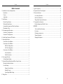
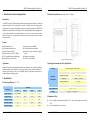
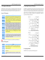
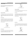
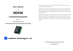
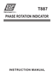
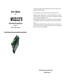
User’s Manual
For
MSD2278
High Performance Microstepping Driver
Version 1.0
©2007All Rights Reserved
The content in this manual has been carefully prepared and is believed to be accurate, but no
responsibility is assumed for inaccuracies.
Motion Control Products reserves the right to make changes without further notice to any
products herein to improve reliability, function or design. Motion Control Products does not assume
any liability arising out of the application or use of any product or circuit described herein; neither does
it convey any license under its patent rights of others.
Motion Control products general policy does not recommend the use of its products in life support
or aircraft applications wherein a failure or malfunction of the product may directly threaten life
or injury.
According to Motion Control Products terms and conditions of sales, the user of Motion Control
products products in life support or aircraft applications assumes all risks of such use and indemnifies
M o t i o n C o n t r o l P r o d u c t s against all damages.
Attention: Please read this manual carefully before using the driver!
©2007 by Motion Control Products Limited.
All Rights Reserved
Contents
Table of contents
1. Introduction, Features and Applications...................................................................... 1
Introduction ............................................................................................................. 1
Features ................................................................................................................... 1
Applications ............................................................................................................ 1
2. Specifications .............................................................................................................. 1
Electrical Specifications .......................................................................................... 1
Mechanical Specifications....................................................................................... 2
Operating Environment and Other Specifications................................................... 2
Elimination of Heat ................................................................................................. 2
3. Pin Assignment and Description ................................................................................. 3
Connector P1 Configurations .................................................................................. 3
Connector P2 Configurations .................................................................................. 3
4. Control Signal Connector (P1) Interface..................................................................... 4
5. Connecting the Motor.................................................................................................. 4
Connections to 4-lead Motors ................................................................................. 5
Connections to 6-lead Motors ................................................................................. 5
Half Coil Configurations ................................................................................. 5
Full Coil Configurations.................................................................................. 5
Connections to 8-lead Motors ................................................................................. 6
Series Connections .......................................................................................... 6
Parallel Connections........................................................................................ 6
6. Power supply Selection ............................................................................................... 7
Selecting Supply Voltage......................................................................................... 7
7. Selecting Microstep Resolution and Driver Output Current ....................................... 7
Microstep Resolution Selection............................................................................... 7
Current Settings....................................................................................................... 8
Dynamic Current Setting................................................................................. 8
Standstill Current............................................................................................. 9
Control Signal Mode Setting ........................................................................... 9
8. Wiring Notes ............................................................................................................... 9
I
Contents
9. Typical Connection.................................................................................................... 10
10. Sequence Chart of Control Signals ......................................................................... 10
11. Protection Functions................................................................................................ 11
Over-voltage Protection ........................................................................................ 11
Short Circuit Protection......................................................................................... 11
Wrong Motor Connection Protection .................................................................... 11
12. Frequently Asked Questions.................................................................................... 11
Problem Symptoms and Possible Causes .............................................................. 12
APPENDIX ................................................................................................................... 13
Twelve month limited warranty............................................................................. 13
Exclusions ............................................................................................................. 13
Obtaining warranty service ................................................................................... 13
Warranty limitations .............................................................................................. 13
Shipping failed product ......................................................................................... 13
II
MSD2278 Microstepping Driver Manual V1.0
1. Introduction, Features and Applications
MSD2278 Microstepping Driver Manual V1.0
Mechanical Specifications (unit: mm, 1 inch = 25.4 mm)
Introduction
The MSD2278 is a high voltage and high performance microstepping driver based on one of the most
advanced technologies in the world today. It’s suitable for driving 2-phase and 4-phase hybrid
stepping motors. By using advanced bipolar constant-current chopping technique, the MSD2278 can
output more torque than other drivers at high speed. The microstep capability allows stepping motors
to run at higher smoothness, less vibration and lower noise. Its 3-state current control technology
allows coil current to be well controlled with relatively small current ripple, therefore less motor
heating is achieved.
Features
l High quality, low price
l Low heating for motor & driver
l Supply voltage up to220VAC
l Output current up to 7.8A(5.57 ARMS)
l TTL compatible and Opto-isolated inputs
l Automatic idle-current reduction
l Input frequency up to 400KHz
l 16 microstep resolutions selectable
l Suitable for 2-phase and 4-phase stepping
motors
l DIP switch current setting
l CW/CCW mode selectable
Applications
Figure 1: Mechanical specifications
Operating Environment and Other Specifications
Suitable for large and medium automation machines and equipments, such as engraving machines,
labeling machines, cutting machines, laser phototypesetting systems, plotting instruments, NC
machines, pick-place devices, and so on. Particularly adapt to the applications desired with low
vibration, high speed and high precision.
Environment
Operating
2. Specifications
Environment
Electrical Specifications (Tj = 25℃)
Parameters
MSD2278
Typical
Max
Unit
Output current
0.42 (0.3A RMS)
-
7.8
A
Supply voltage
80
180
220
VAC
Logic signal current
7
10
16
mA
Pulse input frequency
0
-
400
Khz
Isolation resistance
500
MΩ
1
Avoid dust, oil fog and corrosive gases
Ambient Temperature
0℃ - 50℃
Humidity
40%RH - 90%RH
Operating Temperature
70℃ Max
Vibration
5.9m/s2 Max
-20℃ - 65℃
Storage Temperature
Min
Tel: +44 (0)1202 599922
Natural Cooling or Forced cooling
Cooling
Approx.
Weight
1.16 kg (41 oz)
Elimination of Heat
l
l
Driver’s reliable working temperature should be <65℃, motor working temperature should be
<80℃;
Forced cooling the driver if it’s necessary.
Tel: +44 (0)1202 599922
2
MSD2278 Microstepping Driver Manual V1.0
MSD2278 Microstepping Driver Manual V1.0
3. Pin Assignment and Description
4. Control Signal Connector (P1) Interface
The MSD2278 has two connectors, connector P1 for control signals connections, and connector P2 for
power and motor connections. The following tables are brief descriptions of the two connectors of the
MSD2278. More detailed descriptions of the pins and related issues are presented in section 4, 5, 9.
The MSD2278 can accept differential and single-ended input signals (including open-collector and
PNP output). The MSD2278 has 3 optically isolated logic inputs which are located on connector P1 to
accept line driver control signals. These inputs are isolated to minimize or eliminate electrical noises
coupled onto the drive control signals. Recommend use line driver control signals to increase noise
immunity of the driver in interference environments. In the following figures, connections to
open-collector and PNP signals are illustrated.
Connector P1 Configurations
Pin Function
PUL+(+5V)
PUL-(PUL)
DIR+(+5V)
DIR-(DIR)
ENA+(+5V)
ENA+(ENA)
READY+
READY-
Details
Pulse signal: In single pulse (pulse/direction) mode, this input represents pulse
signal, effective for each rising edge; 4-5V when PUL-HIGH, 0-0.5V when
PUL-LOW. In double pulse mode (pulse/pulse) , this input represents
clockwise (CW) pulse,effective for high level. For reliable response, pulse
width should be longer than 1.2μs. Series connect resistors for current-limiting
when +12V or +24V used.
DIR signal: In single-pulse mode, this signal has low/high voltage levels,
representing two directions of motor rotation; in double-pulse mode (set by
SW5), this signal is counter-clock (CCW) pulse, effective for high level. For
reliable motion response, DIR signal should be ahead of PUL signal by 5μs at
least. 4-5V when DIR-HIGH, 0-0.5V when DIR-LOW. Please note that motion
direction is also related to motor-driver wiring match. Exchanging the
connection of two wires for a coil to the driver will reverse motion direction.
Enable signal: This signal is used for enabling/disabling the driver. High level
for enabling the driver and low level for disabling the driver. Usually left
unconnected (enabled).
Figure 2: Connections to open-collector signal (common-anode)
Alarm signal positive: READY+ is a photocouper output from open-collector
circuit, effectively output when driver operate normally, maximum permitted
input voltage is 30VDC; maximum output current 20mA. It generally can be
serial connected to PLC input terminal.
Alarm signal negative.
Notes: SW5 ON means CW/CCW (pulse/pulse) mode, and SW5 OFF means PUL/DIR mode.
Connector P2 Configurations
Pin Function
AC
AC
A+, AB+, BPE
Details
AC power supply inputs. Recommend use isolation transformers with
theoretical output voltage of +80~+ 180 VAC, leaving room for power
fluctuation and back-EMF.
Motor phase A.
Motor phase B.
Ground terminal. Recommend connect this port to the ground for better
safety.
Tel: +44 (0)1202 599922
3
Figure 3: Connection to PNP signal (common-cathode)
5. Connecting the Motor
The MSD2278 can drive 2-pahse and 4-pahse hybrid stepping motors.
Tel: +44 (0)1202 599922
4
MSD2278 Microstepping Driver Manual V1.0
MSD2278 Microstepping Driver Manual V1.0
Connections to 4-lead Motors
4 lead motors are the least flexible but easiest to wire. Speed and torque will depend on winding
inductance. In setting the driver output current, multiply the specified phase current by 1.4 to
determine the peak output current.
Figure 6: 6-lead motor full coil (higher torque) connections
Connections to 8-lead Motors
Figure 4: 4-lead Motor Connections
8 lead motors offer a high degree of flexibility to the system designer in that they may be connected
in series or parallel, thus satisfying a wide range of applications.
Connections to 6-lead Motors
Series Connections
Like 8 lead stepping motors, 6 lead motors have two configurations available for high speed or high
torque operation. The higher speed configuration, or half coil, is so described because it uses one half
of the motor’s inductor windings. The higher torque configuration, or full coil, uses the full windings
of the phases.
A series motor configuration would typically be used in applications where a higher torque at lower
speeds is required. Because this configuration has the most inductance, the performance will start to
degrade at higher speeds. In series mode, the motors should also be run at only 70% of their rated
current to prevent over heating.
Half Coil Configurations
As previously stated, the half coil configuration uses 50% of the motor phase windings. This gives
lower inductance, hence, lower torque output. Like the parallel connection of 8 lead motor, the torque
output will be more stable at higher speeds. This configuration is also referred to as half chopper. In
setting the driver output current multiply the specified per phase (or unipolar) current rating by 1.4 to
determine the peak output current.
Figure 7: 8-lead motor series connections
Parallel Connections
An 8 lead motor in a parallel configuration offers a more stable, but lower torque at lower speeds. But
because of the lower inductance, there will be higher torque at higher speeds. Multiply the per phase
(or unipolar) current rating by 1.96, or the bipolar current rating by 1.4, to determine the peak output
current.
Figure 5: 6-lead motor half coil (higher speed) connections
Full Coil Configurations
The full coil configuration on a six lead motor should be used in applications where higher torque at
lower speeds is desired. This configuration is also referred to as full copper. In full coil mode, the
motors should be run at only 70% of their rated current to prevent over heating.
Tel: +44 (0) 1202 599922
5
Figure 8: 8-lead motor parallel connections
Tel: +44 (0)1202 599922
6
MSD2278 Microstepping Driver Manual V1.0
6. Power Supply Selection
The MSD2278 can match large and medium size stepping motors (from NEMA size 34 to 43) Supplies
by Motion Control Products or other motor manufactures around the world. To achieve good driving
performances, it is important to select supply voltage and output current properly. Generally speaking,
supply voltage determines the high speed performance of the motor, while output current determines
the output torque of the driven motor (particularly at lower speed).
Attention: For safety and to improve reliability, it is recommended to use isolation transformer
instead of directly use network source to supply the MSD2278. Recommend use isolation transformers
with theoretical output voltage of +80~+ 180VAC, leaving room for power fluctuation and
back-EMF. And the power of the isolation transformer should larger than 500 watts.
Selecting Supply Voltage
The MSD2278 can actually operate within +80V-+220VAC, including power input fluctuation and
back EMF voltage generated by motor coils during motor shaft deceleration. Higher supply voltage
can increase motor torque at higher speeds, thus helpful for avoiding losing steps. However, higher
voltage may cause bigger motor vibration at lower speed, and it may also cause over-voltage
protection or even driver damage. Therefore, it is suggested to choose only sufficiently high supply
voltage for intended applications, and it is suggested to use power supplies with theoretical output
voltage of +80~+ 180 VAC, leaving room for power fluctuation and back-EMF. If the motion speed
requirement is low, it’s better to use lower supply voltage to decrease noise, heating and improve
reliability.
7. Selecting Microstep Resolution and Driver Output Current
This driver uses a 9-bit DIP switch to set microstep resolution, motor operating current and control
signal mode as shown in the following figure:
MSD2278 Microstepping Driver Manual V1.0
Steps/rev.(for 1.8°motor)
400
500
600
800
1000
1200
1600
2000
2400
3200
4000
5000
6000
6400
8000
10000
SW1
ON
OFF
ON
OFF
ON
OFF
ON
OFF
ON
OFF
ON
OFF
ON
OFF
ON
OFF
SW2
ON
ON
OFF
OFF
ON
ON
OFF
OFF
ON
ON
OFF
OFF
ON
ON
OFF
OFF
SW3
ON
ON
ON
ON
OFF
OFF
OFF
OFF
ON
ON
ON
ON
OFF
OFF
OFF
OFF
SW4
ON
ON
ON
ON
ON
ON
ON
ON
OFF
OFF
OFF
OFF
OFF
OFF
OFF
OFF
Current Settings
For a given motor, higher driver current will make the motor to output more torque, but at the same
time causes more heating in the motor and driver. Therefore, output current is generally set to be such
that the motor will not overheat for long time operation. Since parallel and serial connections of
motor coils will significantly change resulting inductance and resistance, it is therefore important to
set driver output current depending on motor phase current, motor leads and connection methods.
Phase current rating supplied by motor manufacturer is important in selecting driver current, however
the selection also depends on leads and connections.
The first three bits (SW6, 7, 8, 9) of the DIP switch are used to set the dynamic current. Select a
setting closest to your motor’s required current.
Dynamic Current Setting
Microstep Resolution Selection
Microstep resolution is set by SW1, 2, 3, 4 of the DIP switch as shown in the following table:
Tel: +44 (0) 1202 599922
7
Peak current (A)
0.45
0.63
1.41
1.88
2.33
2.85
3.23
3.75
RMS (A)
0.32
0.45
1.00
1.34
1.66
2.04
2.31
2.68
Tel: +44 (0) 1202 599922
SW6
OFF
OFF
OFF
OFF
OFF
OFF
OFF
OFF
SW7
OFF
OFF
OFF
OFF
ON
ON
ON
ON
8
SW8
OFF
OFF
ON
ON
OFF
OFF
ON
ON
SW9
OFF
ON
OFF
ON
OFF
ON
OFF
ON
MSD2278 Microstepping Driver Manual V1.0
MSD2278 Microstepping Driver Manual V1.0
4.26
4.65
5.18
5.55
6.15
6.60
7.20
7.80
3.04
3.32
3.70
3.96
4.39
4.71
5.14
5.57
ON
ON
ON
ON
ON
ON
ON
ON
OFF
OFF
OFF
OFF
ON
ON
ON
ON
OFF
OFF
ON
ON
OFF
OFF
ON
ON
OFF
ON
OFF
ON
OFF
ON
OFF
ON
9. Typical Connection
A complete stepping system should include stepping motor, stepping driver, power supply and
controller (pulse generator). A typical connection is shown as figure 9.
Notes: Due to motor inductance, the actual current in the coil may be smaller than the dynamic
current setting, particularly under high speed condition.
Standstill Current
The MSD2278 has automatic idle-current reduction function. The current automatically be reduced to
60% of the selected dynamic current setting 0.2 second after the last pulse. Theoretically, this will
reduce motor heating to 36% (due to P=I2*R) of the original value. If the application needs a different
standstill current, please contact Motion Control Products.
Control Signal Mode Setting
SW5 is used for this purpose. SW5 ON means CW/CCW (pulse/pulse) mode, and SW5 OFF means
PUL/DIR mode.
8. Wiring Notes
Figure 9: Typical connection
10. Sequence Chart of Control Signals
l
In order to improve anti-interference performance of the driver, it is recommended to use
twisted pair shield cable.
l
To prevent noise incurred in pulse/dir signal, pulse/direction signal wires and motor wires
should not be tied up together. It is better to separate them by at least 10 cm, otherwise the
disturbing signals generated by motor will easily disturb pulse direction signals, causing motor
position error, system instability and other failures.
l
If a power supply serves several drivers, separately connecting the drivers is recommended
instead of daisy-chaining.
l
It is prohibited to pull and plug connector P2 while the driver is powered ON, because there is
high current flowing through motor coils (even when motor is at standstill). Pulling or plugging
connector P2 with power on will cause extremely high back-EMF voltage surge, which may
damage the driver.
In order to avoid some fault operations and deviations, PUL, DIR and ENA signals should abide by
some rules, shown as following diagram:
Figure 11: Sequence chart of control signals
Tel: +44 (0) 1202 599922
9
Tel: +44 (0) 1202 599922
10
MSD2278 Microstepping Driver Manual V1.0
Remark:
(1)
MSD2278 Microstepping Driver Manual V1.0
Problem Symptoms and Possible Causes
t1: ENA must be ahead of DIR by at least 5μs, logic HIGH as effective. Generally ENA+
and ENA- is NC (not connected).
(2)
t2: DIR must be ahead of PUL effective edge by at least 5μs to ensure correct direction;
(3)
t3: Pulse width not less than 1.2μs;
(4)
t4: Low level width not less than 1.2μs.
Symptoms
Possible Problems
No power
Microstep resolution setting is wrong
Motor is not rotating
DIP switch current setting is wrong
Fault condition exists
11. Protection Functions
The driver is disabled
To improve reliability, the driver incorporates some built-in protection features.
Motor phases may be connected in reverse
Motor rotates in the wrong direction
DIP switch current setting is wrong
The driver in fault
Over-voltage Protection
Something wrong with motor coil
Control signal is too weak
When power supply voltage exceeds +250VAC, protection will be activated and LED will turn red.
When power supply voltage is lower than +80VAC, the driver will not works properly.
Control signal is interfered
Erratic motor motion
Short Circuit Protection
Wrong motor connection
Something wrong with motor coil
Protection will be activated in case of short circuit between motor coils or between motor coil and ground.
Current setting is too small, losing steps
Wrong Motor Connection Protection
Protection will be activated when the motor is connected in a wrong way.
Current setting is too small
Motor is undersized for the application
Motor stalls during acceleration
Acceleration is set too high
When above protections are active, the motor shaft will be free or the LED will turn red. Reset the
driver by repowering it to make it function properly after removing above problems.
12. Frequently Asked Questions
Power supply voltage too low
Inadequate heat sinking / cooling
Excessive motor and driver heating
Automatic current reduction function not being utilized
Current is set too high
In the event that your MSD2278 doesn’t operate properly, the first step is to identify whether the
problem is electrical or mechanical in nature. The next step is to isolate the system component that is
causing the problem. As part of this process you may have to disconnect the individual components
that make up your system and verify that they operate independently. It is important to document
each step in the troubleshooting process. You may need this documentation to refer back to at a later
date, and these details will greatly assist our Technical Support staff in determining the problem
should you need assistance.
Many of the problems that affect motion control systems can be traced to electrical noise, controller
software errors, or mistake in wiring.
Tel: +44 (0) 1202 599922
11
Tel: +44 (0) 1202 599922
12
MSD2278 Microstepping Driver Manual V1.0
APPENDIX
Twelve Month Limited Warranty
Motion Control Products Ltd. warrants its products against defects in materials and
workmanship for a period of 12 months from shipment out of factory. During the warranty period,
Motion Control Products will either, at its option, repair or replace products which proved to be defective.
Exclusions
The above warranty does not extend to any product damaged by reasons of improper or inadequate
handlings by customer, improper or inadequate customer wirings, unauthorized modification or
misuse, or operation beyond the electrical specifications of the product and/or operation beyond
environmental specifications for the product.
Obtaining Warranty Service
To obtain warranty service, a returned material authorization number (RMA) must be obtained
from our website at www.motioncontrolproducts.com/returns.html.
Customer shall prepay shipping charges for products returned to Motion ControlProducts for
warranty service, and Motion Control Products shall pay for return of products to customer.
Warranty Limitations
Motion Control Products makes no other warranty, either expressed or implied, with respect to the
product. Motion Control Products specifically disclaims the implied warranties of merchantability and
fitness for a particular purpose. Some jurisdictions do not allow limitations on how long and implied warranty
lasts, so the above limitation or exclusion may not apply to you. However, any implied warranty of merchantability
or fitness is limited to the 12-month duration of this written warranty.
Tel: +44 (0) 1202 599922
13