1
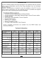
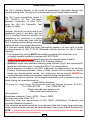
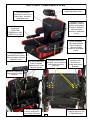
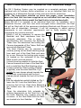
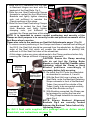
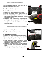
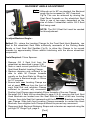
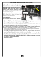
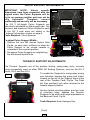
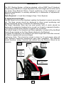
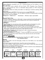
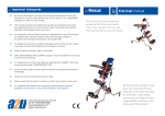
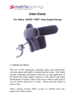
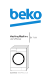
2 Seating System Installation and User Manual For use with the Invacare Action Range of Wheelchairs (July 2014 Edition 2) Seating Systems Contents Introduction .................................................... 4 Technical Data ................................................ 4 Safety Guidelines ............................................ 5 Transportation information .............................. 6 Gill 2 Seat Components Plan .......................... 7 Initial Installation (Action Range) ..................... 8-9 Gill 2—Action Range Package ......................... 10 Seat Depth Adjustment .................................... 11 Backrest Height Adjustment ............................. 11 Backrest Angle Adjustment .............................. 12-13 Pelvic Support Adjustment ............................... 14 Thoracic Support Adjustment ........................... 14-15 Headrest Adjustment ........................................ 16 Upholstery and Cleaning ................................... 17 Warranty Statement ........................................... 18 Product Maintenance ......................................... 18 Product Serial Numbers ..................................... 19 The Gill 2 Seating System is the result of experienced, thoughtful design and rigorous in-house testing, field trials and frontal impact testing, over 12 months. Many adjustable features have been built into the Gill 2, enabling it to become an extremely versatile seating system, available in four sizes. RMS Ltd, reserves the right to change without notice, the design, methods of manufacture, or raw materials used in the construction of the Gill 2 Seating System, where it considers such changes will serve to improve the product quality, or become necessary to meet any changes in device legislation. Should the reader have any concerns regarding the installation, set-up, adjustments, or use of the Gill 2 Seating System, please contact the RMS Ltd Technical Help-line on 01795 477280. 3 INTRODUCTION The Gill 2 Seating System has been developed to be interfaced with the Invacare Action range of wheelchairs and the Neo tilting wheelbase from the Southwest Seating Company. However, this publication is intended to cover the installation of the Gill 2 into the Action range of wheelchairs only, as a separate manual is available and supplied with the Gill 2 when interfacing with the Neo wheelbase. The Standard Gill 2 consists of: One piece modular seating system including interface. Growth adjustment in Seat depth, Backrest height, Hip and Thoracic widths. Padded Lap Belt. Swing-away, width adjustable, Thoracic Supports. Ramped Seat Cushion. RMS Type “D” Headrest. Machine Washable Covers. Full length, width adjustable, Pelvic Supports. Further compatible accessories are available from the RMS Product and Accessory Catalogue. Technical Information Gill 2 Seating System Size Guide Size 1 Gill2-1-01-00 Size 2 Gill2-2-01-00 Size 3 Gill2-3-01-00 Size 4 Gill2-4-01-00 Pelvic Width Min / Max 200mm / 275mm 250mm / 325mm 315mm / 375mm 365mm / 425mm Seat Depth Min / Max 225mm / 300mm 300mm / 375mm 360mm / 435mm 430mm / 505mm Backrest Height Min / Max 355mm / 430mm 390mm / 465mm 450mm / 525mm 500mm / 575mm 88mm x 138mm 98mm x 168mm 108mm x 188mm 100mm x 325mm 100mm x 400mm 100mm x 475mm Thoracic Pad size H x L 78mm x 113mm Pelvic Pad size H x L 75mm x 275mm Seat Ramp Length 145mm 170mm 180mm 190mm Weight capacity for Transportation 50Kg 50Kg 50Kg 50Kg Max Weight capacity 80Kg 80Kg 80Kg 80Kg Seat Unit Weight 6Kg 7.8Kg 9.3Kg 10.9Kg Action 3 NG Junior 13 x 11 Action 3 NG Junior 15 x 13 Action 3 NG 17 x 16 Action 4 NG 19 x 18 Recommended Surrogate Wheelchair 4 SAFETY GUIDELINES Due to the various activities that a wheelchair user has to perform, RMS Ltd recommends that, prior to issuing the GILL 2 Seating System and the wheelchair into which it is to be interfaced, this manual, together with any wheelchair manufacturer’ User Guide, should be studied by all relevant persons, to ensure that all instructions, procedures and warnings are carefully observed and understood. For correct support and user comfort, it is strongly recommended that the initial installation, any adjustments and final hand-over are carried out by a suitably qualified person. The maximum occupant capacity of a complete GILL 2 Seating System for transportation purposes, when interfaced into a wheelchair with a seat width up to 19”, is 50Kg (7.8 stones). As the installation of a GILL 2 System may raise or position the user further forward in their wheelchair, an appropriate stability test should be carried out prior to final commissioning. After the GILL 2 Seating System has been initially adjusted to suit the individual user, any settings should not be affected subsequently, by the removal and refitting of the Seat Unit to allow the wheelchair to be folded. However, care should be taken not to impact adjustable components whilst the Seat Unit is removed from the wheelchair, as this could affect their original preset position. To accommodate any changes in user growth or postural positioning, it is recommended that the user be checked at regular intervals by a suitably qualified person, to ensure that adjustable components are correctly set to suit the user’s current requirements. Carers should ensure correct utilisation of any positioning Straps or Harnesses, as failure to do so could result in injury to the user. It is recommended that any Postural Straps or Harnesses being used, are the first items to be secured when the user enters the seat and the last items to be released before exiting. Worn or damaged upholstery can lead to hygiene contamination, cause injury to the user and, in some cases, fail to support the user correctly. Regular inspections of all upholstery should be made and any defects should be reported to the relevant authority for rectification as soon as possible. Ancillary devices, such as the Headrest, positioning Straps and Harnesses, Kneeblock or Pommel should be checked for security and positioning on a daily basis. The wheelchair parking brakes should always be applied before attempting to transfer the occupant, removing or refitting the GILL 2 System or making any adjustments. Never hang heavy objects on the GILL 2 Seating System or any part of the wheelchair, as this could seriously affect the overall wheelchair stability. Any reference to Left or Right in this manual, will refer to the Left or Right side when sitting forward facing in the Seat Unit. 5 TRANSPORTATION The Gill 2 Seating System is the result of experienced, thoughtful design and rigorous testing over 12 months of in-house testing and frontal impact testing. The Gill 2 was successfully tested to ISO 16840-4 at the Transport Research Laboratory in May 2013, using the HIII 5th Percentile Test Dummy to 49Kg. However, this does not imply and is not intended to imply in any way, that the GILL 2 Seating System is suitable for transporting an occupant in a motor vehicle in any other way than with the GILL 2 Seating System being correctly interfaced with a surrogate wheelchair of a type and model which has been successfully tested in its own right, to meet the requirements of ISO 7176-19 (Wheeled mobility devices for use in Motor Vehicles). The transporting vehicle MUST be suitably equipped with wheelchair and occupant restraint systems compliant with ISO 10542. Under No Circumstances should any part of a transportation restraint system, be attached directly to the GILL 2 Seating System. ALWAYS check both backrest retaining strap buckles (Fig.4) are connected & tensioned sufficiently prior to using the GILL 2 on transportation. Whilst provision is made on the GILL 2 Backrest for attachment of an ancillary Postural Positioning Harness, which, if fitted, should still be utilised as normal during any transportation period, this positioning device should NEVER be used as the sole method of occupant restraint during transportation. The restraint systems used for the surrogate wheelbase and occupant during the above testing, are manufactured by:Unwin Safety Systems. C.N. Unwin Ltd., Unwin House, The Horseshoe, Coat Road, Martock, Somerset, TA12 6EY. Tel: 01935 827740 Fax: 01935 827760 Email: [email protected] Web: www.unwin-safety.com Part numbers:Wheelbase restraints: Front—OF03 Rear—OR02 Occupant restraints: Static 3PT These kits meet the requirements of ISO 10542, (Wheelchair Tie-downs and Occupant Restraint Systems). If the intended transporting vehicle is not already fitted with Unwin type anchorage tracks, details of these can also be obtained direct from Unwin Safety Systems Ltd NOTE: Installation and use of all restraint systems should always be strictly as per their manufacturers recommendations. 6 GILL 2 SEAT COMPONENTS PLAN RMS Type “D” Headrest with angle-adjustable Stem. Fully Upholstered Backrest Cushion with removable, machinewashable cover. Height and width adjustable, positive locking, swing-away Thoracic Supports, with removable machine- washable covers. RMS Padded, Single-pull, Pelvic Belt PB009 sizes 1&2 PB007 sizes 3&4 Width adjustable full-length Padded Pelvic Supports, with removable machine- washable covers. Fully Upholstered Ramped Seat Cushion with removable machinewashable cover. Interface Seat Hook Brackets, with pre-drilled alternative mounting positions. Pre-drilled Backrest Panel to enable attachment of upper Harness Straps. Hayden Clamps installed onto Seat Rails to locate Seat Hook Brackets Backrest Retaining Straps with Pull-tight Buckles Extended Backrest Cushion to allow for use of Back Extension 7 Extended Seat Cushion allow for use of Seat Extension GILL 2 Initial Installation—Invacare ACTION Wheelchair Range The Gill 2 Seating System may be supplied as a complete package, already interfaced with its Invacare Action wheelchair, or as an individual Seat Unit, for installation by a Wheelchair Service to their own stock Action wheelchair. NOTE: The instructions detailed on these two pages, cover installation where the Seat Unit has been supplied as an individual Unit and may vary according to which Action model the Seat Unit is to be interfaced with. Where the Gill 2 is supplied as an individual Seat Unit, for installation via a Wheelchair Service, onto their own stock surrogate Action wheelchair, the Seat Unit will be fitted with all the necessary interfacing Brackets and Straps to suit a specific size of wheelchair. However, it will be necessary to adjust various components to suit individual requirements and to finally ensure that all components are correctly secured. Fig.1 Seat Hook 1. Initially it will be necessary to remove the Bracket Backrest and Seat canvasses from the Locating Clamps surrogate wheelchair. This is done by disconnecting and removing the Backrest Tubes from the wheelchair and sliding the Seat Hook Canvas downwards off the Tubes. Refit and Bracket Locating Clamps secure both Backrest Tubes. 2. The Seat Canvas can be removed by carefully prizing out the black blanking plugs from each end of the Seat Rails and save for re-use. Remove the locking grub screws (4) located on the underside of the Seat Rails at each end and discard. It should now be possible to slide the Seat Canvas forwards and clear of the Seat Rails and re-install the Seat Rail blanking plugs. 3. Loosely install two Seat Locating Clamps Fig.2 (supplied), onto the each Seat Rail, Fig.1. Initially the rear clamps placed towards the Wheelchair cross braces and the front clamps placed towards the front of the Seat Rails. 4. With the wheelchair partially folded as Fig.1, lower the Gill 2 onto the Seat Rails, Fig.2, ensuring that all four Seat Hook Brackets are located over the outside of the Seat Rails. 5. Open the wheelchair fully outwards by pushing downwards on the Seat Unit until the Hook Brackets fully engage over the curvature of the Seat Rails and the Rails are located into their Saddles. [Cont] 8 6. Move the Gill 2 rearwards until the Seat Fig.3 to Backrest Hinges are level with the backend of the Seat Rails. Fig.3. 7. Slide the rear Seat Positioning Clamps forwards to contact the front Seat Hook Brackets and lightly tighten clamping nuts, just sufficient to maintain the Clamp positions at this stage. 8. Slide the front Seat Positioning Clamps rearwards to contact the front Seat Hook Brackets and lightly tighten clamping nuts, just sufficient to maintain the Clamp positions at this stage. NOTE: It is important to ensure correct positioning and security of the Clamps as their purpose is to correctly locate and prevent movement of the Seat Base when in service. Please also refer to the sections on Seat Unit Adjustments pages 11 to 16. 9. To ensure correct positioning of the Clamps and ease of removal and refitting of the Gill 2, the Seat Unit should be removed from the wheelchair, by lifting both sides of the Seat Unit which will enable the wheelchair to partially fold, sufficient to lift the Seat Unit clear of the wheelchair. At this stage, make any minor adjustments to the Clamp positions before fully securing the Clamps sufficient to prevent any movement. CAUTION: Ensure the Clamp securing Fig.4 nuts do not foul the Parking Brake Mounts or front Seat Rail Saddles when tightening, adjust the Clamp or Hook Backrest Alignment Bracket positions accordingly if Brackets necessary before fully securing. 10. Re-install the Gill 2 onto the wheelchair Backrest as described in sections 4, 5 and 6. Retaining Strap Main Buckles 11. With the Seat Unit now in place on the Seat Rails, route the Backrest Retaining Straps outwards in front of the Backrest Tubes, then around the outside of the Tubes, finally to be connected centrally by the Main Buckles as Fig.4. Pull-tight 12. With Buckles connected, the Straps can Straps with be tensioned by pulling the free-end “D” Rings “D” Ring Straps outwards to remove any slack.Fig.4 NOTE: Ensure Backrest Alignment Brackets Fig.4 are correctly located between the Backrest Tubes before fully tightening Straps. For Gill 2 Seat units supplied as a package with an Action model wheelchair, see instructions on page 10. 9 GILL 2—ACTION Range PACKAGE Where the Gill 2 is supplied by RMS Ltd, together with an appropriate size Action wheelchair, as a package, the wheelchair will have the Seat and Backrest Canvasses removed and the Gill 2 Seat Hook Bracket Locating Clamps already installed to accept the Seat Unit Seat. 1. After unpacking the Action wheelchair and Gill 2 Seat Unit, position the wheelchair on a suitable surface and apply both parking brakes. 2. Open the wheelchair outwards to just over half way as Fig.1 page 8. 3. With the Gill 2 Backrest in the upright position, lift the Seat Unit on to the wheelchair, by firstly engaging both Hook Brackets on one side, over the wheelchair Seat Rail, ensuring that the front Hook Bracket locates between the Locating Clamps on that side, Fig.2 page 8, then lowering the Seat Unit onto the opposite Seat Rail. 4. By pushing downwards on both sides of the Seat Unit, the wheelchair should open out to enable all four Seat Hook Brackets to fully engage over each wheelchair Seat Rail, with both front Hook Brackets engaging between their Locating Clamps. 5. With the Seat Unit now in place on the Seat Rails, route the Backrest Retaining Straps outwards in front of the Backrest Tubes, then around the outside of the Tubes, finally to be connected centrally by the Main Buckles as Fig.4 page 9. 6. With the Main Buckles connected, the Straps can now be tensioned by pulling the free end “D” ring Straps outwards to remove any slack Fig.4 page 9. NOTES: Ensure Backrest Alignment Brackets Fig.4 are correctly located between the Backrest Tubes before fully tightening both Seat Unit securing Straps. If dimensions such as Seat Depth, Backrest Height, Backrest Angle, Pelvic Width or Thoracic Width and Height were stated at the time of order, these will be factory set by RMS prior to despatch. Some minor adjustments may be necessary to suit any possible changes in client requirements. Please refer to the following pages for adjustments. 10 SEAT DEPTH ADJUSTMENT From the standard position, Seat Depth can be Fig.5a extended forwards by up to 75mm. Tools Required: 10mm Spanner To adjust Seat Depth:M6 Domed 1. Remove the Velcro attached Seat Cushion. Nuts 2. Slacken the domed Nylock Nuts securing the front Pelvic Support Brackets Fig.5a. 3. Slide Seat Depth Adjustment Panel forwards to Fig.5b the required position and retighten the domed Nylock Nuts Fig.5b. 4. Re-attach Seat Cushion with front edge just overlapping the newly positioned Adjustment Panel. The Cushion is designed to be long enough to cover the Seat Panel when set to Adjustment Panel maximum length. BACKREST HEIGHT ADJUSTMENT From the standard position, the Backrest height is adjustable upwards by 75mm. Fig.6a M6 Hex. Drive Screws Tools Required: 4mm Hexagon Key To adjust Backrest Height:1. Remove the Velcro attached Backrest Cushion. 2. Using the 4mm Hexagon Key, slacken the M6 Hex. Head Screws securing the Backrest Extension Panel, Fig.6a. 3. Slide Backrest Height Adjustment Panel Fig.6b upwards to the required position and retighten the M6 Hex. Head Screws, Fig.6b. 4. Re-attach Backrest Cushion with top edge just level with the newly positioned Adjustment Panel. The Cushion is designed to be long enough to cover the Backrest Panel when set to maximum. 11 Adjustment Panel BACKREST ANGLE ADJUSTMENT Fig.7a Although set to 90º as standard, the Backrest angle can be increased to 100º if required, Fig.7a This can be achieved by moving the Seat Panel forwards on the wheelchair Seat Rails in one of two ways, dependant on the size of Action 3 wheelchair and/or Gill 2 Seat Unit being used. 90° 100° NOTE: The Gill 2 Seat Unit must be vacated for this adjustment. To adjust Backrest Angle:Method (1) - where the Locating Clamps for the Front Seat Hook Brackets, are fitted to the wheelchair Seat Rails sufficiently rearwards of the Parking Brake Mounts or front Seat Rail Saddles Fig.7b, to allow the Clamps to be moved forwards by approximately 50mm without interfering with the above wheelchair components. Tools Required: 13mm Spanner. Fig.7b 1. Remove Gill 2 Seat Unit from the wheelchair as described in page 9 (9). 2. Note or mark current positions of Front Seat Hook Bracket Locating Clamps. 3. Slacken clamping nuts sufficient to be able to slide all Clamps forwards equally on the Seat Rails by 25mm for 5º increase in Backrest angle, or 50mm for 10º increase. 4. Ensure both rear Locating Clamps are Seat Rail set at equal distance from the front of each Seat Rail and retighten Clamps sufficient to prevent any movement. Position front Clamps approximately 30mm forwards of the rear Clamps. 5. Re-install Gill 2 Seat Unit as described in page 8 (4-5), ensuring the front Seat Hook Brackets are located over the Seat Rails in front of the rear Locating Clamps, then slide Seat Unit rearwards until the front Hook Brackets contact the rear Clamps. Slide both front Locating Clamps rearwards to contact the Hook Brackets, then retighten both Clamps sufficient to prevent any movement. 6. Reconnect both Backrest Retaining Straps and re-tension as required using the pull-tight “D” Rings Fig.4, page 9. [Cont] 12 BACKREST ANGLE ADJUSTMENT (cont) Method (2) - is where the Locating Fig.7c Clamps for the front Seat Hook Brackets are already fitted towards the front end of wheelchair Seat Rails, just clear of the Parking Brake Mounts and front Seat Rail Saddles and therefore unable to be moved forwards. Fig.7c. Seat Hook Bracket NOTE: The Gill 2 Seat Unit must be vacated for this adjustment. Tools Required: 4mm Hexagon Key and 10mm Spanner. 1. Remove Gill 2 from wheelchair and remove Seat Cushion. 2. Remove nuts and screws from both front Pelvic Support Brackets and remove the Seat Depth Adjustment Panel, refer to Figs.5 & 6. 3. Disconnect and remove each front Seat Hook Bracket and relocate to either one or two holes rearwards on the Seat Panel, see page 7. NOTE: Moving the Hook Brackets rearwards by one hole will change the Backrest angle to 95º whereas moving two holes will achieve the 100º angle. Fig.7a. 4. Ensure both Hook Brackets are level across the Seat and retighten the domed securing nuts, sufficient to prevent any movement. 5. Re-install Seat Depth Adjustment Panel, set to the required depth and secure, ensuring Pelvic Supports are also set to the required width. 6. Re-install Gill 2 Seat Unit, as described on page 8 (4-5), ensuring the Seat Hook Brackets are located correctly over the Seat Rails. 7. Reconnect both Backrest Retaining Straps and re-tension as required, using the pull-tight “D” Rings Fig.4, page 9. 8. Refit Seat Cushion. 13 PELVIC SUPPORT ADJUSTMENTS IMPORTANT NOTE: Unless specific Fig.8a dimensions have been requested with the original order, the Pelvic Supports will be set to an average position and may not be fully tightened. Therefore, correct positioning and security will be necessary. The Gill 2 full-length Pelvic Supports are individually adjustable by 55mm each side. The minimum and maximum Pelvic Widths for each of the Gill 2 seat sizes are stated in the Technical Information section on page 4. Tools Required: 10mm Spanner M6 Domed Nylock Nuts Fig.8b To adjust Pelvic Support Width:1. Slacken the two M6 domed Nylock Nuts Fig.8a, on each side, sufficient to allow the Pelvic Support to be moved inwards or outwards to the required position. 2. Re-secure Pelvic Supports by retightening the M6 domed Nylock Nuts. Support Brackets THORACIC SUPPORT ADJUSTMENTS The Thoracic Supports are of the positive locking, swing-away style, currently being successfully used on other RMS Gill Seating Systems, such as the Gill 3 Junior, Gill 3 and the Gill 4. To enable the Supports to swing-away during Fig.9a user transfers, depress the green lock button located on the top of the Support Arms at the rear of the Thoracic Pads, Fig.9a. The Pads Swing-away lock buttons will then positively lock when returned to the forward support position. Having slotted mounting plates and two lines of mounting holes, enables the Thoracic Supports to be width and height adjustable on the Backrest Panel. Fig.9b Tools Required: 4mm Hexagon Key [Cont] 14 IMPORTANT NOTE: Unless specific dimensions have been requested with the original order, the Thoracic Supports will be set to an average position and may not be fully tightened. Therefore, correct positioning and security will be necessary. To adjust Thoracic Pad Height:1. To raise or lower the Thoracic Supports, remove the Velcro attached Backrest Cushion from the Backrest Panel. 2. Using the 4mm Hexagon Key, remove the two M6 Hex. Head Mounting Screws Fig.8b, securing the Thoracic Supports to the Backrest Panel. (NOTE: Retain screws and key washers). Fig.9b 3. Move Thoracic Support to the required Alternative Mounting Positions Height, in line with the nearest mounting holes in the Backrest Panel. NOTE: Mounting holes have 25mm centres vertically and 50mm centres laterally. 4. Whilst holding the Thoracic Support, together with the two key washers, in the required position on the front face of the Backrest Panel, insert each retaining screw through the appropriate hole in the Backrest Panel and screw into the key washers, ensuring that the key washers are correctly located in the Thoracic Support Mounting Brackets. (DO NOT FULLY TIGHTEN at this stage). 5. Repeat the above for the opposite side. Thoracic Support Mounting Screws Adjust Thoracic Pad Width as detailed below. To adjust Thoracic Pad Width:NOTE: It will not be necessary to carry out operations 1—5, when adjusting the width only. 6. To obtain the required Thoracic Support width, slacken both Mounting Screws for each Support Fig.9b, using the 4mm Hexagon Key. Slide the Mounting Brackets inwards or outwards, along their key washers, to the required position. Whilst holding the Pads in the upright position, fully re-tighten all screws sufficient to prevent any movement. 7. After completing any adjustments, ensure all screws are fully tightened sufficient to prevent any movement. Re-attach the Backrest Cushion via the Velcro panels. 15 HEADRESTS The Gill 2 Seating System, is fitted as standard, with an RMS Type D Headrest, incorporating a Ball Mount, Angle Adjustable Stem with height pre-set collar and a two screw fixing Backrest Mount. Correct positioning of the Headrest to suit individual requirements, is normally achieved by a combination of adjustments. Refer to Fig.10 Tools Required: 3, 4 and 5mm Hexagon Keys. 13mm Spanner. To adjust Headrest Height:The Ball Mount built into the Headrest, enables the Headrest to swivel around the ball. The three screws should be slackened to allow correct positioning and always retightened evenly to maintain the Headrest position. The Angle Adjustable Stem has two pivot points, both of which should be slackened to enable the Headrest to be moved in a forward or rearward direction. Fully tighten both M8 nuts sufficient to prevent any movement. The overall height of the Headrest and Stem assembly, is locked-off by the Black Thumb Screw located on the Stem Mount attached to the Backrest. To enable the Headrest to be refitted to the same height each time after removal, the Stem is supplied with a pre-set Height Positioning Collar. This should be locked in place by it’s grub-screw, when all other Headrest positioning adjustments have been completed. The Headrest should therefore, always removed and refitted from the Receiver Mount as an assembly. Fig.10 RMS Type “D” Headrest Ball Mount Pre-set Height Positioning Collar Angle Adjustable Stem Locking Thumb Screw Headrest Stem Receiver Mount 16 UPHOLSTERY Unless otherwise requested, your Gill 2 Seating System will be finished in twotone upholstery. The main base colour material, will be of black 100% Polyester, 3mm “Spacer” fabric, complemented by colour co-ordinated edging panels of 100% Polyester Agua Libra fabric. All upholstery items are easily removable, for cleaning or machine washing. Both fabrics are:Flame Retardant to BS5852 Crib 5 and meet or exceed BSEN1021. Anti-Bacterial / Anti Fungal i.e. will not support microbial or fungal growth including Salmonella, E Coli and MRSA. Waterproof — Water or oil Breathable — Moisture vapour permeable. General Fabric Care Use of a vacuum cleaner or soft brush, to remove dust and small solid particles, together with frequent wiping with a damp cloth, will to help to maintain the appearance of the fabrics. Spillages should always be removed as quickly as possible with an absorbent dry cloth. Minor Soiling can normally be removed with a clean damp cloth. Water Based Stains can be cleaned using mild liquid detergent with warm water. Cold water should be use for stains produced by bodily fluids, then rinsed Thoroughly. Followed by drying with a clean absorbent cloth. Light Steam Cleaning can be carried out in situ, ensure all areas are completely dry before reuse. Machine Washing with care @ 40°. Covers must NOT be turned inside-out and any zips should be fully closed. Remove from machine as soon as the wash cycle has finished. DO NOT DRY CLEAN Line Dry ideally the upholstery should be “Line Dried” do NOT Tumble Dry. See Symbols below. NOTES: All soap residue must be thoroughly rinsed out of all fabrics, as it can attract further stains. All stains caused by bodily fluids, should be removed immediately. As with all fabrics, stains that are left in situ for over 24 hours will have set and will become increasingly difficult to remove. Always pre-test cleaners on a hidden area of fabric to test for colour-fastness and texture before proceeding with cleaning. Wash at 40° Cent. Line Dry Iron at MED Temp Do NOT Tumble Dry 17 Do NOT Bleach Do NOT Dry Clean WARRANTY STATEMENT Every effort is made by RMS Ltd., to ensure that your GILL 2 Seating System is manufactured to the highest standards and supplied to the specifications as detailed on the initial prescription / order. The supply of our quality products is backed by the company’s ISO 9001 –2008 Quality Management System and CE Marking declaration. The GILL 2 Seating System is supplied with a manufacturer’s warranty covering faulty materials or workmanship, for a period of twelve months from the date of despatch from our factory. In the unlikely event of a warranty claim being necessary, the failed part must be returned to the manufacturer, or the manufacturer’s approved repairer, for inspection. The failed part may then be repaired or replaced at the manufacturer’s discretion or that of their approved repairer. In the latter case, any displaced parts must be returned to the manufacturer for inspection. Any part, component or accessory, repaired or replaced during the twelve month warranty period, will continue to be covered for the balance of the warranty period only. As unusually high rates of wear on this device, or its ancillary parts, may be caused by the user’s clinical condition, the manufacturer may consider this to be beyond its control. Therefore, items such as Upholstery may only be considered for repair or replacement under the terms of the product warranty, where a failure is clearly attributed to a manufacturing or material defect. With the exception of modifications and / or alterations carried out by the manufacturer, to meet the clinical needs of the user, any attempt to change the design or modify the construction of the GILL 2 Seating System in any way, without prior written authorisation from RMS Ltd, will invalidate the product warranty and the manufacturer’s CE marking declaration. For assistance with any matters relating to the product warranty or for technical information, please contact the RMS Technical Help-line on 01795 477280. PRODUCT MAINTENANCE For safety and security reasons, RMS Ltd recommends that all external components such as the Seat Interface, Backrest Mounting, Headrest Mounting, Pelvic Support Mountings, Thoracic Support Mountings and Pommel Mountings are checked for security at regular intervals. Inspection frequency should be increased accordingly for heavy users. Any defects should be reported to the appropriate authority, with any repairs being carried out by a suitably qualified person, using genuine original equipment replacement parts, available direct from RMS Sales. For assistance with any technical information relating to the Gill 2 Seating System, please contact our Technical Helpline on 01795 477280. 18 GENERAL INFORMATION RECORD Your GILL 2 Seating System Serial Number is: ………………......……… Wheelchair Model and Serial Number .................................................... Date of Supply: ……………………… Supplied to: ………………………………………………………………. ………………………………………………………………. .……………………………………………………………… NOTES 19 Seating Systems Manufactured By THOMPSON HOUSE Unit 10, Styles Close, Sittingbourne, Kent, ME10 3BF Tel: 01795 477280 Fax: 01795 229692 E-mail: [email protected] Web: www.ineedawheelchair.co.uk