1
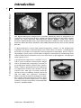
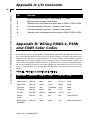
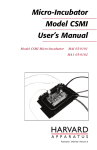
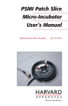
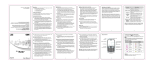
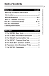
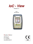
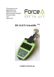
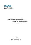
Model TC-202A
Bipolar/Monopolar
Temperature Controller
User's Manual
Model TC-202A Bipolar/Monopolar Temp. Controller MA1 65-0045
Model TC-202AM Bipolar/Monopolar Temp. Controller MA1 65-0046
Publication 5403-008-REV-C
WEEE/RoHS Compliance Statement
EU Directives WEEE and RoHS
To Our Valued Customers:
We are committed to being a good corporate citizen. As part of that commitment,
we strive to maintain an environmentally conscious manufacturing operation. The
European Union (EU) has enacted two Directives, the first on product recycling
(Waste Electrical and Electronic Equipment, WEEE) and the second limiting the use
of certain substances (Restriction on the use of Hazardous Substances, RoHS).
Over time, these Directives will be implemented in the national laws of each EU
Member State.
Once the final national regulations have been put into place, recycling will be offered
for our products which are within the scope of the WEEE Directive. Products falling
under the scope of the WEEE Directive available for sale after August 13, 2005 will
be identified with a “wheelie bin” symbol.
Two Categories of products covered by the WEEE Directive are currently exempt
from the RoHS Directive – Category 8, medical devices (with the exception of
implanted or infected products) and Category 9, monitoring and control instruments.
Most of our products fall into either Category 8 or 9 and are currently exempt from
the RoHS Directive. We will continue to monitor the application of the RoHS
Directive to its products and will comply with any changes as they apply.
• Do Not Dispose Product with Municipal Waste
• Special Collection/Disposal Required
Table of Contents
Harvard Apparatus TC-202A Bipolar/Monopolar Temperature Controller User's Manual
1
SUBJECT
PAGE NO.
Warranty and Repair Information ........................2
Specifications ........................................................3
Introduction ........................................................4-5
Setting Up the TC-202A ........................................6
Front Panel Connectors and Controls ................7
Operation ................................................................8
Troubleshooting ....................................................9
Appendices:
Appendix A: I/O Connectors ............................10
Appendix B: PDMI-2/PSMI/CSMI
Wiring Color Codes ..........................................10
Appendix C: Voltage and Fuse Settings ..........11
Appendix D: Rack Mounting the TC-202A ......12
Publication 5403-008-REV-C
Warranty and Repair Information
2
Harvard Apparatus TC-202A Bipolar/Monopolar Temperature Controller User's Manual
Serial Numbers
All inquires concerning our product should refer to the serial number of the unit.
Serial numbers are located on the rear of the chassis.
Calibrations
All electrical apparatus is calibrated at rated voltage and frequency.
Wa rr a n t y
Harvard Apparatus warranties this instrument for a period of one year from date of
purchase.At its option, Harvard Apparatus will repair or replace the unit if it is found
to be defective as to workmanship or material.
This warranty does not extend to damage resulting from misuse, neglect or abuse, normal wear and tear, or accident.
This warranty extends only to the original customer purchaser.
IN NO EVENT SHALL HARVARD APPARATUS BE LIABLE FOR INCIDENTAL OR
CONSEQUENTIAL DAMAGES. Some states do not allow exclusion or limitation of
incidental or consequential damages so the above limitation or exclusion may not
apply to you. THERE ARE NO IMPLIED WARRANTIES OF MERCHANTABILITY,
OR FITNESS FOR A PARTICULAR USE, OR OF ANY OTHER NATURE. Some states
do not allow this limitation on an implied warranty, so the above limitation may not
apply to you.
If a defect arises within the one-year warranty period, promptly contact Harvard
Apparatus, Inc. 84 October Hill Road, Building 7, Holliston, Massachusetts
01746-1371 using our toll free number 1-800-272-2775. Goods will not be accepted
for return unless an RMA (returned materials authorization) number has been issued
by our customer service department. The customer is responsible for shipping
charges. Please allow a reasonable period of time for completion of repairs, replacement and return. If the unit is replaced, the replacement unit is covered only for the
remainder of the original warranty period dating from the purchase of the original
device.
This warranty gives you specific rights, and you may also have other rights which vary
from state to state.
Repair Facilities and Part s
Harvard Apparatus stocks replacement and repair parts. When ordering, please
describe parts as completely as possible, preferably using our part numbers. If practical, enclose a sample or drawing.We offer a complete reconditioning service.
CAUTION
This temperature controller is not registered with the FDA and is not for clinical use
on human patients.
CAUTION: Not for clinical use on human patients.
Publication 5403-008-REV-C
Specifications
Harvard Apparatus TC-202A Bipolar/Monopolar Temperature Controller User's Manual
3
TC-202A Specifications
Temperature Setting Range
0° to 50°C
Temperature Regulation
±0.2°C
Temperature Display
±0.1°C
Chamber Temp. Sensor
Thermilinear type, 36 K, nominal at 25°C
Voltage Range
0 to ±5 V
Current Range
0 to ±6 A DC (sustained)
Dimensions
48.3 x 8.9 x 33.7 cm (19 x 3.5 x 13.25 in)
Weight
5.7 kg (12.5 lb)
Power; AC Fuse
75 W; (2 fuses) 1 Amp @ 120 V, (2 fuses) 0.5 Amps
(slow blow) @ 220 V (see use settings)
AC Supply Voltage
100-120 VAC, 60 Hz; 220-240 VAC, 50 Hz (user
selectable) (see volt settings)
The following refer to use with the PDMI-2 micro-incubator and a Corning™ Petri dish
as chamber, mounted on a Nikon DiaPhot™ (inverted) microscope. A top cover is
placed over the dish; no gas flow is being used, media depth in the dish is 4 mm.
TEMPERATURE STABILITY
Plate Control:
Bath Control:
Bath Temperature
Perfusion Rate
Stability
37°C
0 ml/min
±0.2°C
37°C
2 ml/min
±0.8°C
15°C
0 ml/min
±0.2°C
15°C
2 ml/min
±0.4°C
Bath Temperature
Perfusion Rate
Stability
37°C
0 ml/min
±0.1/°C
37°C
2 ml/min
±0.1/°C
15°C
0 ml/min
±0.1/°C
15°C
2 ml/min
±0.1/°C
TEMPERATURE CHANGE TIME (10-90%) – 25°C TO 37°C
Plate Control:
Perfusion Rate
Time
Bath Control:
Publication 5403-008-REV-C
0 ml/min
8.25 min
2 ml/min
12.0 min
Perfusion Rate
Time
0 ml/min
8.5 min
2 ml/min
7.0 min
Introduction
Harvard Apparatus TC-202A Bipolar/Monopolar Temperature Controller User's Manual
4
Model BSC-BU
Model PDMI-2/PSMI
The Bipolar/Monopolar Temperature Controller (Model TC-202A) is designed to be
used with several micro-incubators supplied by Harvard Apparatus Inc.These models
include the Open Perfusion Micro-Incubator (Model PDMI-2), Patch Slice MicroIncubator (Model PSMI), Leiden Static Micro-Incubator (Model LU-CB1) Leiden Closed
Perfusion Micro-Incubator (Model LU-CPC-CEH) and Brain/Tissue Slice System (Model
BSC-BU).
A micro-incubation system from Harvard Apparatus consists of the Temperature
Controller (TC-202A), a micro-incubator (one of the above) of choice, a 35 mm plastic
Petri dish or reusable cover slip dish (LU-CSD, MSC-TD or MSC-PTD) and an associated pumping system. Such a system allows complete environmental conditioning along
with excellent micro-mechanical access for electrodes or micropipettes, all with optimum optical access.
A proportional temperature controller is basically a source of electric current whose magnitude is determined by comparing a desired target temperature with its current value. The TC202A’s output is proportional to the difference
in temperature between the desired and the
current value. This type of system avoids the
electrical noise of suddenly turning current on
and off, unlike less expensive controllers.
When using the TC-202A in the Biphasic mode,
the current will spontaneously reverse direction when the current temperature is too high;
in short, it can also cool when used with Peltier
elements. (PDMI-2/PSMI)
Publication 5403-008-REV-C
Model LU-CPC-CEH
Introduction
Harvard Apparatus TC-202A Bipolar/Monopolar Temperature Controller User's Manual
5
Model LU-CB1
Model HAI-PTD & HAI-TD
The TC-202A features two complementary temperature controlling options:
1. The chamber temperature can be controlled using the supplied thermistor
(BSC-T3).This option allows the desired chamber temperature to be dialed
directly on the SET control. This option has the advantage of better stability
of temperature over time allowing faster change of temperature. (See
Specifications, page 3)
2. The temperature can be controlled with the internal thermistor (PDMI-2,
PSMI and CSMI only). (The connection to this internal thermistor is made
through the integral multi-conductor cable. This internal thermistor measured
the temperature driven plate of the devices; the incoming perfusate is heated
or cooled by this plate.This mode of operation prevents the chamber overheating or over-cooling should the ‘bath’ thermistor become dislodged from
the tissue media. The temperature of this Peltier plate, however, will be 3-5°C
difference from room temperature than the chamber itself. (See
Specifications, page 3)
Model LU-CSD
Model LU-CSD Special
Teflon Dish
Teflon Dish
Silicon Rubber Ring
Multi Well
Glass Coverslip
Silicon Rubber Ring
Stainless Steel
Securing Ring
Glass Coverslip
Stainless Steel
Securing Ring
Publication 5403-008-REV-C
Setting Up the TC-202A
Harvard Apparatus TC-202A Bipolar/Monopolar Temperature Controller User's Manual
6
Use with the PDMI-2, PSMI or CSMI (Peltier Ty p e
C ha m be r s)
This section describes the electrical connections between the PDMI-2, PSMI or CSMI
and the TC-202A. To connect the 6 pin cable plug into the “I/O”Jack on the front panel
of the TC-202A. The A magnetic base thermistor holder for the bath thermistor is
secured mechanically onto the chrome plated ferrous metal ring on the top black plastic cover.This thermistor is plugged into the “Bath Sensor” inlet of the TC-202A.
Before powering the unit on for the first time:
1. Check that the TC-202A has been set to the proper AC line voltage (110 VAC,
60 Hz; 220 VAC, 50 Hz) on the rear panel.
2. Insure that the switch on the rear panel of the temperature controller is factory preset for the type of chamber Peltier or resistive heater type, that is
shipped with the TC-202A.
C A U TI O N : I f t h e t e m p e r a t u re c o n t roller a nd the chamb er a re
p u rc h as e d s e p ar a t e l y, please set the rear panel chamber type
s e l e c t o r f o r t h e c o rre ct c h a m b e r b e fo re u se.
Use with Other Peltier Devices
The TC-202A can possibly be used with custom Peltier based temperature controlled
chamber other than PDMI-2, PSMI-2 and CSMI.
U s e w i t h ( R e s i s t i v e H e a t e r ) M i c ro - In c u b a to r s
The TC-202A can be used with resistive heater micro-incubators such as the Leiden
Static Micro-Incubator (Model LU-CB1) Leiden Closed Perfusion Micro-Incubator
(Model LU-CPC-CEH) and Brain/Tissue Slice System (Model BSC-BU).A switch on the
rear panel of the temperature controller is factory preset for the type of chamber
Peltier or resistive heater type, that is shipped with the TC-202A. For details of each
micro-incubator, refer to the specific micro-incubator’s user manuals.
T C 2 0 2 A R e a r P a n e l C o n t ro l S e t u p
SERIAL #
Set the TC 202A incubator select switch to:
Monopolar
Bipolar
BSC-BU
LU-CB1
LU-CPC-CEH
PDMI-2
PSMI
CSMI
Power entry Module
120/220VAC
B i p o l a r: if you are using a Peltier device such as PDMI-2, PSMI, OR CSMI
M o n o p o l a r: if you are using a resistive heating element incubator such as
BSC BU, LU CB1 or LU CPC CEH
Publication 5403-008-REV-C
Front Panel Connectors and Controls
7
Harvard Apparatus TC-202A Bipolar/Monopolar Temperature Controller User's Manual
M edical S ystems
R esearch P roducts
:
MODEL TC - 202A
TEMPERATURE CONTROLLER
CONTROL
MAINS
MONITOR
SET
I/O
CONTROL
POINT
OUT
37.5
ON
RED : HEATING
OFF
PLATE
GREEN : COOLING
OVER – TEMP.
DISPLAY :
SET
PLATE
BATH
100 m V / °C
° CENTIGRADE
BATH
SENSOR
SENSE
BATH
Power
This push button on/off switch for main power glows red when on. Push again to turn off.
Red:Heating / Gre e n : C o o l i n g In di c a t o r
This lamp indicates whether the temperature controller is heating or cooling the peltier
chamber at the moment.
I/O
This multi-pin panel jack accepts a matching plug from a chamber cable. It includes inputs
from the PDMI-2’s, PSMI’s or CSMI’s internal temperature sensor (thermistor), current output to drive the heat pumping and ground connections. Pin-out is given in APPENDIX A.
Note: LUCBI, LUCPCEH, BSC–BU chambers are shipped with a cable that can be disconnected
at the chamber and as well as at the TC-202A panel.These chambers do not have a ‘plate thermistor’ and should always be used with a bath thermister as the control point.
O v e r- Te m p
This lamp indicates when the TC-202A’s output current has been temporarily disabled
because the PDMI-2’s or PSMI’s temperature driven plate has exceeded 50°C. (See
Troubleshooting Section, page 9).
Set
This allows setting of the desired target temperature.Turn clockwise for higher temperature, counterclockwise for lower temperature. Push the set/sense switch.The target temperature will be displayed on the LCD.
C o n t ro l P o i n t
This switch selects the regulation (control) point:either the chamber (bath) or the internal
temperature driven plate (PDMI-2, PSMI and CSMI only). Plate control is safer if shallow
media depths are being used with perfusion (perhaps for rapid change of media) where
slight irregularities in flow rate may uncover the (otherwise) controlling thermistor.
Note: When using the TC-202A in monopolar the plate control will be disabled or will not have
any effect on the BSC-BU; LU-CBI, or LU-CPC-CEH micro-incubators and temperature can be
controlled only when the bath thermistor is in the chamber.
Out BNC Panel Connector
This electrical output monitors either the (bath) or plate temperature (depending on
the position of the DISPLAY switch).This is useful for monitoring temperature change
protocols with a computer or strip chart. The scaling factor is 100 mV/°C.
Centigrade
This 3.5 digit digital display gives the temperature selected by the two DISPLAY switches.
Display
This switch selects temperature source for display.The switch on left is spring-loaded so it
sits at SENSE. It reads the current temperature sensed by either the chamber (BATH) thermistor (BSC-T3) or the plate thermistor inside the PDMI-2, PSMI or CSMI. In SET position
the digital display reflects set point target temperature as commanded by SET control.The
switch on the right selects temperature sense location being displayed: BATH or PLATE.
Bath Sensor
This 1/4 inch phone jack accepts the BATH (chamber) thermistor - BSC-T3. Use BSC-T3A
(short version) with LUCPC-CEH chamber.
Publication 5403-008-REV-C
Operation
8
Harvard Apparatus TC-202A Bipolar/Monopolar Temperature Controller User's Manual
PDMI-2, PSMI and CSMI
The following assumes that a complete micro-incubation system (TC-202A,micro-incubator and chamber) has already been setup with appropriate interconnections (see
Specifications section on page 3). (If being used with the PDMI-2/PSMI, see the Setup
and Operation section in the PDMI-2, PSMI or CSMI manuals for setup details.)
First practice operation without perfusion (or cells/tissue) in the attached micro-incubator (PDMI-2, etc.) and chamber to allow you to better focus on the controller’s operation. Try plate control first: set the DISPLAY to PLATE. Hold the SET/SENSE switch
to SET while adjusting the SET dial to a temperature about 3 - 4°C above (heating) or
below (cooling) the desired chamber temperature. Release the SET/SENSE switch and
switch the DISPLAY to BATH. You may wish to connect a strip chart recorder to OUT
for a record of the approach of the chamber temperature to the set value.
Repeat the previous run with bath control. Switch back and forth between PLATE
and BATH display during this run: the plate temperature may actually overshoot with
the HEATING/COOLING lamp temporarily reversing.
Finally, try continuous perfusion. With perfusion the initial temperature changes will
occur faster but the final approach to the set point may take longer due to the extra
loading of the TC-202A.
These practice runs should give a basis for deciding whether to use PLATE or BATH
control as well as allow fine tuning of procedures. If PLATE control is used, allow for
manual fine tuning of the chamber temperature: the exact temperature difference
between plate and chamber depends on media perfusion rate (recommended at 2
ml/min.) , gas flow rate (recommended at 2 L/min.), media depth, the presence or
absence of a top cover, and the mounting details on the microscope.
If being used for electrophysiological measurements, PLATE control should be selected for lowest noise: the bath thermistor must be removed from the bath to avoid
excessive transfer of noise signals to the recording electrode. Prior measurement of
the temperature difference between plate and bath for the chosen perfusion conditions and media depth can be done to enable the chamber to be held at the desired
temperature.
M on oph as ic ( Re s is tive H ea te r) Mi cro - In c u b a t o r s
The following assumes that a complete micro-incubation system (TC-202A,micro-incubator and chamber) has already been setup with appropriate interconnections.
First practice operation without perfusion (or cells/tissue) in the attached micro-incubator (LU-CB1, etc.) and chamber to allow you to better focus on the controller’s operation. Set the CONTROL POINT switch to the BATH setting. Hold the SET/SENSE
switch to SET while adjusting the SET dial to a temperature about 37°C. Release the
SET/SENSE switch and switch the DISPLAY switch to BATH. You may wish to connect
a strip chart recorder to OUT for a record of the approach of the chamber temperature to the set value.
Publication 5403-008-REV-C
Troubleshooting
Harvard Apparatus TC-202A Bipolar/Monopolar Temperature Controller User's Manual
9
The following assumes the TC-202A is being used with the Open Perfusion MicroIncubator (PDMI-2).
Display Reads 0.00:
If this continues to happen despite the supply of heating/cooling current (indicated
by the red/green panel lamp), then the BATH (chamber) thermistor isn’t plugged in.
No Change in Te m p e r a t u re:
If this continues to happen despite the apparent supply of heating/cooling current,
either the PDMI-2 or its cable has a discontinuity in electrical connection. Measure the
electrical resistance between pins 1 and 4 of the jack from the micro-incubator. It
should be 0.5 - 1.0 ohms.
Te m p e r a t u re Calibration is Off :
The sealed BATH thermistor (BSC-T3) is defective. If its electrical resistance between
the tip and ring of the jack at ambient 25°C temperature is much different than 36
Kohms, then it should be replaced. This is better tested with the thermistor in water,
since one failure mode is the development of a leak. This will show up as a much
lower resistance.
N e g a t i v e B a t h Te m p e r a t u re :
This also is due to a defective bath thermistor. Its electrical resistance between tip and
ring of the jack is probably infinite.
N e g a t i v e P l a t e Te m p e r a t u re: (PDMI-2, PSMI and CSMI only)
This can happen normally during a change in temperature for a short time caused by
overshoot of the plate temperature during BATH (chamber) control. If it continues to
read negative,check the electrical resistance between pins 3 and 6 of the PDMI-2 cable
at ambient temperature. If infinite or much greater than 100 Kohms, then the PDMI-2
should be returned for replacement of the internal thermistor.
O v e r- Te m p :
If the plate temperature goes above 75°C, then the TC-202A stops delivering current
and this panel light goes on until the temperature returns to safe values. This likely
due to “feedforward” failure of the Peltier devices inside the micro-incubator. No damage has been done to the micro-incubator or the TC-202A. See TROUBLESHOOTING
in the specific micro-incubator manual for suggested changes in operating procedure
to avoid this in the future.
Publication 5403-008-REV-C
Appendix A: I/O Connector
Harvard Apparatus TC-202A Bipolar/Monopolar Temperature Controller User's Manual
10
Pin
Function
1
Peltier chamber power output, + when heating, - if cooling.
2
Resistive Heater chamber Power Output.
3
Thermistor input from temperature driven plate of PDMI-2, PSMI or CSMI.
4
(Connected together in the jack) - Chamber Power Ground.
5
(Connected together in the jack) - Chamber Power Ground.
6
Thermistor input from temperature driven plate of PDMI-2, PSMI or CSMI.
Appendix B: Wiring PDMI-2, PSMI
and CSMI Color Codes
From the first release to the market of the PDMI-2, PSMI and CSMI Micro-Incubators to
the current design, there have been various design changes. A wiring color code of the
different units released is provided below to aid the wiring of the PDMI-2, PSMI or
CSMI cable to the chosen temperature controller’s power/control output. In the current version, the PDMI-2, PSMI or CSMI is provided with a connector which matches
the TC-202A output connector. For other options the table below may be used. In any
case, we suggest that you contact Harvard Apparatus, Inc. for instructions or more
details.
PDMI-2, PSMI and CSMI Cable Wi r i n g
Main Cable
Wire Size
Original
Temp
Pin Out
Final
Peltier +
AWG 20
Red
White
Pin 1 & 2
Red
Power Ground
AWG 20
Black
Black
Pin 4 & 5
Black
Peltier Plates
AWG 26
Green
Green
Shield
Green
Thermistor
AWG 26
Blue
Transparent
Pin 6
White
Thermistor
AWG 26
Brown
Red
Pin 3
Green
Fin Jacks
Wire Size
Original
Temporary
Pin Out
Final
Ground
(1mm)
AWG 26
N/A
N/A
N/A
Green Pin Jack
Signal ground
(salt bridge)
AWG 26
White
White
N/A
White Pin Jack (1mm)
Publication 5403-008-REV-C
Appendix C: Voltage and Fuse Settings
Harvard Apparatus TC-202A Bipolar/Monopolar Temperature Controller User's Manual
11
1. Make sure the power cord is NOT connected to the power entry module (PEM)
in the back of the TC-202A.
2. Using a small flat screw driver, open the door or cover of power entry module by
prying at the grove on top.
3. Pull voltage selector drum out and rotate to AC line voltage which will be used.
100-120-220-240.
Note: Do not rotate drum while inside of power entry module, center pins will break.
4. To replace the fuses: Pull out fuse drawer and snap off the two fuses. Replace
with fuses and reassemble the fuse drawer in to the power entry module. Make
sure arrows in fuse drawer (if any) are pointing to the same direction.
Note: Make sure you have proper fuse rating for AC line voltage selected.
Example:
100 - 120 VAC – 1 amp – slow blow (2)
220 - 240 VAC – 0.5 amp – slow blow (2)
5. Close by snapping power entry module door, making sure AC line voltage selected can be seen through the window of door.
TOP VIEW
Door
Screwdriver
Slot
remove drum
before turn
Door Cover Open
Door Screwdriver Slot
Voltage Selector Drum
Door Closed
Fuses
FRONT VIEW
POWER ENTRY MODULE
‘COVER CLOSED’
Publication 5403-008-REV-C
POWER ENTRY MODULE
‘COVER OPEN’
Appendix D: Rack Mounting the TC-202A
Harvard Apparatus TC-202A Bipolar/Monopolar Temperature Controller User's Manual
12
CAUTION:
Tu rn power OFF before attaching mounting bracket.
1. Place unit on a hard flat
surface with front facing
towards you.
2. Remove three screws on
either side of the unit.
MOD
EL
3. Position the mounting
bracket over the screw
holes as shown below.
4. Insert the three screws and
fully tighten with a suitable
screwdriver.
: TC
DI
SET SPLA Y:
PLAT
E
BAT
H
SEN
SEN
S E
- 2
02
A
S O
R
BAT
H
5. Repeat step four on the
other side of the unit.
6. Insert the unit into the 19
inch rack and screw with
suitable screws (not
provided).
Publication 5403-008-REV-C
Screw Size
6-32 x 3/8"