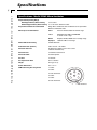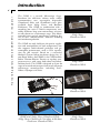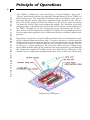
1
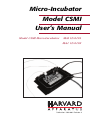
Micro-Incubator
Model CSMI
User’s Manual
Model CSMI Micro-Incubator
MAI 65-0101
MA1 65-0102
Publication 5403-002 Revision A
WEEE/RoHS Compliance Statement
EU Directives WEEE and RoHS
To Our Valued Customers:
We are committed to being a good corporate citizen. As part of that commitment,
we strive to maintain an environmentally conscious manufacturing operation. The
European Union (EU) has enacted two Directives, the first on product recycling
(Waste Electrical and Electronic Equipment, WEEE) and the second limiting the use
of certain substances (Restriction on the use of Hazardous Substances, RoHS).
Over time, these Directives will be implemented in the national laws of each EU
Member State.
Once the final national regulations have been put into place, recycling will be offered
for our products which are within the scope of the WEEE Directive. Products falling
under the scope of the WEEE Directive available for sale after August 13, 2005 will
be identified with a “wheelie bin” symbol.
Two Categories of products covered by the WEEE Directive are currently exempt
from the RoHS Directive – Category 8, medical devices (with the exception of
implanted or infected products) and Category 9, monitoring and control instruments.
Most of our products fall into either Category 8 or 9 and are currently exempt from
the RoHS Directive. We will continue to monitor the application of the RoHS
Directive to its products and will comply with any changes as they apply.
• Do Not Dispose Product with
Municipal Waste.
• Special Collection/Disposal Required.
Table of Contents
Harvard Apparatus Model CSMI Micro-Incubator
1
SUBJECT
PAGE NO.
General Information - Warranty and Repairs ........2
Specifications............................................................3
Introduction ..............................................................4
Principle Of Operation..............................................5
Supplied and Optional Accessories ....................6-7
Mounting the CSMI on a Microscope Stage ....8-10
Installation Disposable Chambers in CSMI ........11
Hookup and Operation ....................................12-15
Maintenance ......................................................16-17
Troubleshooting ......................................................18
Appendix 1: Typical Performance Curve ..............19
General Information
Harvard Apparatus Model CSMI Micro-Incubator
2
Serial Numbers
All inquires concerning our product should refer to the serial number of the unit. Serial
numbers are located on the rear of the chassis.
Calibrations
All electrical apparatus is calibrated at rated voltage and frequency. While the flow will
stay calibrated, the peak will vary.
Warranty
Harvard Apparatus warranties this instrument for a period of two years from date of
purchase. At its option, Harvard Apparatus will repair or replace the unit if it is found
to be defective as to workmanship or material.
This warranty does not extend to damage resulting from misuse, neglect or abuse, normal wear and tear, or accident.
This warranty extends only to the original customer purchaser.
IN NO EVENT SHALL HARVARD APPARATUS BE LIABLE FOR INCIDENTAL OR CONSEQUENTIAL DAMAGES. Some states do not allow exclusion or
limitation of incidental or consequential damages so the above limitation or exclusion
may not apply to you. THERE ARE NO IMPLIED WARRANTIES OF MERCHANTABILITY, OR FITNESS FOR A PARTICULAR USE, OR OF ANY
OTHER NATURE. Some states do not allow this limitation on an implied warranty,
so the above limitation may not apply to you.
If a defect arises within the two-year warranty period, promptly contact Harvard
Apparatus, Inc. 84 October Hill Road, Building 7, Holliston, Massachusetts 017461388 using our toll free number 1-800-272-2775. Goods will not be accepted for
return unless an RMA (returned materials authorization) number has been issued by
our customer service department. The customer is responsible for shipping charges.
Please allow a reasonable period of time for completion of repairs, replacement and
return. If the unit is replaced, the replacement unit is covered only for the remainder of
the original warranty period dating from the purchase of the original device.
This warranty gives you specific rights, and you may also have other rights which vary
from state to state.
Repair Facilities and Parts
Harvard Apparatus stocks replacement and repair parts. When ordering, please describe
parts as completely as possible, preferably using our part numbers. If practical, enclose
a sample or drawing. We offer a
complete reconditioning service.
CAUTION
This pump is not registered with
the FDA and is not for clinical use
on human patients.
Specifications
Harvard Apparatus Model CSMI Micro-Incubator
3
Specifications: Model CSMI Micro-Incubator
Temperature Operating Range
With Supplementary Water Cooling
5°C to 50°C
Without Supplementary Water Cooling 5° to 10° below ambient to 50°C
Disposable Chambers Accommodated
Nalge Nunc chambered slides chambered cover slips Bekton
Dikinson chambered slides
Microscopes Accommodated
Zeiss
Axiovert with attachable mechanical stage
Leica
DAS Mikroskop DMIL and DMIRB/E
w/ attach. mech. stage.
Nikon
Diaphot, TE200, TE300 series rectangle stage
Olympus
IX50/70 or IMT-s fixed stage
Peltier TED Current Rating
6 A DC Maximum
Plate Thermistor: (Built in)
100 k at 25°C - YSI 44011
Perfusion Inlet Lines
26 GA Teflon capillary up to 4 lines can be
installed simultaneously
Perfusion Rate
3 ml/minute nominal total
Perfusate Outlet
LU-ASP aspirator
Gas Port
1/16" barb
Gas Superfusion Rate
0.5 to 2.0 L/min
Weight
0.5 kg (17.9 oz)
Overall Dimensions
6.5" x 4" x 1"
CSMI Cable Plug Pin Assignment
1. Peltier
2. Peltier
3. Plate Thermistor
3
2
5. Peltier
4
6
4. Peltier
1
5
6. Plate Thermistor
Ground Shield
Introduction
Harvard Apparatus Model CSMI Micro-Incubator
4
The CSMI is a versatile Microscope StageIncubator for cell/tissue culture work, which
accommodates new rectangular disposable
Chambered slides and Chambered cover glass
available from Nalge Nunc, and Beckton
Dickinson. The CSMI in combination with a
matching low noise TC202A temperature controller facilitates long term maintenance of tissue
or cell cultures on a microscope stage. This allows
extended time optical monitoring including the
use of dyes, microinjection, electrical recording
and micromanipulation.
The CSMI not only facilitates the precise regulation and manipulation of bath temperature, but
also supports multi-channel perfusion and gas
atmosphere maintenance, such as CO2 superfusion for pH control. Based on a successful
Medical Systems Micro-incubator design for 35
mm Petrie dishes, the PDMI-2, the CSMI utilizes
Peltier Thermo-Electric Devices to regulate temperature over a wide range both above and below
ambient levels. The CSMI is designed to fit on the
stage of inverted microscopes from nearly all-major
microscope manufacturers including Zeiss,
Nikon, Olympus and Leica
Nalge Nunc
Chambered Slide
Nalge Nunc
Chambered Slide
Nalge Nunc
Chambered Slide
CSMI with Nalge Nunc Chambered Slide,
Nalge Nunc Chambered Coverglass & Beckton
Dickinson Chambered Slice
Nalge Nunc
Chambered Slide
Principle of Operations
Harvard Apparatus Model CSMI Micro-Incubator
5
The CSMI is composed of two metal plates a finned “Radiator” plate and a
“Driven” plate between which are sandwiched Thermo-Electric Devices (TED’s) or
Peltier heat pumps. The disposable chambered slide or chambered cover glass is
placed by the user within temperature regulated clamps attached to the “Driven”
plate. The TED’s pump heat from the radiator to the “Driven” plate for heating
and from the “Driven” plate to the radiator for cooling. The “direction” of the heat
pumping action is determined by the direction of DC electric current delivered to
the TED’s. Through the use of a temperature sensor mounted on the “Driven “
plate and an external temperature controller (TC202A) that uses feedback control,
precise temperature regulation can be achieved both above and below ambient temperature.
If perfusion is required, two 26 GA Teflon perfusion lines can be mounted in each
of the L shaped temperature driven claps. A separate aspirator is used to maintain
fluid level irrespective of perfusate flow rate. Gas for superfusion over the chamber
is delivered to a white 1/16th in barb port also attached to each L clamp. The exit
for the gas is a narrow opening on the inner long surface of each L clamp facing
the installed chamber. Having the perfusion lines and superfusion gas fed through
the temperature regulated L clamps assures that fluid and gas delivered to the
chamber are pre-temperature regulated before they arrive in the tissue culture dish.
Diagram of CSMI parts
Supplied and Optional Accessories
Harvard Apparatus Model CSMI Micro-Incubator
6
The CSMI chamber depicted above is a flexible system that can be used in several
modes of operation. These include perfused and static modes, with or without gas
superfusion, with a bath thermistor or without and of course mounted on different microscope stages. The CSMI is shipped with the most commonly used accessories, which are packed separately and identified below.
Supplied Accessories
Catalog No.
Description
65-0047
Leiden Aspirator on magnetic base
LU-ASP for media removal
during perfusion
65-0055
Bath Thermistor holder
on magnetic base
7501-121
A set of two 4’ lengths of 1/8"
ID Tygon tubing for
gas superfusion
7501-122
A set of two 4’ lengths of 1/8"
ID Tygon tubing with compler
for 26 GA Teflon perfusion
tubing for perfusion
7501-123
A 4’ length of 1/16" Tygon tubing
for use with the Leiden Aspirator
Supplied and Optional Accessories
Harvard Apparatus Model CSMI Micro-Incubator
7
7501-124
One spare set of two
26 GA Teflon perfusion
lines molded into proper
shape for easy insertion in
temperature driven clamps
7501-125
Two set of spare
Thermo-conductive self
adhesive elastomer pads to
line the inner contacting
surface of the L shaped clamps.
7501-126
Clear plastic cover with
magnetic hold down frame.
7501-127
A set of 4 nylon set-screws
for use when mounting on
Nikon or Olympus inverted
microscopes.
Optional Accessories
65-0103
A copper water tube shaped to fit the
slots in the CSMI radiator fins is
available for applications where bath
termperatures apporaching 0˚ C are
required. In this case running tap water
in the installed copper tube is used to
improve the efficiency of heat removal
from the CSMI in order to achieve this lower temperature range.
7501-127
Replacement tubing and Pad Kit
containing all tubing and thermo
Mounting the CSMI on a Microscope Stage
Harvard Apparatus Model CSMI Micro-Incubator
8
The CSMI is equipped for easy mounting on microscope stages of several of the
most popular inverted microscopes. There are two major considerations when
installing the CSMI first is mechanical attachment to the stage and second is heat
transfer between the CSMI and the microscope stage. Mechanical fixation is desirable because X-Y translation of the specimen can then be done using the microscope built in stage movement mechanism. In addition when the CSMI is mounted on a microscope stage, the stage which is generally made of material like aluminum serves as a low Thermo resistance pathway to conduct heat to or away from
the CSMI. . In general when the CSMI is placed on a flat microscope stage, it is
the Radiator portion that comes in contact with the stage. The “Driven” (temperature regulated) plate that holds the specimen is recessed slightly and does not
come in contact with a flat stage. Specimen cooling performance of the CSMI is
improved by extra heat removal through the microscope stage. Specimen heating
performance is less affected by mounting considerations
The following table describes how to mount the CSMI on various brands of
Inverted Microscope.
Brand
Description
Zeiss
The CSMI is designed to fit directly into the
holding clips of the Attachable Mechanical Stage
available with Ziess inverted microscopes with the
"M type" Mechanical Stage. For "K type"(3 Plates Stage),
CSMI will need to be modified. Call Harvard Apparatus.
Leica
Inverted microscopes. The CSMI is designed to fit directly
into the holding clips of the Attachable Mechanical Stage
available with Leica inverted microscopes
Mounting the CSMI on a Microscope Stage
Harvard Apparatus Model CSMI Micro-Incubator
9
Note: The micro-incubator CSMI Cat# 65-0102 has the same construction as the
regular CSMI Cat# 65-0101, with the difference that the bottom plate of the
65-0102, has been designed to be used in the following microscopes:
ZEISS and LEITZ with 3-Plate mechanical Stage (known as “K” type) LUDL and
PRIOR motorized stage in inverted microscopes.
The 65-0102 will fit on the microscope stage with the dimensions of
160mm x 110mm.
Both CSMI Cat# 65-0101 and the 65-0102 can be used on microscope stages with
“FLAT” surface and with a round opening between: 88 mm to 110 mm.
To avoid vibration (if any), modeling clay or dentist wax could be applied at the
edge of the micro-incubator.
Microscope stage “M”
Type 65-0101
Mounting frame M for specimen
slider 76 x 26 mm
Object guide
130 x 85 mm right
Object guide
130 x 85 mm left
Microscope stage “K”
Type 65-0102
Specimen stage
250 x 230 mm
Mounting frame K for specimen slider
Mounting frame K for reflected light, d=72 mm
Stage stop d=28 mm
Stage stop d=35 mm
Stage stop d=18 mm
(further stage stops being prepared)
Mechanical stage
130 x 85 R/L without
mounting frames
Gliding stage Z
with stage inserts
d=24 mm and 48 mm
Mounting the CSMI on a Microscope Stage
Harvard Apparatus Model CSMI Micro-Incubator
10
Nikon
Nikon inverted microscopes have a
stage opening that is 108 mm in
diameter. The CSMI is mounted
over this opening using four nylon
set screws inserted into four tapped
holes located on an 108 mm
diameter in the bottom of the CSMI.
The setscrews protrude into the edges of this opening, locking
the CSMI to the stage for X-Y translation.
Olympus
Olympus inverted microscopes have
a stage opening that is 80 mm in
diameter. The CSMI is mounted over
this opening using four nylon set
screws inserted into four tapped
holes located on an 80 mm diameter
in the bottom of the CSMI. The
setscrews protrude into the edges of this opening, locking the
CSMI to the stage for X-Y translation.
Other
For microscopes not mentioned above,
contact Harvard Apparatus Inc. technical
support to discuss mounting options.
Please Note Though CSMI can be rested
and operated on a microscope stage surface.
Care must be taken that only the finned
“Radiator “ plate comes in contact with the stage.
The temperature controlled “Driven “ plate must
not touch any part of the microscope.
Installation of Disposable Chambers in CSMI
Harvard Apparatus Model CSMI Micro-Incubator
11
The CSMI is a finned rectangular assembly with two temperature controlled L
shaped clamps inside. To install a disposable chambered slide or chambered cover
slip refer to the drawing below:
First open the two L shaped clamps fully by sliding them diagonally away from the
center. Push on the knurled knobs at the corner of each clamp. Caution do not try
to force the clamps in the X or Y direction they only slide diagonally.
Once the Clamps are open, carefully insert the Chambered slide or chambered
cover slip so that it rests on the metal strips in the opening. Note: care must be
taken, that disposable chambers do not fall through the opening in the floor of the
CSMI during installation, spilling their contents. This may be a problem on installation more so with Chambered cover slips which are shorter than Chambered
slides.
Once the disposable chamber rests on the floor of the CSMI, slide the L shaped
clamps inward diagonally to the closed position with care so that the contents are
not spilled.
Make sure the clamps are firmly pressed against the sidewalls of the disposable
chambered slide or cover slip. This is to insure good thermal contact between the
clamps and the chamber wall for proper heat transfer and temperature control. The
inner, chamber contacting surfaces of the clamps are equipped with a Thermo-conductive elastic lining. This lining is designed to mold itself around imperfections
and high spots in the injection molded chamber walls, to prevent air gaps that
might reduce heat transfer and performance.
Hookup and Operation
Harvard Apparatus Model CSMI Micro-Incubator
12
1. Connection to Temperature Controller (Please also refer to the
TC202A Users manual for additional operating instruction)
To prepare for operation the CSMI is connected to a TC202A temperature controller by plugging its cable end plug into the I/O socket on the TC202A front
panel. The TC202A can sense CSMI “Driven” plate temperature through this
cable, as well as supply power to the Peltier heat pumps. The TC202A also supports
an optional second temperature sensor, the “Bath Thermistor” which can be inserted in the disposable chamber media to measure temperature therein. The “Bath “
Thermistor is not always used, if it is it has its own cable and plug and should be
connected to the TC202A at this time.
Drawing or photo of CSMI connection to TC202
2. Using the Plate or Bath Thermistor for temperature feedback and control
During operation there generally is a difference in temperature between the temperature “Driven Plate” and the media in the disposable chambered slide (Bath).
The gradient between Plate and the center of the Bath could be 1 to 4 (C depending on such factors as thermal resistance of the chamber wall, media depth, perfused or static operation, gas superfusion etc. The offset is positive or negative
depending on whether one is heating or cooling.
Though we always want to control temperature in the bath, often Plate control is
the best solution. This is the case for example in situation where media sterility is
required and the burden of sterilizing the bath thermistor makes it impractical. The
Plate temperature can be offset manually to stabilize at a higher or lower temperature in order to compensate for any difference between bath and plate.
Hookup and Operation
Harvard Apparatus Model CSMI Micro-Incubator
13
For the most part the safest mode of operation is to use the Plate thermistor as the
control point. Plate control has the advantage of not being subject to unintended
“open loop “ operation, where temperature control is lost. This can occur accidentally with bath control, but is highly unlikely with plate control. A bath thermistor can become accidentally dislodged from the bath so that it no longer measures bath temperature. During extended operation media evaporation can uncover
the bath thermistor-sensing tip, causing it to read incorrectly. In this case the temperature controller loses control. With plate control bath temperature can still be
precisely monitored by a Bath thermistor but control will not be dependent on it.
Plate control also has the advantage of bringing the system to the control point
temperature faster than Bath control. The bath temperature lags the plate temperature. This lag causes the system to take longer for bath temperature to settle at the
control set point.
With the above caveats in mind, bath control has a major advantage over plate control. With the bath thermistor as the control point, the temperature controller
automatically compensates for the temperature gradient between plate and bath
and for changing environmental conditions including perfusion changes.
Probably the best strategy is to quickly bring the bath to the target temperature
using plate control. Then switch to bath control for the greatest precision in long
term temperature maintenance.
3. Installation of optional
Bath Thermistor
The “Bath Thermistor” is inserted in
the media and held in place using the
supplied magnetic base thermistor
holder which attaches to the ferrous
(chrome plated) top surface of each L
shaped clamp. If the plastic cover
with magnetic frame is to be used
over the chamber in conjunction
with the Bath thermistor it can either
be slid open partially to accommodate the thermistor. Alternatively a 1/8" hole can
be drilled in the cover where the bath thermistor is to pass through.
4. Static operation
For static or non-perfused operation, a chamber with media is installed and a set
point is entered into the temperature controller. If 37 ( C is selected, it will take
approximately 25 minutes for the temperature to stabilize starting from room temperature. At this higher temperature long term incubation will result in media loss
through evaporation. Using mineral oil over aquious media can slow this. If mineral oil cannot be used, the clear plastic cover, which is supplied, can also reduce
evaporation.
Hookup and Operation
14
Harvard Apparatus Model CSMI Micro-Incubator
5. Perfused Operation
Perfusion is a useful tool to study pharmaceutical effects both in applied and
washout modes. To establish perfusion, perfusate is delivered to the chamber
through 26GA. Teflon capillary tubing. Two such perfusion lines are installed in
close fitting slots in the temperature controlled L clamps that surround the chamber. The perfusate supply, which can be kept at room temperature, is warmed or
cooled by conduction before delivery into the chamber bath. The perfusate should
be delivered at a rate of 1 to 3 ml/min. This is best accomplished by a peristaltic
pump, like the Harvard Apparatus model ‘66’ catalog # 55-7766. A set of two 1/8"
Tygon hoses with couplers for the 26 GA. Teflon capillaries are supplied, to make
the connection to the peristaltic pump or other perfusion source.
If perfusion is to be continuous than bath media must be removed to prevent overflow. A unique adjustable aspirator the LU-ASP catalog # 65-0047, is supplied
which can automatically maintain a constant fluid level with minimal fluctuations
in that level as it works (see adjacent drawing). Fluid level fluctuations not only can
disturb optical measurements, but can also be a source of electrical noise, if sensitive Electro-physiologic recording such as patch clamping is done. . The aspirator
has a magnetic base to grip the magnetic surface on each of the L clamps. The level
of fluid in the chamber is determined by the height of the aspirator in the bath, and
can be adjusted with its thumbscrew. A source of suction with a liquid trap is connected via the supplied 1/16 “ Tygon tubing. Because of the design of the aspirator the user can operate one or more perfusion lines simultaneously without further adjustment to the aspirator.
During perfused operation
media is replenished continuously and evaporation is not a
problem until perfusion is
halted. If perfusion is to be
interrupted the plastic cover
should be used to minimize
evaporation. The plastic cover
is supplied without any holes
drilled. If it is to be used
simultaneously with a LUASP aspirator, as is the case
with a bath thermistor, the
user can partially slide the cover back, or alternatively drill a hole to accommodate
the aspirator. . The drawing below depicts the hookup for perfusion.
Operating the temperature controller for perfusion is similar to operation in
static mode. Because of feedback control the temperature controller will automatically adjust power delivered to the heat pumps to compensate for the additional
load imposed by perfusion, irrespective of whether plate or bath control is used.
Hookup and Operation
15
Harvard Apparatus Model CSMI Micro-Incubator
6. Gas superfusion
Gas superfusion is often used to aid
in pH balance (5% C02 ) as well as
for improved oxygenation. The
CSMI has provisions for delivering
gas via a cavity in the temperature
regulated L clamps to a slit just over
the edge of the disposable chambered slide. This causes the gasses to
be delivered to the chamber pre temperature regulated. Heavier than air
gasses like C02 will then fall into the
chamber cavity. With the aid of the supplied plastic cover a low-pressure atmosphere of any desired gas mixture can be maintained in the chamber. The gas is
delivered from a tank equipped with a regulator and flowmeter, to the white barb
fitting at the long end of the temperature regulated L clamp. A 1/8 “ Tygon hose
is supplied for this purpose. Both L clamps have gas ports. These can be used simultaneously or separately for the same or different gasses. The drawing below depicts
the hookup for gas superfusion.
Operating the temperature controller with gas superfusion is similar to operation
in static or perfused mode. Because of feedback control the temperature controller
will automatically adjust power delivered to the heat pumps to compensate for the
additional load imposed by gas superfusion, irrespective of whether plate or bath
control is used. Gas superfusion can be done in conjunction with fluid perfusion
as well as with static protocols.
7. Special considerations for cooling
At room temperature the CSMI is
more efficient in heating than cooling the disposable chambered slide.
Although the CSMI can easily attain
and hold any temperature between
ambient and 50° C, it is limited to
cooling to a range of 5 to 10° C
below ambient depending on
mounting particulars. This is due to
the limited efficiency in heat
removal afforded by the air radiating
fins combined with the microscope stage. For users who want to cool to lower temperatures than this, an optional auxiliary copper water radiator tube is available that
fits in a slot cut into the radiating fins. Running tap water in this auxiliary radiator improves cooling performance greatly so that single digit temperatures can be
maintained. The Drawing below depicts the auxiliary radiator in place.
Maintenance
Harvard Apparatus Model CSMI Micro-Incubator
16
Perfusion tubing replacement:
The installed Teflon capillary perfusion tubing can be used many times if kept
clean. The perfusion lines should be flushed with distilled water after use to avoid
cross contamination. Occasional perfusion of 70% alcohol will help avoid growth
of microorganisms.
Should replacement of perfusion tubing be
required, a spare set of two lines is included
with each CSMI. The perfusion tubing is preformed to the circuitous shape of the grooves
into which it is to be installed, to makes it easier to install the rather stiff Teflon capillary. To
obtain additional sets order.
A set of Perfusion tubing
shaped to fit into L clamps
To replace the perfusion lines follow the
steps 1-6, referring to the drawing of the temperature driven L clamp below.
1.
Remove holding the chrome plated L clamp cover.
2.
Remove the Chrome plated cover, and the black tubing cover resting
inside to reveal the perfusion lines.
3.
Note the way the perfusion lines are installed in their heat transfer slots.
The two lines are not the same but are shaped differently to fit in different
positions in the L clamp.
4.
Lift and discard the installed tubing and replace with a new set.
5.
Make certain that the tubing rests fully in the heat transfer groves,
and install the black tubing cover.
6.
Replace the Chrome cover and re-fasten with the two Phillips screws and
1 knurled knob removed earlier.
Perfusion tubing installation drawing
Perfusion tubing installation drawing
Maintenance
Harvard Apparatus Model CSMI Micro-Incubator
17
Replacement of elastic Thermo-conductive L clamp lining:
Each L clamp is lined with flexible Thermo-conductive material, on all inner walls
that come in contact with the disposable chamber. The lining is designed to conform to irregularities in the surface of the disposable chamber, as the L clamps
close. Tight air-pocket free contact between the L clamps and the chamber is
required to guarantee maximum heat transfer between the temperature driven L
clamps and the disposable chamber.
The lining can be used for many open and close cycles. Should it become damaged
it can easily be replace by the user. A spare set of self-adhesive lining pads is packed
with each system. To reorder use (Cat. # 7501-125)
To replace:
1.
Open the L Clamps to their full open position, and remove any
chamber within.
2.
Peel the existing lining pads off from the inner chamber wall.
3.
Clean the surface that held the pads with alcohol (use Q-tip or equiv.)
and let dry.
4.
Remove the backing from the adhesive surface of a new lining pad and
attach to the long surface of an L clamp. Position carefully so that the
Gas inlet slit near the top of the L clamp is not blocked.
5.
Repeat the procedure with a “short” lining pad.
Troubleshooting
Harvard Apparatus Model CSMI Micro-Incubator
18
The following table lists some problems, possible causes and remedies. This is not
meant to be exhaustive, but as a checklist to allow the user to solve the more common occurrences. Many problems arise from improper use of the TC202A temperature controller. Please refer to the TC202A user’s manual if the problem you
experience is not listed here.
Problem
Description
1. The bath temperature does not reach
a heating set point.
1a. The L Clamps are not closed tightly
around the chamber. -Check and fix.
1b. Static fluid level is too low-raise
1c. Perfusion rate is too high-lower
below 3 ml/min
2. The bath temperature does not reach
a cooling set point.
2a. The L Clamps are not closed tightly
around the chamber. -Check and fix
2b. Static fluid level is too low-raise
2c. Perfusion rate is too high-lower
below 3 ml/min
2d. Set-point is outside of working range
without auxiliary water radiator- change
setting or add auxiliary water radiator
3. Bath temperature is rising above
ambient even though set-point is for
cooling below ambient
3a. Set-point is outside of temperature
working range without auxiliary water
radiator- change setting or add
auxiliary water radiator
4. Excessive 50/60 Hz. noise in
4a. CSMI ground not connected (through
Electro-physiologic recording done from
TC202A mains protective ground pin
tissue in the chamber.
in power cord) or connected to
poor ground. - Plug TC202A into better
grounded power outlet or into same
outlet as recording equipment
4b. Remove bath thermistor if used, and use
only plate thermistor and plate control
5. Bath temperature inaccurate or
unchanging
5a. Replace bath thermistor
Appendix 1: Typical Performance Curve
Harvard Apparatus Model CSMI Micro-Incubator
19
The above performance curve was obtained using a Nunc chambered coverglass
chamber. The bath chamber contained 2.5 ml of water under static conditions with
a plastic cover slid back to accommodate the bath thermistor. The dark blue curve
represents the set point entered into the TC202A temperature controller. The light
blue curve is the temperature measured at the radiator fins.