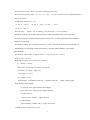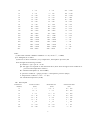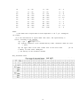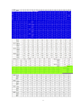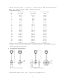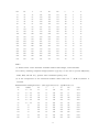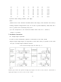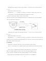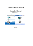
1
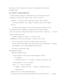
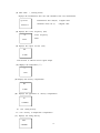
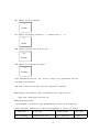
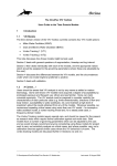
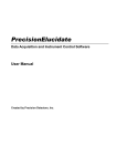
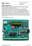
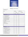
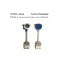
DH800 serise
Vortex Flowmeter
Reliable flow measurement of gas, steam and liquids
1
Operating Instruction
CONTENTS
1
Summary
1
2
The working principle
1
Main characteristics
4
3
3.1
Simple structure
3.2
Series, DN25-DN600
3.3
Two-wire output current pulse, three-wire
3.4
Intelligent
3.5
Built-in …….
4 Technical parameters
4.1
Normal diameter DN
4.2
Connection type
4.3
Normal pressure
4.4
Medium temperature
4.5
Accuracy
4.6
Meter material
4.7
Medium
4.8
Medium viscosity
4.9
Velocity scope of flow
4.10
Output signal
4.11
Working Power Supply
4.12
Resistance coefficient
4.13
Atmospheric pressure
4.14
Ambient temperature
4.15
Explosion-proof class
4
2
4.16
5
Protection grade:IP65,IP68
Measuring range
5.1、Gas
5.2
(Model Selection Parameters)
6
(Air)
Fluid liquid
5.3、Saturated steam
5.4 Superheated steam
6
External dimensions
6.1 Dimensions of
11
Wafer type (mm)
6.2 Dimensions of Flanged type (mm)
7. Installation Instruction
13
7.1 Straight length requirement
7.2
Vortex diameter
7.3 use
our special gaskets
7.4 Horizontal, vertical and slanting installation.
7.5 Try to avoid strong shock pipeline
7.6 Try to avoid high-temp thermal source
7.7 Grounding requirement.
7.8 Try to avoid shock places and corrosion environment
7.9 If it needs to…….
8. Connection of Meters
15
8.1 Three-wire system circuit connection
8.2 Two-wire system circuit connection
9. Attentions
16
9.1Measurement of Medium
9.2 Try to avoid…….
9.3 If a valve is installed near……
9.4 The meter has been
10.Parameter setting/configuration
17
10.1 Status display
3
10.2 Operating Procedures
10.3
Flameproof
INTRODUCTION
1. Summary
Darhor Technology
Co., Ltd used international advanced testing technologies to
developed piezoelectric intelligent DH900 type
vortex flowmeter, the products have made a
breakthrough progress in the antivibration, reliability, high temperature, etc. They comply with JB/T9249-1999 "Vortex Flow
Sensor" industry standard and can be used in measure saturated steam, superheated steam, high
and low temperature liquids, gases and other media, They widely used in metallurgical
chemical, light industry, food and sewage treatment industries.
2. The working principle
Vortex flowmeter is based on "Karman vortex street" principle of the development of a
fluid oscillation type flowmeters, use of modern electronic detection technology to detect the
vortex frequency, through the treatment of convertor ,it sends 4-20mA current signal , By using
our company ‘s temperature transmitter and display monitor ,It can show high quality test
results.
Computational formula as follows:
F=St*V/md ……………………………….........………….……… Formula 1
Q=3600*F/K …………………………….........………….…
……Formula 2
M=Q*ρ ……………………………….........…………….………… Formula 3
4
Among Formula:
F……Fluid flow through bluff body generate frequency of vortex ( Unit : Hz)
St…Strouhal constant ( zero dimension )
V……Mean velocity of fluid inside the pipeline ( Unit : m/s)
m……The ratio between Lune Circulation area of bluff body at both sides and cross-sectional area
(Unit: zero dimension)
d……Upstream face width of bluff body inside vortex flowmeter ( Unit : m )
D……Inside diameter (ID) of vortex flowmeter ( Unit : m )
Q……Instantaneous volume flow ( Unit : m3 / h )
K……Instrument coefficient of vortex flowmeter ( Unit : pulses / m3 )
M……Instantaneous mass flow ( Unit : kg/ h )
ρ...…Fluid density ( Unit : kg/ m3 )
Note: vortex flowmeter "K" coefficient is corresponding with one diameter, the exact ''K" value should be
calibrated in practice. Viz. one cubic meter fluid through sensor output numbers of pulse under working
condition.
3. Main characteristics
3.1 Simple structure , high reliability and trouble-free long-term use;
3.2 Series, DN25-DN600-mounted structure using Wafer version or Flange version,
can be selected to adapt to different users;
3.3 Two-wire output current pulse, three-wire voltage pulse
4-20mA analog voltage signal, to
adapt to a variety of end-user
3.4 Intelligent, wide variety of medium-caliber amplifier common, including non-traffic signal
automatic recognition software has greatly enhanced anti-jamming performance
instrumentation;
3.5 Built-in LI- battery(3.6VDC ) can be displayed at the screen, can be 24VDC for the screen
outside the show that, can be displayed outside the screen at the same time for the 24VDC
output 4-20mA analog current
signal;
4.Technical parameters
4.1 Normal diameter DN (mm):
15,20,25,40,50,80,100,125,150,200,250,300 ,350,400,450,500,600
5
4.2 Connection type : Wafer connection or Flanged connection ,
4.3 Normal pressure (Mpa): 1.6,2.5,4.0
level ,the other pressure class recommend priority or
supply agreement
4.4 Medium temperature (℃)
(1) -40 ℃ ~ 150 ℃;
(2) -40 ℃ ~ 250 ℃ (3)-40 ℃ ~ 350 ℃
(4)-40 ℃ ~ 425 ℃
4.5 Accuracy:
liquid ± 1% of reading , gas and steam ± 1.5% of reading
4.6 Meter material : the casing of the transmitter is made in aluminum alloy ,the material of
contacting medium: SUS304,SUS316,SUS316L,HC-276, or other special materials according to
customers’ requirement.
4.7 Medium: liquid , gas ( including natural gas ), steam ( saturated steam and superheated steam.etc
4.8 Medium viscosity:Range of Reynolds numbers: normally 20000-7000000 , extensionally
8000-7000000.
4.9 Velocity scope of flow : Liquid (0.30 m/s…7 m/s), gas (3.0 m/s…60 m/s)
,steam (3.0 m/s…70 m/s)
4.10 Output signal: (Two versions are available:)
(1)
Remote
version
three-wire voltage pulse (supplier agreement)
lower PWL<1V, higher PWL>6V)
lower [0] 1V [1] 5V
(2)compact version
status display
instantaneous flow rate,cumulative flow rate ,output 4-20mA signal
4.11 Working Power Supply:
(1) voltage pulse output without status display
Type :three-wire voltage pulse output: AC220V
(2) status display
Type:two-wire 4-20mA
output: DC 24V
(3) status display
Type:Li Battery-3.6VDC /5Ah (> 2 years service life)
4.12 Resistance coefficient: Ca<2.4
6
4.13 Amospheric pressure: 86kPa-106kPa
4.14 Ambient temperature: -40 ℃ ~ +55 ℃ ,humidity:<90% RH
4.15 Explosion-proof class: Intrinsic safety ExiaⅡCT1-4;
Flame-proof ExdⅡCT1-4
4.16 Protection grade:IP65,IP68
(IP68 supply by negotiation)
5. Measuring range (Model Selection Parameters)
Model Selection (LUGB Pipeline-version Vortex Flowmeter)
DH900
.A
B
C
D
E
F
G
A. Pipelined Vortex Flowmeter Connection amplifier and sensor:
1. flange Connection
(P/T compensation required)
2. wafer Connection (Priority)
B. Measurable medium:
1. Gas, Liquid, Steam
2. Liquid
3. Gas
4. Saturated steam & superheated steam
C. Diameter of Vortex Flowmeter
DN(mm):15,20,25,32,40,50,65,80,100,125,200,250,300,350,400,450,500,600
D: Explosion-proof class
null. without explosion-proof certificate and its protection level - IP65 (IP67, IP68)
B. intrinsic safety ExiaⅡCT4; ExibⅡCT4
2. flame-proof ExdⅡCT6
E. Signal output
Null:
voltage pulse ( 12/24VDC )
C:
4-20mA , LCDstatus display (24VDC )
D:
without signal output and status display (3.6V Li Battery)
F. Measurable pressure class
Null: 1.6MPa
2:
2.5Mpa
4:
4.0Mpa
7
H
G: Meter body material
Null : SUS304
M
: SUS316
L
: SUS316L
H: Flange material
Null : carbon steel
S
:SUS304
Order Notice:
Diameter:
DN
Name of liquid:
--------
mm
-------
Chemical characteristics:
-------
Velocity scope of flow:
Max---------
Medium temperature:
-------℃
,Min---------
Medium pressure:
-------- MPa
Medium density:
---------kg/dm3
Meter Output signal:
---------------
Explosion-proof class:
---------------
Protection grade:
---------------
5.1、Gas
Nominal Size
DN(mm)
15
t/m3
(Air)
Normal work flow
Measurable flow
Nominal Pulse Rate
(m3/h)
(m3/h)
(Hz)
5 ~ 30
5 ~ 40
8
460 ~ 3700
20
6 ~ 50
6 ~ 60
220 ~ 3400
25
8 ~ 60
8 ~ 120
180 ~ 2700
32
14 ~ 100
14 ~ 150
130 ~ 1400
40
18 ~ 180
18 ~ 310
90 ~ 1550
50
30 ~ 300
30 ~ 480
80 ~ 1280
65
50 ~ 500
50 ~ 800
60 ~ 900
80
70 ~ 700
70 ~ 1230
40 ~ 700
100
100 ~ 1000
100 ~ 1920
30 ~ 570
125
150 ~ 1500
140 ~ 3000
23 ~ 490
150
250 ~ 2500
200 ~ 4000
18 ~ 360
200
400 ~ 4000
320 ~ 8000
13 ~ 325
250
600 ~ 6000
550 ~ 11000
11 ~ 220
300
1000 ~ 10000
800 ~ 18000
9 ~ 210
350
1500 ~ 15000
1100 ~ 24000
8 ~ 175
400
1800 ~ 18000
1500 ~ 30800
7 ~ 143
450
2100 ~ 21000
2000 ~ 35000
6 ~ 90
500
2500 ~ 25000
2000 ~ 48000
5 ~ 120
3200 ~32000
2500 ~70000
600
3.5 ~98
Notes:
(1)This table assumes standard conditions of: Air, t0=20 ℃ , 0.1MPa,
ρ0=1.205kg/m3,v0=3~60m/s
(2)The air in other conditions (very temperature, atmospheric pressure) the
flow through the following formula:
Q condition = Q0 * p0 / P * T/T0
Q0: the upper corresponds to the minimum flow (flow from the upper limit condition of
pressure and temperature effects)
P0: standard atmosphere (0.101325MPa)
P: pressure condition = gauge pressure + atmospheric pressure (Mpa)
T: temperature condition = 273 + t ℃ (K)
T0: standard temperature (273K)
5.2
Fluid liquid
Nominal Size
Normal work flow
Measurable flow
Nominal Pulse Rate
DN(mm)
(m3/h)
(m3/h)
(Hz)
15
1 ~ 6
0.8 ~ 8
90 ~ 900
20
1.2 ~ 8
1 ~ 15
40 ~ 600
25
2 ~ 16
1.6 ~ 18
35 ~ 400
32
2.2 ~ 20
1.8 ~ 30
20 ~ 250
40
2.5 ~ 25
2 ~ 48
10 ~ 240
50
3.5 ~ 35
3 ~ 70
8 ~ 190
65
6 ~ 60
5 ~ 85
7 ~ 150
80
13 ~ 130
10 ~ 170
6 ~ 110
100
20 ~ 200
15 ~ 270
5 ~ 90
9
125
30 ~ 300
25 ~ 450
4.5 ~ 76
150
50 ~ 500
40 ~ 630
3.8 ~ 60
200
100 ~ 1000
80 ~ 1200
3.2 ~ 48
250
150 ~ 1500
120 ~ 1800
2.5 ~ 37.5
300
200 ~ 2000
180 ~ 2500
2.2 ~ 30.6
350
300 ~ 3000
220 ~ 3500
1.7 ~ 27
400
350 ~ 3500
300 ~ 4500
1.4 ~ 21
450
420 ~ 4200
400 ~ 6000
1.2 ~ 15
500
500 ~ 5000
400 ~ 7100
1.0 ~ 17.8
600
700 ~ 7000
500 ~ 10000
0.7 ~ 14
Note:
(1) The table refers to liquid water at room temperature t = 20 ℃, ρ0 = 1000kg/m3,
v0=1~10m/s
(2) if the measurement of liquid rather than water, and liquid density is
known, according to the formula:
Qρ = Q0 ×
(ρ0 / ρ)
Qρ: working conditions in the medium-density traffic conditions under the lowe
r limit;
Q0: the upper table in the same caliber flow of the lower limit
ρ0: th
e density of water taken 1000kg/m3
ρ: the density of the measured medium
5.3、 Saturated steam
10
11
Note :AP:Absolute pressure (MPa) T:Temperature (℃ ) D:Density (kg/m3),Maxm:Max measurable flow(kg/h)
Maxn: Max normal work flow(kg/h)
Minn: Min normal work flow(kg/h)
5.4 Superheated steam
DN
Max measurable
Max normal work
Min normal orkflow
(mm)
Flow (kg/h)
Flow (kg/h)
(kg/h)
15
38.2× ρ
49.5× ρ
8.24× ρ
20
67.8× ρ
79× ρ
9.88× ρ
25
106× ρ
104× ρ
13.12× ρ
32
174× ρ
184× ρ
23× ρ
40
271× ρ
265× ρ
26.65× ρ
50
424× ρ
494× ρ
49.41× ρ
65
716× ρ
823× ρ
82.35× ρ
80
1085× ρ
1153× ρ
115.3× ρ
100
1696× ρ
1647× ρ
164.7× ρ
125
2649× ρ
2471× ρ
247.1× ρ
150
3815× ρ
3294× ρ
329.4× ρ
200
6782× ρ
6588× ρ
658.8× ρ
250
10596× ρ
9882× ρ
988.2× ρ
300
15260× ρ
16470× ρ
1647× ρ
350
20771× ρ
24710× ρ
2471× ρ
400
27130× ρ
29650× ρ
2965× ρ
450
34336× ρ
34590× ρ
3459× ρ
500
42390× ρ
41180× ρ
4118× ρ
600
61042× ρ
52700× ρ
5270× ρ
Note: ρ : the density of superheated steam
in working conditions , ( reference thermo-technical
handbook by temperature and pressure )
6.
EXTERNAL DIMENSIONS
A
Wafer version (type A)
6.1 Dimensions of Wafer version
B
(mm)
Flanged version (type B)
(type A:DN,D1,L,H. type B:D1,D0,C,n,d)
12
DN
D1
L
H
D1
D0
C
n
d
15
85
78
345
148
118
20
4
18
20
85
65
350
148
118
20
4
18
25
85
65
350
148
118
20
4
18
32
85
65
350
148
118
20
4
18
40
85
65
350
148
118
20
4
18
50
95
80
355
155
125
20
4
18
65
105
80
362
172
142
20
4
18
80
120
80
370
180
150
20
4
18
100
140
100
380
200
170
25
4
18
125
160
110
390
224
194
25
6
18
150
185
150
405
265
225
27
6
22
200
245
165
432
313
277
30
8
22
250
295
200
460
375
331
32
10
26
300
345
200
484
425
381
35
10
26
350
395
230
510
475
431
35
16
26
400
445
230
534
525
481
35
16
26
450
500
280
560
580
536
45
16
30
500
550
320
584
635
591
45
16
30
600
650
360
634
745
701
60
20
30
Note :
(1) Wafer-version vortex flowmeter assemble made-to-order flanges, when flowmeter
leave factory including companion flanges(reference (type B)). we are able to provide GB(China);
ANSI; DIN; JIS and etc.), pressure class recommend priority level.
(2) If the temperature of the measured medium rather than 150 ℃ ,H=H+75,radiator is
installed.
6.2 Dimensions of Flanged version
(mm) (type A:DN,D1,L,H. type B:D1,D0,C,n,d)
DN
P(MPa)
D1
C
L
H
D0
n*φd
15
1.6 ~ 4.0
95
14
180
345
65
4*14
20
1.6 ~ 4.0
105
16
180
350
75
4*14
25
1.6 ~ 4.0
115
16
180
350
85
4*14
32
1.6 ~ 4.0
140
18
180
350
100
4*18
40
1.6 ~ 4.0
150
18
180
350
110
4*18
50
1.6 ~ 4.0
165
20
200
355
125
4*18
65
1.6
185
22
200
362
145
4*18
80
1.6
200
24
200
370
160
8*18
100
1.6
235
26
250
380
190
8*18
125
1.6
270
28
250
390
220
8*18
150
1.6
300
30
300
405
250
8*22
200
1.6
375
36
350
432
320
12*22
13
250
1.6
450
42
400
460
385
12*26
300
1.6
515
48
500
484
450
12*26
350
1.6
580
55
550
510
510
16*26
400
1.6
660
60
600
534
585
16*30
450
1.6
685
66
600
560
610
20*30
500
1.6
755
72
600
584
670
20*33
600
1.6
890
84
600
634
795
20*36
P:pressure under working condition ( unit: Mpa)
Note :
(1)Wafer-version vortex flowmeter assemble made-to-order flanges, when flowmeter leave factory i
ncluding companion flanges(reference (B)). we are able to provide GB(China); ANSI; DIN; JIS a
nd etc.), pressure class recommend priority level.
(2) If the temperature of the measured medium rather than 150 ℃ ,H=H+75,
radiator is installed.
7. Installation Instruction
7.1
Straight length requirement
In order to correct measurement, upstream or downstream of flow meter should
obligate enough straight length. No components to effect fluid velocity in upstream of flow meter.
All types of straight length installation reference:
Vortex Flowmeter Straight Length Size Drafts (Fig 7.1)
Fig 7.1
Reducer pipe: Ensure the upstream straight pipe length to be 15D or more, and the
raight pipe length to be 5D or more for per reducer
14
downstream st
Expander pipe: Ensure the upstream straight pipe length to be 25D or more, and the downstream st
raight pipe length to be 5D or more for per expander pipe.
Valve position and straight pipe length: In case the valve has to be installed on the upstream of th
e
flowmeter, ensure the upstream straight pipe length to be 50D
or more,
and the downstream
straight pipe length be 5D or more
7.2
Vortex diameter is accordant to upstream and downstream tubing diameter at installation point;
sensor is concentric
with pipeline; prohibit gaskets between sensor and flanges bulge out into pip
eline. Make sure that the connection end face of
insertion-version(Wafer type) vortex flowmeter parallel to the pipe axis.
7.3 use
our special
gaskets
for Vortex diameter,
Details as No.1-No.2
Fit a gaskets inside the groove of the flang
e.
7.4 Horizontal, vertical and slanting installation. Liquid measuring ensure flow direction from low to
high. Gas measuring, direction no required.
7.5 Try to avoid strong shock pipeline, or take some measures of shock absorption. It should be av
oided to install the Vortex diameter to long overhead pipes, as the drooping of the transmitter can
easily cause the seal leakage between flange and itself; if there is no alternative but to install the t
ransmitter to long overhead pipes, pipeline clamp devices must be set at 2D upstream and downstre
am of the transmitter.
7.6 Try to avoid high-temp thermal source and source of radiant heating; outdoor install-ation should do some measures of sun-shading and rain shelter.
7.7 Grounding requirement.
15
When pipelines without available grounding conditions, a ground-wire is essential between housin
g and earth.
7.8 Try to avoid shock places and corrosion environment ; meanwhile, easy maintenance should be
considered.
7.9 If it needs to measure the pressure and temperature around the flow transmitter, the pressure m
easuring point should be at over 2D-5D downstream of the transmitter and
the temperature measuring point should be at over 5D-7D downstream of the transmitter.
7.10 After initial installation, when medium is steam or other high-temp medium, flanges & bolts sh
ould be re-tightened when
medium full of pipeline. Do heat reservation mea-
sures for pipeline in order to protect amplifier.
8. Connection of Meters
8.1 Three-wire system circuit connection
16
8.1.1 Main power supply and output signal terminals .( Use the Three-wire shielded cable.RVV
P 3*0.75)
8.1.2 External 12VDC power source.
8.1.3 When the
“+” “-” terminal of the meters are connected to external power so-urces, the
circuit begins to work (the battery-powered type changes into the state
of power-on) and the pulse output is drawn out from meters.
8.2 Two-wire system circuit connection(which displays the instantaneous flow rate and cumulative
flow rate measurement on the spot.)
8.2.1 Main power supply and output signal terminals
( Use the Two-wire shielded cable RV
VP 2*0.75).
8.2.2 External 24VDC power source.
8.2.3 When the
“+” “-” terminal of the meters are connected to external power sour-ces, the circ
uit begins to work (the battery-powered type changes into
the state of power-on) and the 4-20mA cu
rrent output is drawn out from meters.
9. Attentions
9.1 Dryness of saturated steam>85%, If the liquid impurities, regular cleaning
9.2 Try to avoid strong power equipment, high-frequency equipment and strong power switchge
ar
9.3 If a valve is installed near the upstream of the mount point of the flow transmitter, the constant opening and closing of the value will greatly influence the service life of the flow transmitter and cause permanent damage to the flow transmitter.
9.4 The meter has been debugged before delivery and does not need adjustment
17
commonly. the vortex flowmeter "K" coefficient is corresponding with one diameter,
refer name plate.
10.Parameter setting/configuration
10.1 Status display (displays the instantaneous flow rate and cumulative flow rate
measurement on the LCD spot. Include
Version A :
model version A ,version B )
LCD screen without signal output, (inner 3.6VDC Li Battery)
(1) Twin-row numerical
LCD
displays
instantaneous flow rate and cumulativ
flow rate ,
(2) With external temperature sensors to make temperature corrections and realizes full real-time linear compensation
automatically when measuring saturated
steams and convert the working condition flow rate into mass flow or volume flow .
The meas
urement is simple and accurate.
(3) Inner 3.6VDC,5Ah ,Li Battery, > 2 years service life
Version B: LCD screen with signal output , 4-20mA, two-wire system
(1) It has the function of Type-A and output 4-20mA current singal .,
(2) The 4-20mA current output signal can meet remote various requirements of
industrial
auto-equipments , such as DCS (Distributed Control System)……
(3) remote
transfer distant :1200m
10.2 Operating Procedures
10.2.1 The calculation formula
(1) The calculation of the mass flow under instantaneous condition:
F=3.6*Fr*De/U
F: instantaneous flow rate
Fr: frequency
De:refers to the density of the
measured medium. U: flow rate coefficient.
(2) FL=
∫ F
(FL=F & T integral)
FL(Kg/M³): cumulative flow rate
, F(Kg/M³): instantaneous flow rate
T: cumulative time
10.2.2
Notes on the LCD optional digital display
The two-line LCD shows measured values,dialog texts,fault messages and notice
18
messages.
(1) main status
( working status)
displays the instantaneous flow rate and cumulative flow rate measurement
Q 1234.5
1234567.8
instantaneous flow rate(t/h)
5-digital value
cumulative flow rate (t)
8-digital value
(2) displays the vortex frequency (Hz)
Fr
204.6
vortex frequency
values
(3) displays the output current (mA)
PE
4.4500
Note:Version A without current signal output
(4) displays the temperature (℃)
C
120.0
(5) displays the density compensation
dE
2.0000
(6)
displays the approaches of density compensation
Ur
2.000000
Ur: 1.00
Ur: 3.00
setting density
density of temperature compensation
(7) displays the setting density
dEn
2.000000
19
(8)
displays the flow coefficient
U
2.450000
(9)
displays the damping coefficient ( s)
(efficient range :1 - 9)
Lr
1.00000
(10) displays the upper limit flow rate (t/h)
Fh
800.0000
(11) displays the removing micro-signal
FL
24.000000
when instantaneous flow rate
less
than the
setting valve, instantaneous flow rate
is 0.00000 ,not cumulative
(12) Note: if flow rate unit (kg), then flow coefficient U (Hz/dm3)
10.2.3 Displays the measuring range of instantaneous flow (right LCD bar)
upper limit: setting upper limit flow rate
10.2.4 Operating Elements
The transmitter is operated by using pushbuttons(keys) and the local display.This
enables individual functions to be selected and parameters or values to be entered.
Button Key
state of Working
left key (Q)
middle key(F)
cumulative flow rate
vortex frequency
20
right key(C)
item
instantaneous flow rate
state of setup
(Hz)
selected Q,F,C
set
parameters
enter or pgup/
pgdn
(1)State of Working
Press the “Q” to display instantaneous flow rate and cumulative flow rate.
Press the “F” to display vortex frequency
Press the “C”
step by step to display
Fr,PE,C,dE,Ur,dEn,U,Lr,FH,FL etr.
(2)State of setup
Press the “Q” to modify setting for present position (flicker bit
Press the “F” to modify setting for present number (flicker bit
)
)
Press the “C” to confirm your data entires and pgup/pgdn
(3) Operation
Press and hold down “C” key for longer than 3 seconds
Ur (flicker bit ) .
(flicker bit)
bit)
,
State of setup
Press the “Q” to modify setting for present position
, Press the “F” to modify setting for present number (flicker
Press the “C” to confirm
(pgup/pgdn.),such
as
the your data entires and proceed to next
to change setting of Fr,PE,C,dE,Ur,dEn,U,Lr,FH,FL ……
Press and hold down “C” key for longer than 3 seconds to save the new setting
and
return main status, or else, the setting is null.
If you do not press any key within 3 minutes following return to the main status.
10.2.5 Reset cumulant (Zero- cumulative flow rate adjustment )
Under state of setup, Set the correction coefficients of the Un,Un=0.110000, Press
the “C” to confirm
the your data entires.Cumulative flow rate
is
resetted.
Un -0.110000
10.2.6 Calibration of output current signals( except Type A)
The flowmeter can set the Maximum Output current signals(20mA)
and Minimum
Output current signals(4mA).
Meter Operation: Under State of setup, Press the “C”
21
step by step to display,.
density
At last,. the display contents is
(1)
oUh3329.000
This is Maximum Output current signals(20mA)
(2)
oUL666.0000
This is
Minimum Output current signals(4mA)
For most applications, these factory settings are ideal and should not require adjustment by the user.
10..2.7
Electrical connection
(1) Electrical
amplifier
board : S,T terminal for transmitter electrical signal
(2) Electrical
converter
board :
(Inner 3.6V Li Battery)
Model: Version A
V+:
DC12V+ (DC12V +
,power supply)
B- :
DC12V-
,power supply)
B+ :
3.6V+
(3.6V Li Battery)
B- :
3.6V-
(3.6V Li Battery )
(DC12V-
GND: Ground of output frequency
FOUT: Output frequency
T+ : Input platinum resistance signal(1)
T- : Input
Model:
(Pt100)
platinum resistance signal(2) (Pt100)
Version B:
4-20mA
24+:
DC24V+
(DC24V +
,power supply)
24- :
DC24V-
(DC24V-
,power supply)
GND: Output frequency of electrical
amplifier
isolation, connected with the other GND)
FOUT: Output frequency
T+ : Input
platinum resistance signal(1)
(Pt100)
T- : Input platinum resistance signal(2) (Pt100)
22
board(with 24V- terminal
FIN+: Input
frequency of electrical amplifier board
GND:
supply
electrical amplifier board with DC power negative pole
+5V :
supply
electrical amplifier board with 5VDC .
(-)
10.2.8 Note
(1). IF instantaneous flow rate lower than the ”FL”. LCD no display..
(2). Connect shield to the ground in the transmitter housing and keep as sh-ort as possible.
(3)
Electrical amplifier
Trigger level
(4)
board type has two groups of dial switches:
and Sensitivity
Ambient temperature of LCD: 0℃~+50℃ (unless special order)
10.3 Explosion-proof
(1)Sensor installed in dangerous area and converter installed in safe area: Exia II CT4
Using safety-grid, reference the safety-grid manual.
23
24